Theory of Steam Turbines – Thermodynamics
In 1859, a Scottish engineer, William John Macquorn Rankine advanced the study of heat engines by publishing the “Manual of the Steam Engine and Other Prime Movers”. Rankine developed a complete theory of the steam engine and indeed of all heat engines. Together with Rudolf Clausius and William Thomson (Lord Kelvin), he was a contributor to the thermodynamics, particularly focusing on the first of the three thermodynamic laws.
The Rankine cycle was named after him and describes the performance of steam turbine systems, though the theoretical principle also applies to reciprocating engines such as steam locomotives. In general, the Rankine cycle is an idealized thermodynamic cycle of a constant pressure heat engine that converts part of heat into mechanical work. In this cycle the heat is supplied externally to a closed loop, which usually uses water (in a liquid and vapor phase) as the working fluid. In contrast to the Brayton cycle, the working fluid in the Rankine cycle undergo the phase change from a liquid to vapor phase and vice versa.
While many substances could be used as the working fluid in the Rankine cycle (inorganic or even organic), water is usually the fluid of choice due to its favorable properties, such as its non-toxic and unreactive chemistry, abundance, and low cost, as well as its thermodynamic properties. For example, water has the highest specific heat of any common substance – 4.19 kJ/kg K. Moreover it has very high heat of vaporization, which makes it an effective coolant and medium in thermal power plants and other energy industry. In case of the Rankine cycle, the Ideal Gas Law almost cannot be used (steam do not follow pV=nRT), therefore all important parameters of water and steam are tabulated in so called “Steam Tables“.
One of the major advantages of the Rankine cycle is that the compression process in the pump takes place on a liquid. By condensing the working steam to a liquid (inside a condenser) the pressure at the turbine outlet is lowered and the energy required by the feed pump consumes only 1% to 3% of the turbine output power and these factors contribute to a higher efficiency for the cycle.
Most of nuclear power plants operates a single-shaft turbine-generator that consists of one multi-stage HP turbine and three parallel multi-stage LP turbines, a main generator and an exciter. HP Turbine is usually double-flow reaction turbine with about 10 stages with shrouded blades and produces about 30-40% of the gross power output of the power plant unit. LP turbines are usually double-flow reaction turbines with about 5-8 stages (with shrouded blades and with free-standing blades of last 3 stages). LP turbines produce approximately 60-70% of the gross power output of the power plant unit. Each turbine rotor is mounted on two bearings, i.e. there are double bearings between each turbine module.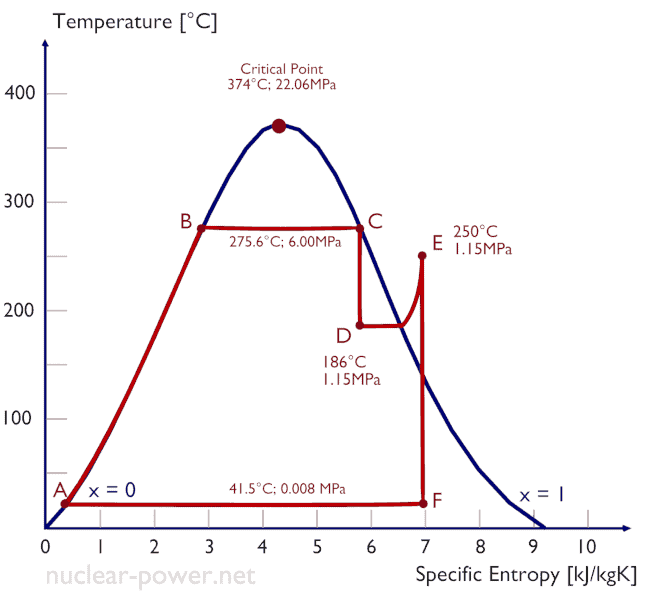
In these turbines the high-pressure stage receives steam (this steam is nearly saturated steam – x = 0.995 – point C at the figure; 6 MPa; 275.6°C) from a steam generator and exhaust it to moisture separator-reheater (point D). The steam must be reheated in order to avoid damages that could be caused to blades of steam turbine by low quality steam. The reheater heats the steam (point D) and then the steam is directed to the low-pressure stage of steam turbine, where expands (point E to F). The exhausted steam then condenses in the condenser and it is at a pressure well below atmospheric (absolute pressure of 0.008 MPa), and is in a partially condensed state (point F), typically of a quality near 90%.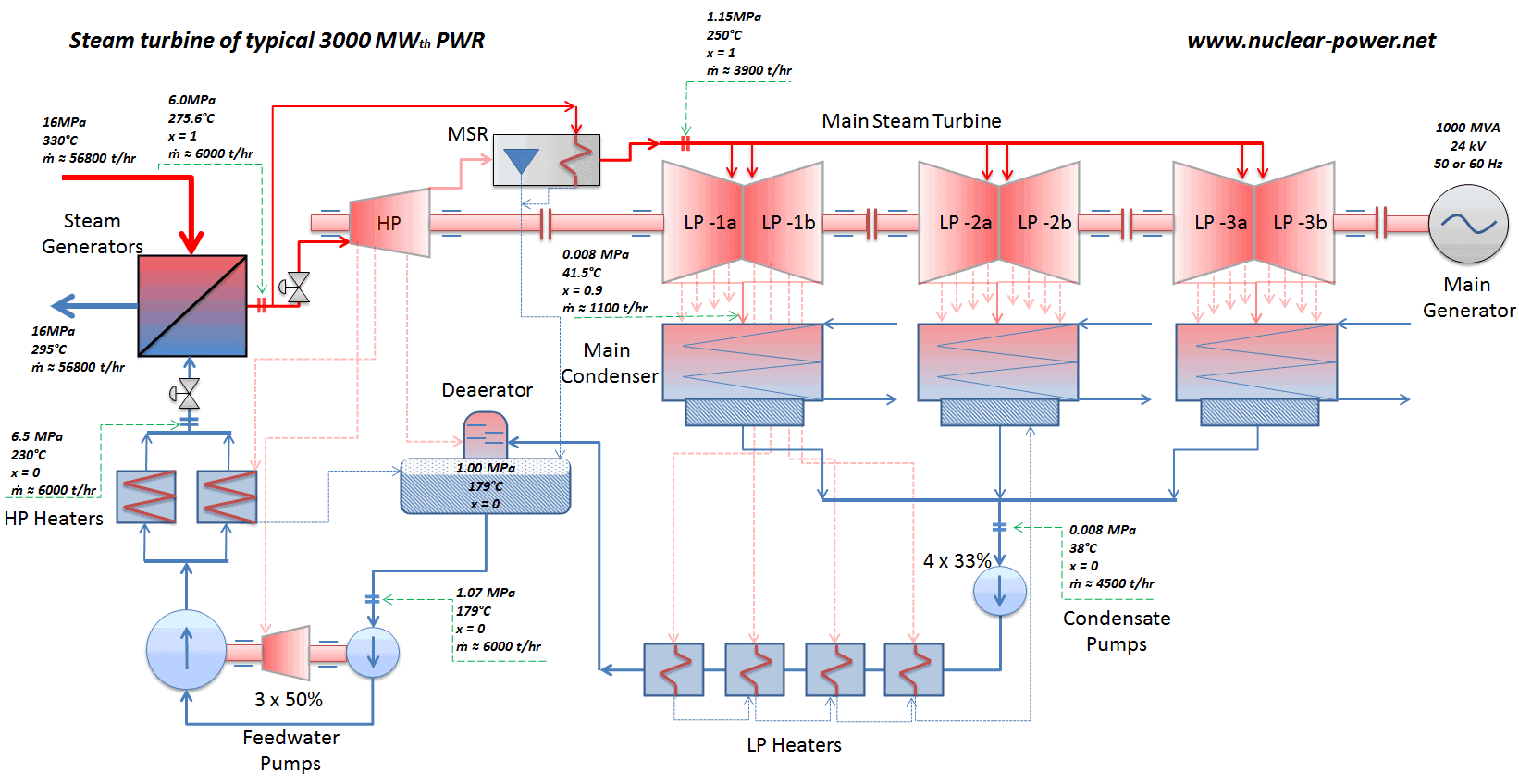
.
Today, the Rankine cycle is the fundamental operating cycle of all thermal power plants where an operating fluid is continuously evaporated and condensed. It is the one of most common thermodynamic cycles, because in most of the places in the world the turbine is steam-driven.
In contrast to Carnot cycle, the Rankine cycle does not execute isothermal processes, because these must be performed very slowly. In an ideal Rankine cycle, the system executing the cycle undergoes a series of four processes: two isentropic (reversible adiabatic) processes alternated with two isobaric processes.
Since Carnot’s principle states that no engine can be more efficient than a reversible engine (a Carnot heat engine) operating between the same high temperature and low temperature reservoirs, a steam turbine based on the Rankine cycle must have lower efficiency than the Carnot efficiency.
In modern nuclear power plants the overall thermal efficiency is about one-third (33%), so 3000 MWth of thermal power from the fission reaction is needed to generate 1000 MWe of electrical power. Higher efficiencies can be attained by increasing the temperature of the steam. But this requires an increase in pressures inside boilers or steam generators. However, metallurgical considerations place an upper limits on such pressures. In comparison to other energy sources the thermal efficiency of 33% is not much. But it must be noted that nuclear power plants are much more complex than fossil fuel power plants and it is much easier to burn fossil fuel ,than to generate energy from nuclear fuel.
A disadvantage is that water moderated reactors have to use high pressure primary circuit in order to keep water in liquid state and in order to achieve sufficient thermodynamic efficiency. Water and steam also reacts with metals commonly found in industries such as steel and copper that are oxidized faster by untreated water and steam. In almost all thermal power stations (coal, gas, nuclear), water is used as the working fluid (used in a closed loop between boiler, steam turbine and condenser), and the coolant (used to exchange the waste heat to a water body or carry it away by evaporation in a cooling tower).
Water and steam are a common medium because their properties are very well known. Their properties are tabulated in so called “Steam Tables”. In these tables the basic and key properties, such as pressure, temperature, enthalpy, density and specific heat, are tabulated along the vapor-liquid saturation curve as a function of both temperature and pressure. The properties are also tabulated for single-phase states (compressed water or superheated steam) on a grid of temperatures and pressures extending to 2000 ºC and 1000 MPa.
Further comprehensive authoritative data can be found at the NIST Webbook page on thermophysical properties of fluids.
See also: Steam Tables
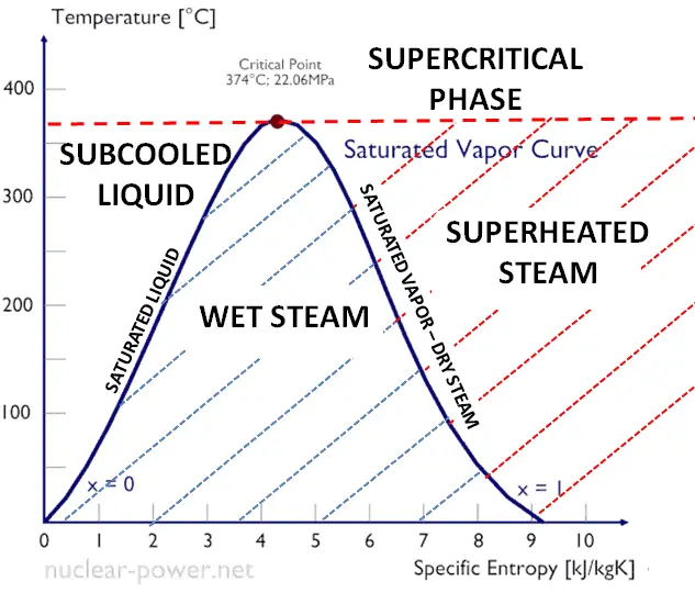
 In thermodynamics, the term saturation defines a condition in which a mixture of vapor and liquid can exist together at a given temperature and pressure. The temperature at which vaporization (boiling) starts to occur for a given pressure is called the saturation temperature or boiling point. The pressure at which vaporization (boiling) starts to occur for a given temperature is called the saturation pressure.
When the vapor quality is equal to 0, it is referred to as the saturated liquid state (single-phase). On the other hand, when the vapor quality is equal to 1, it is referred to as the saturated vapor state or dry steam (single-phase). Between these two states, we talk about vapor-liquid mixture or wet steam (two-phase mixture). At constant pressure, an addition of energy does not changes the temperature of the mixture, but the vapor quality and specific volume changes.
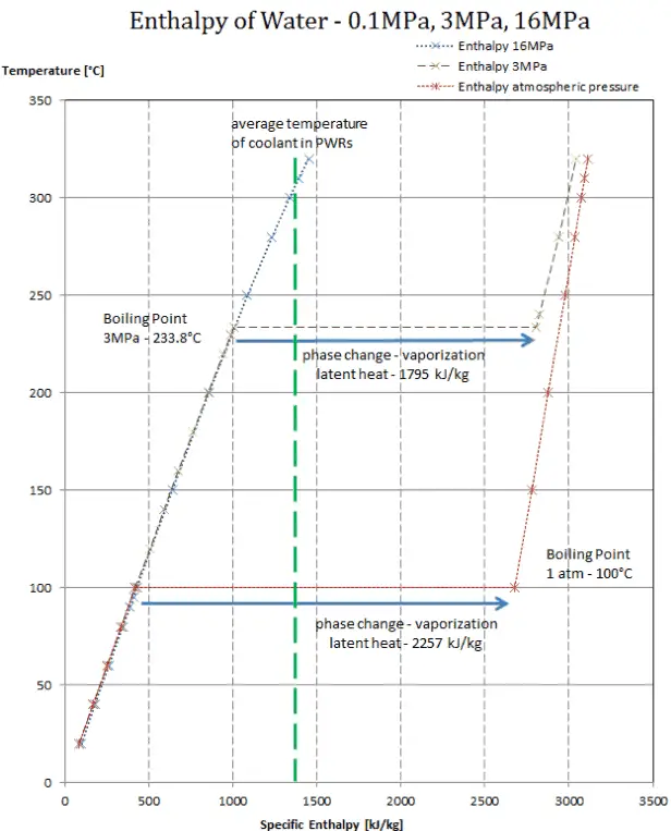
In general, when a material changes phase from solid to liquid, or from liquid to gas a certain amount of energy is involved in this change of phase. In case of liquid to gas phase change, this amount of energy is known as the enthalpy of vaporization, (symbol ∆Hvap; unit: J) also known as the (latent) heat of vaporization or heat of evaporation. Latent heat is the amount of heat added to or removed from a substance to produce a change in phase. This energy breaks down the intermolecular attractive forces, and also must provide the energy necessary to expand the gas (the pΔV work). When latent heat is added, no temperature change occurs. The enthalpy of vaporization is a function of the pressure at which that transformation takes place.
Latent heat of vaporization – water at 0.1 MPa (atmospheric pressure)
hlg = 2257 kJ/kg
Latent heat of vaporization – water at 3 MPa (pressure inside a steam generator)
hlg = 1795 kJ/kg
Latent heat of vaporization – water at 16 MPa (pressure inside a pressurizer)
hlg = 931 kJ/kg
The heat of vaporization diminishes with increasing pressure, while the boiling point increases. It vanishes completely at a certain point called the critical point. Above the critical point, the liquid and vapor phases are indistinguishable, and the substance is called a supercritical fluid.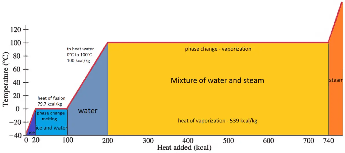
Rankine Cycle – Processes
In an ideal Rankine cycle, the system executing the cycle undergoes a series of four processes: two isentropic (reversible adiabatic) processes alternated with two isobaric processes:
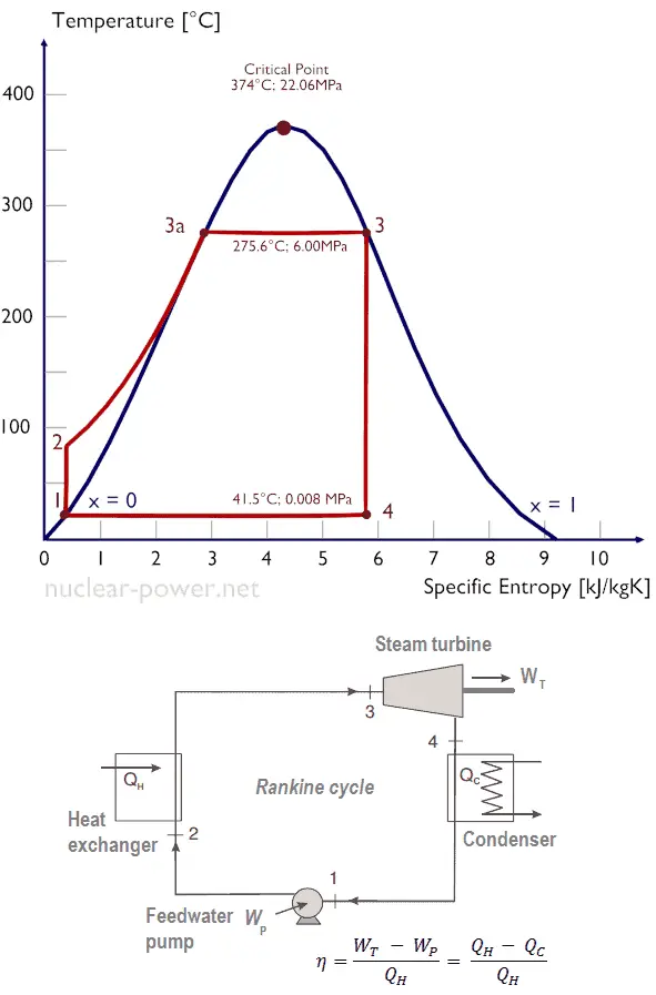
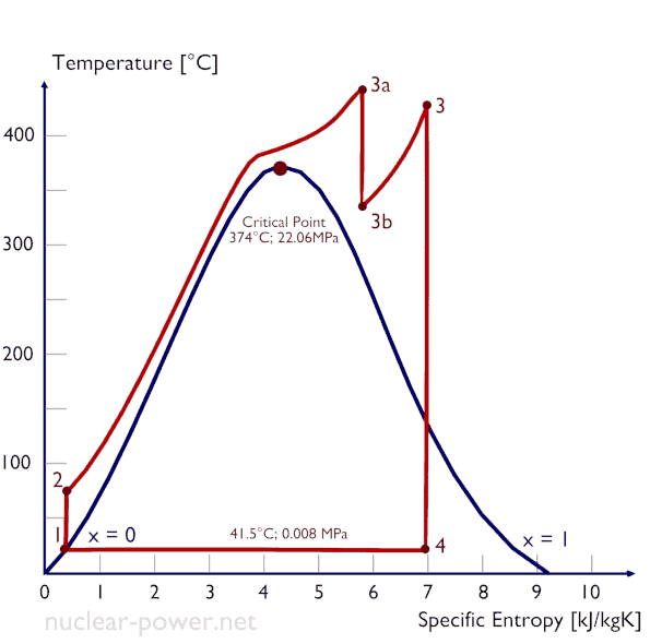
- Isobaric heat addition (in a heat exchanger – boiler) – In this phase (between state 2 and state 3) there is a constant-pressure heat transfer to the liquid condensate from an external source, since the chamber is open to flow in and out. The feedwater (secondary circuit) is heated from to the boiling point (2 → 3a) of that fluid and then evaporated in the boiler (3a → 3). The net heat added is given by Qadd = H3 – H2
- Isentropic expansion (expansion in a steam turbine) – Steam from the boiler expands adiabatically from state 3 to state 4 in a steam turbine to produce work and then is discharged to the condenser (partially condensed). The steam does work on the surroundings (blades of the turbine) and loses an amount of enthalpy equal to the work that leaves the system. The work done by turbine is given by WT = H4 – H3. Again the entropy remains unchanged.
- Isobaric heat rejection (in a heat exchanger) – In this phase the cycle completes by a constant-pressure process in which heat is rejected from the partially condensed steam. There is heat transfer from the vapor to cooling water flowing in a cooling circuit. The vapor condenses and the temperature of the cooling water increases. The net heat rejected is given by Qre = H4 – H1
During a Rankine cycle, work is done on the fluid by the pumps between states 1 and 2 (isentropic compression). Work is done by the fluid in the turbine between stages 3 and 4 (isentropic expansion). The difference between the work done by the fluid and the work done on the fluid is the net work produced by the cycle and it corresponds to the area enclosed by the cycle curve (in pV diagram). The working fluid in a Rankine cycle follows a closed loop and is reused constantly.
As can be seen, it is convenient to use enthalpy and the first law in terms of enthalpy in analysis of this thermodynamic cycle. This form of the law simplifies the description of energy transfer. At constant pressure, the enthalpy change equals the energy transferred from the environment through heating:
Isobaric process (Vdp = 0):
dH = dQ → Q = H2 – H1
At constant entropy, i.e. in isentropic process, the enthalpy change equals the flow process work done on or by the system:
Isentropic process (dQ = 0):
dH = Vdp → W = H2 – H1
See also: Why power engineers use enthalpy? Answer: dH = dQ + Vdp
Isentropic Process
An isentropic process is a thermodynamic process, in which the entropy of the fluid or gas remains constant. It means the isentropic process is a special case of an adiabatic process in which there is no transfer of heat or matter. It is a reversible adiabatic process. The assumption of no heat transfer is very important, since we can use the adiabatic approximation only in very rapid processes.
Isentropic Process and the First Law
For a closed system, we can write the first law of thermodynamics in terms of enthalpy:
dH = dQ + Vdp
or
dH = TdS + Vdp
Isentropic process (dQ = 0):
dH = Vdp → W = H2 – H1
Isobaric Process
An isobaric process is a thermodynamic process, in which the pressure of the system remains constant (p = const). The heat transfer into or out of the system does work, but also changes the internal energy of the system.
Since there are changes in internal energy (dU) and changes in system volume (∆V), engineers often use the enthalpy of the system, which is defined as:
H = U + pV
Isobaric Process and the First Law
The classical form of the first law of thermodynamics is the following equation:
dU = dQ – dW
In this equation dW is equal to dW = pdV and is known as the boundary work. In an isobaric process and the ideal gas, part of heat added to the system will be used to do work and part of heat added will increase the internal energy (increase the temperature). Therefore it is convenient to use the enthalpy instead of the internal energy.
Isobaric process (Vdp = 0):
dH = dQ → Q = H2– H1
At constant entropy, i.e. in isentropic process, the enthalpy change equals the flow process work done on or by the system.
Rankine Cycle – pV, Ts diagram
The Rankine cycle is often plotted on a pressure volume diagram (pV diagram) and on a temperature-entropy diagram (Ts diagram).
When plotted on a pressure volume diagram, the isobaric processes follow the isobaric lines for the gas (the horizontal lines), adiabatic processes move between these horizontal lines and the area bounded by the complete cycle path represents the total work that can be done during one cycle.
The temperature-entropy diagram (Ts diagram) in which the thermodynamic state is specified by a point on a graph with specific entropy (s) as the horizontal axis and absolute temperature (T) as the vertical axis. Ts diagrams are a useful and common tool, particularly because it helps to visualize the heat transfer during a process. For reversible (ideal) processes, the area under the T-s curve of a process is the heat transferred to the system during that process.
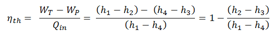
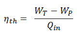
Thermal Efficiency of Rankine Cycle
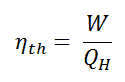
In general the thermal efficiency, ηth, of any heat engine is defined as the ratio of the work it does, W, to the heat input at the high temperature, QH.
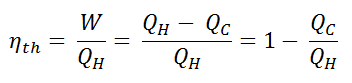
The thermal efficiency, ηth, represents the fraction of heat, QH, that is converted to work. Since energy is conserved according to the first law of thermodynamics and energy cannot be be converted to work completely, the heat input, QH, must equal the work done, W, plus the heat that must be dissipated as waste heat QC into the environment. Therefore we can rewrite the formula for thermal efficiency as:
This is very useful formula, but here we express the thermal efficiency using the first law in terms of enthalpy.
Typically most of nuclear power plants operates multi-stage condensing steam turbines. In these turbines the high-pressure stage receives steam (this steam is nearly saturated steam – x = 0.995 – point C at the figure; 6 MPa; 275.6°C) from a steam generator and exhaust it to moisture separator-reheater (point D). The steam must be reheated in order to avoid damages that could be caused to blades of steam turbine by low quality steam. The reheater heats the steam (point D) and then the steam is directed to the low-pressure stage of steam turbine, where expands (point E to F). The exhausted steam then condenses in the condenser and it is at a pressure well below atmospheric (absolute pressure of 0.008 MPa), and is in a partially condensed state (point F), typically of a quality near 90%.
In this case, steam generators, steam turbine, condensers and feedwater pumps constitute a heat engine, that is subject to the efficiency limitations imposed by the second law of thermodynamics. In ideal case (no friction, reversible processes, perfect design), this heat engine would have a Carnot efficiency of
= 1 – Tcold/Thot = 1 – 315/549 = 42.6%
where the temperature of the hot reservoir is 275.6°C (548.7K), the temperature of the cold reservoir is 41.5°C (314.7K). But the nuclear power plant is the real heat engine, in which thermodynamic processes are somehow irreversible. They are not done infinitely slowly. In real devices (such as turbines, pumps, and compressors) a mechanical friction and heat losses cause further efficiency losses.
To calculate the thermal efficiency of the simplest Rankine cycle (without reheating) engineers use the first law of thermodynamics in terms of enthalpy rather than in terms of internal energy.
The first law in terms of enthalpy is:
dH = dQ + Vdp
In this equation the term Vdp is a flow process work. This work, Vdp, is used for open flow systems like a turbine or a pump in which there is a “dp”, i.e. change in pressure. There are no changes in control volume. As can be seen, this form of the law simplifies the description of energy transfer. At constant pressure, the enthalpy change equals the energy transferred from the environment through heating:
Isobaric process (Vdp = 0):
dH = dQ → Q = H2 – H1
At constant entropy, i.e. in isentropic process, the enthalpy change equals the flow process work done on or by the system:
Isentropic process (dQ = 0):
dH = Vdp → W = H2 – H1
It is obvious, it will be very useful in analysis of both thermodynamic cycles used in power engineering, i.e. in Brayton cycle and Rankine cycle.
The enthalpy can be made into an intensive, or specific, variable by dividing by the mass. Engineers use the specific enthalpy in thermodynamic analysis more than the enthalpy itself. It is tabulated in the steam tables along with specific volume and specific internal energy. The thermal efficiency of such simple Rankine cycle and in terms of specific enthalpies would be:
It is very simple equation and for determination of the thermal efficiency you can use data from steam tables.
In modern nuclear power plants the overall thermal efficiency is about one-third (33%), so 3000 MWth of thermal power from the fission reaction is needed to generate 1000 MWe of electrical power. The reason lies in relatively low steam temperature (6 MPa; 275.6°C). Higher efficiencies can be attained by increasing the temperature of the steam. But this requires an increase in pressures inside boilers or steam generators. However, metallurgical considerations place an upper limits on such pressures. In comparison to other energy sources the thermal efficiency of 33% is not much. But it must be noted that nuclear power plants are much more complex than fossil fuel power plants and it is much easier to burn fossil fuel ,than to generate energy from nuclear fuel. Sub-critical fossil fuel power plants, that are operated under critical pressure (i.e. lower than 22.1 MPa), can achieve 36–40% efficiency.
Causes of Inefficiency
As was discussed, an efficiency can range between 0 and 1. Each heat engine is somehow inefficient. This inefficiency can be attributed to three causes.
- Irreversibility of Processes. There is an overall theoretical upper limit to the efficiency of conversion of heat to work in any heat engine. This upper limit is called the Carnot efficiency. According to the Carnot principle, no engine can be more efficient than a reversible engine (a Carnot heat engine) operating between the same high temperature and low temperature reservoirs. For example, when the hot reservoir have Thot of 400°C (673K) and Tcold of about 20°C (293K), the maximum (ideal) efficiency will be: = 1 – Tcold/Thot = 1 – 293/673 = 56%. But all real thermodynamic processes are somehow irreversible. They are not done infinitely slowly. Therefore, heat engines must have lower efficiencies than limits on their efficiency due to the inherent irreversibility of the heat engine cycle they use.
- Presence of Friction and Heat Losses. In real thermodynamic systems or in real heat engines, a part of the overall cycle inefficiency is due to the losses by the individual components. In real devices (such as turbines, pumps, and compressors) a mechanical friction, heat losses and losses in the combustion process cause further efficiency losses.
- Design Inefficiency. Finally, last and also important source of inefficiencies is from the compromises made by engineers when designing a heat engine (e.g. power plant). They must consider cost and other factors in the design and operation of the cycle. As an example consider a design of the condenser in the thermal power plants. Ideally the steam exhausted into the condenser would have no subcooling. But real condensers are designed to subcool the liquid by a few degrees of Celsius in order to avoid the suction cavitation in the condensate pumps. But, this subcooling increases the inefficiency of the cycle, because more energy is needed to reheat the water.
Thermal Efficiency Improvement – Rankine Cycle
There are several methods, how can be the thermal efficiency of the Rankine cycle improved. Assuming that the maximum temperature is limited by the pressure inside the reactor pressure vessel, these methods are:
Condenser Pressure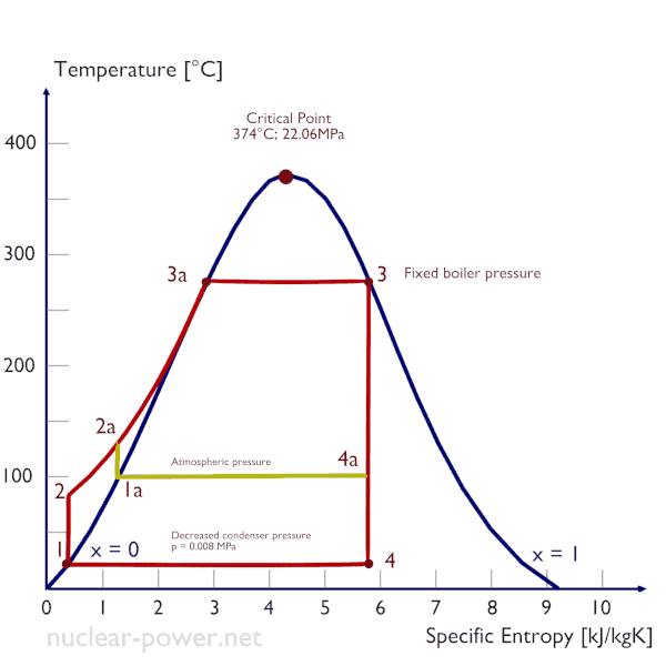
The case of the decrease in the average temperature at which energy is rejected, requires a decrease in the pressure inside condenser (i.e. the decrease in the saturation temperature). The lowest feasible condenser pressure is the saturation pressure corresponding to the ambient temperature (i.e. absolute pressure of 0.008 MPa, which corresponds to 41.5°C). The goal of maintaining the lowest practical turbine exhaust pressure is a primary reason for including the condenser in a thermal power plant. The condenser provides a vacuum that maximizes the energy extracted from the steam, resulting in a significant increase in net work and thermal efficiency. But also this parameter (condenser pressure) has its engineering limits:
- Decreasing the turbine exhaust pressure decreases the vapor quality (or dryness fraction). At some point the expansion must be ended to avoid damages that could be caused to blades of steam turbine by low quality steam.
- Decreasing the turbine exhaust pressure significantly increases the specific volume of exhausted steam, which requires huge blades in last rows of low-pressure stage of the steam turbine.
In a typical wet steam turbines, the exhausted steam condenses in the condenser and it is at a pressure well below atmospheric (absolute pressure of 0.008 MPa, which corresponds to 41.5°C). This steam is in a partially condensed state (point F), typically of a quality near 90%. Note that, there is always a temperature difference between (around ΔT = 14°C) the condenser temperature and the ambient temperature, which originates from finite size and efficiency of condensers.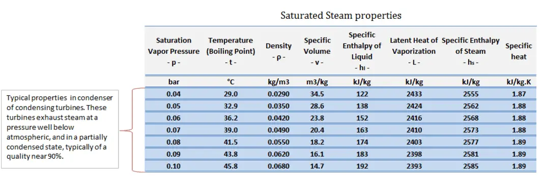
Boiler Pressure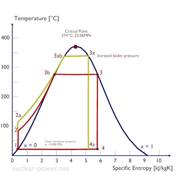
The case of the increase in the average temperature at which energy is added by heat transfer, requires either a superheating of steam produced or an increase in the pressure in the boiler (steam generator). Superheating is not typical for nuclear power plants.
Typically most of nuclear power plants operates multi-stage condensing steam turbines. In these turbines the high-pressure stage receives steam (this steam is nearly saturated steam – x = 0.995 – point C at the figure; 6 MPa; 275.6°C). Since neither the steam generator is 100% efficient, there is always a temperature difference between the saturation temperature (secondary side) and the temperature of the primary coolant.
In a typical pressurized water reactor, the hot primary coolant (water 330°C; 626°F) is pumped into the steam generator through primary inlet. This requires maintaining of very high pressures to keep the water in the liquid state. In order to prevent boiling of the primary coolant and to provide a subcooling margin (the difference between the pressurizer temperature and the highest temperature in the reactor core), pressures around 16 MPa are typical for PWRs. The reactor pressure vessel is the key component, which limits the thermal efficiency of each nuclear power plant, since the reactor vessel must withstand high pressures.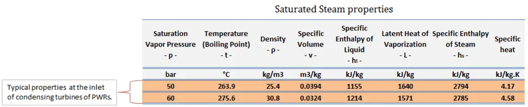
 As for the Carnot cycle, the thermal efficiency tends to increase as the average temperature at which energy is added by heat transfer increases. This is the common feature of all thermodynamic cycles.
One of possible ways is to superheat or reheat the working steam. Both processes are very similar in its manner:
- Superheater – increases the steam temperature above the saturation temperature
- Reheater – removes the moisture and increases steam temperature after a partial expansion.
The process of superheating is the only way to increase the peak temperature of the Rankine cycle (and to increase efficiency) without increasing the boiler pressure. This requires the addition of another type of heat exchanger called a superheater, which produces the superheated steam.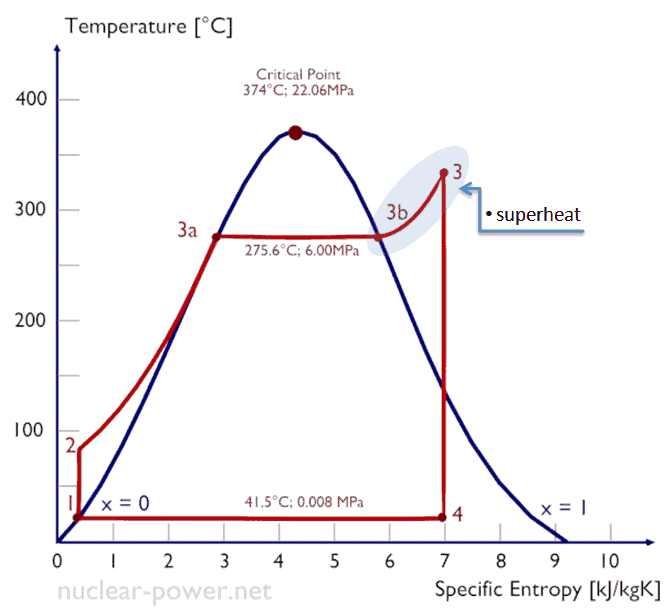
Superheated vapor or superheated steam is a vapor at a temperature higher than its boiling point at the absolute pressure where the temperature is measured.
Reheat allows to deliver more of the heat at a temperature close to the peak of the cycle. This requires the addition of another type of heat exchanger called a reheater. The use of the reheater involves splitting the turbine, i.e. use of a multistage turbine with a reheater. It was observed that more than two stages of reheating are unnecessary, since the next stage increases the cycle efficiency only half as much as the preceding stage.
High pressure and low pressure stages of the turbine are usually on the same shaft to drive a common generator, but they have separate cases. With a reheater, the flow is extracted after a partial expansion (point D), run back through the heat exchanger to heat it back up to the peak temperature (point E), and then passed to the low-pressure turbine. The expansion is then completed in the low-pressure turbine from point E to point F.
In the superheater, further heating at fixed pressure results in increases in both temperature and specific volume. The process of superheating of water vapor in the T-s diagram is provided in the figure between state E and saturation vapor curve. As can be seen also wet steam turbines (e.g. used in nuclear power plants) use superheated steam especially at the inlet of low-pressure stages. Typically most of nuclear power plants operates multi-stage condensing wet steam turbines (the high pressure stage runs on saturated steam). In these turbines the high-pressure stage receives steam (this steam is nearly saturated steam – x = 0.995 – point C at the figure) from a steam generator and exhaust it to moisture separator-reheater (point D). The steam must be reheated or superheated in order to avoid damages that could be caused to blades of steam turbine by low quality steam. High content of water droplets can cause the rapid impingement and erosion of the blades which occurs when condensed water is blasted onto the blades. To prevent this, condensate drains are installed in the steam piping leading to the turbine. The reheater heats the steam (point D) and then the steam is directed to the low-pressure stage of steam turbine, where expands (point E to F). The exhausted steam is at a pressure well below atmospheric, and, as can be seen from the picture, the steam is in a partially condensed state (point F), typically of a quality near 90%, but it is much higher vapor quality, than that it would be without reheat. Accordingly, superheating also tends to alleviate the problem of low vapor quality at the turbine exhaust.
Since the temperature of the primary coolant is limited by the pressure inside the reactor, superheaters (except a moisture separator reheater) are not used in nuclear power plants and they operate usually a single wet steam turbine.
As was discussed the thermal efficiency can be improved “simply” by an increase in the temperature of the steam entering the turbine. But this temperature is restricted by metallurgical limitations imposed by the materials and design of the reactor pressure vessel and primary piping. The reactor vessel and the primary piping must withstand high pressures and great stresses at elevated temperatures. But currently, improved materials and methods of fabrication have permitted significant increases in the maximum pressures, with corresponding increases in thermal efficiency. The thermal power plants are currently designed to operate on the supercritical Rankine cycle (i.e. with steam pressures exceeding the critical pressure of water 22.1 MPa, and turbine inlet temperatures exceeding 600 °C). Supercritical fossil fuel power plants, that are operated at supercritical pressure, have efficiencies around 43%. Most efficient and also very complex coal-fired power plants that are operated at “ultra critical” pressures (i.e. around 30 MPa) and use multiple stage reheat reach about 48% efficiency.
Supercritical Water Reactor – SCWR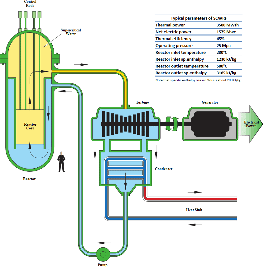
Supercritical Rankine cycle is also the thermodynamic cycle of supercritical water reactors. The supercritical water reactor (SCWR) is a concept of Generation IV reactor, that is operated at supercritical pressure (i.e. greater than 22.1 MPa). The term supercritical in this context refers to the thermodynamic critical point of water (TCR = 374 °C; pCR = 22.1 MPa), and must not be confused with the criticality of the reactor core, that describes changes in the neutron population in the reactor core.
For SCWRs a once through steam cycle has been envisaged, omitting any coolant recirculation inside the reactor. It is similar as in boiling water reactors, steam will be supplied directly to the steam turbine and the feed water from the steam cycle will be supplied back to the core.
As well as the supercritical water reactor may use light water or heavy water as neutron moderator. As can be seen, there are many SCWR designs, but all SCWRs have a key feature, that is the use of water beyond the thermodynamic critical point as primary coolant. Since this feature allows to increase the peak temperature, the supercritical water reactors are considered a promising advancement for nuclear power plants because of its high thermal efficiency (~45 % vs. ~33 % for current LWRs).
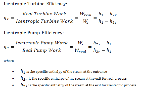
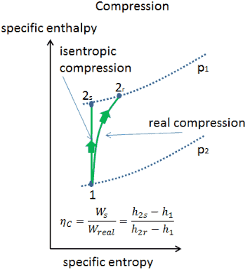
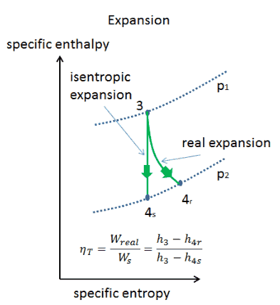
Isentropic Efficiency – Turbine, Pump
In previous chapters we assumed that the steam expansion is isentropic and therefore we used T4,is as the outlet temperature of the gas. These assumptions are only applicable with ideal cycles.
Most steady-flow devices (turbines, compressors, nozzles) operate under adiabatic conditions, but they are not truly isentropic but are rather idealized as isentropic for calculation purposes. We define parameters ηT, ηP, ηN, as a ratio of real work done by device to work by device when operated under isentropic conditions (in case of turbine). This ratio is known as the Isentropic Turbine/Pump/Nozzle Efficiency. These parameters describe how efficiently a turbine, compressor or nozzle approximates a corresponding isentropic device. This parameter reduces the overall efficiency and work output. For turbines, the value of ηT is typically 0.7 to 0.9 (70–90%).
See also: Isentropic Process
Steam Turbine – Problem with Solution
Calculate:
- the vapor quality of the outlet steam
- the enthalpy difference between these two states (3 → 4), which corresponds to the work done by the steam, WT.
- the enthalpy difference between these two states (1 → 2), which corresponds to the work done by pumps, WP.
- the enthalpy difference between these two states (2 → 3), which corresponds to the net heat added in the steam generator
- the thermodynamic efficiency of this cycle and compare this value with the Carnot’s efficiency
1)
Since we do not know the exact vapor quality of the outlet steam, we have to determine this parameter. State 4 is fixed by the pressure p4 = 0.008 MPa and the fact that the specific entropy is constant for the isentropic expansion (s3 = s4 = 5.89 kJ/kgK for 6 MPa). The specific entropy of saturated liquid water (x=0) and dry steam (x=1) can be picked from steam tables. In case of wet steam, the actual entropy can be calculated with the vapor quality, x, and the specific entropies of saturated liquid water and dry steam:
s4 = sv x + (1 – x ) sl
where
s4 = entropy of wet steam (J/kg K) = 5.89 kJ/kgK
sv = entropy of “dry” steam (J/kg K) = 8.227 kJ/kgK (for 0.008 MPa)
sl = entropy of saturated liquid water (J/kg K) = 0.592 kJ/kgK (for 0.008 MPa)
From this equation the vapor quality is:
x4 = (s4 – sl) / (sv – sl) = (5.89 – 0.592) / (8.227 – 0.592) = 0.694 = 69.4%
2)
The enthalpy for the state 3 can be picked directly from steam tables, whereas the enthalpy for the state 4 must be calculated using vapor quality:
h3, v = 2785 kJ/kg
h4, wet = h4,v x + (1 – x ) h4,l = 2576 . 0.694 + (1 – 0.694) . 174 = 1787 + 53.2 = 1840 kJ/kg
Then the work done by the steam, WT, is
WT = Δh = 945 kJ/kg
3)
Enthalpy for state 1 can be picked directly from steam tables:
h1, l = 174 kJ/kg
State 2 is fixed by the pressure p2 = 6.0 MPa and the fact that the specific entropy is constant for the isentropic compression (s1 = s2 = 0.592 kJ/kgK for 0.008 MPa). For this entropy s2 = 0.592 kJ/kgK and p2 = 6.0 MPa we find h2, subcooled in steam tables for compressed water (using interpolation between two states).
h2, subcooled = 179.7 kJ/kg
Then the work done by the pumps, WP, is
WP = Δh = 5.7 kJ/kg
4)
The enthalpy difference between (2 → 3), which corresponds to the net heat added in the steam generator, is simply:
Qadd = h3, v – h2, subcooled = 2785 – 179.7 = 2605.3 kJ/kg
Note that, there is no heat regeneration in this cycle. On the other hand most of the heat added is for the enthalpy of vaporization (i.e. for the phase change).
5)
In this case, steam generators, steam turbine, condensers and feedwater pumps constitute a heat engine, that is subject to the efficiency limitations imposed by the second law of thermodynamics. In the ideal case (no friction, reversible processes, perfect design), this heat engine would have a Carnot efficiency of
ηCarnot = 1 – Tcold/Thot = 1 – 315/549 = 42.6%
where the temperature of the hot reservoir is 275.6°C (548.7 K), the temperature of the cold reservoir is 41.5°C (314.7K).
The thermodynamic efficiency of this cycle can be calculated by the following formula:
thus
ηth = (945 – 5.7) / 2605.3 = 0.361 = 36.1%
We hope, this article, Theory of Steam Turbines – Thermodynamics, helps you. If so, give us a like in the sidebar. Main purpose of this website is to help the public to learn some interesting and important information about thermal engineering.