Flow Patterns – Two-phase Flow
One of the most challenging aspects of dealing with two-phase flow or multi-phase flow is the fact that it can take many different forms. Spatial distributions and velocities of the liquid and vapor phases in the flow channel is very important aspect in many engineering branches. Pressure drops and also heat transfer coefficients strongly depends on the local flow structure and thus it is of importance in engineering of nuclear reactors. The observed flow structures are defined as two-phase flow patterns and these have particular identifying characteristics. These different flow patterns have been categorized according to the direction of flow relative to gravitational acceleration.
- Flow patterns in vertical tubes
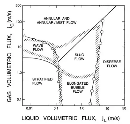
- Flow patterns in horizontal tubes
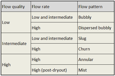
The main flow regimes in vertical tubes are shown in the table. It must be noted values of flow quality and flow rate are dependent on the fluid and pressure. In horizontal tubes, there can also be stratified flow (especially at low flow rates), at which the two phases separate under the effect of gravity.
For a constant liquid flow rate, the vapor/gas phase tends to be distributed as small bubbles at low vapor flow rates. Increasing void fraction causes agglomeration of bubbles into larger plugs and slugs. Further agglomeration of slugs, cause by further increasing void fraction causes separation of the phases into annular patterns wherein liquid concentrates at the channel wall and vapor flows in the central core of the vertical channel.
For horizontal channel, gravitational force tends to drain the liquid annulus toward the bottom of the channel, resulting in stratified flow. The gravitational force acting on the liquid phase can be overcome by kinetic forces at high flow rates, causing stratified flows to revert to annular flows. At very high flow rates, the annular film is thinned by the shear of the vapor core and all the liquid is entrained as droplets in the vapor phase. This flow regime is usually known as the mist flow.
See also: Engineering Data Book III, Thome, J.R., Wolverine Tube Inc, 2004.
Flow Patterns – Vertical Tubes
[/su_accordion]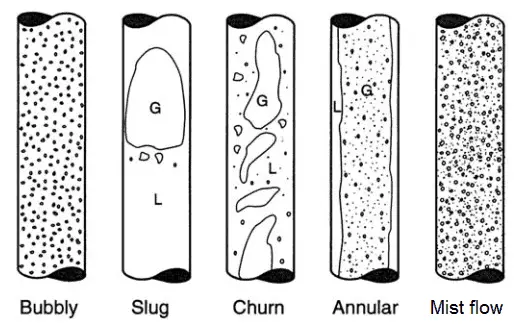
Flow Patterns – Horizontal Tubes
[/su_accordion]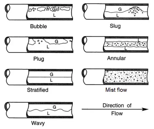
Flow patterns during evaporation
The previous section describes various flow patterns and shortly describes their behavior. These flow patterns were considered to be at constant void fraction and at constant superficial velocities. But there are many industrial applications that have to consider a variable void fraction and variable superficial velocities. In nuclear industry, we have to deal with flow patterns during evaporation (i.e. during changes in the void fraction).
Detailed knowledge of phase changes and the behavior of the flow during the phase change is one of the most important considerations in the design of a nuclear reactor, especially in following applications:
- A boiling water reactor is cooled and moderated by water like a PWR, but at a lower pressure (7MPa), which allows the water to boil inside the pressure vessel producing the steam that runs the turbines. Evaporation therefore occurs directly in fuel channels. Therefore BWRs are the best example for this area, because evaporation of coolant occurs at normal operation and it is very desired phenomenon.
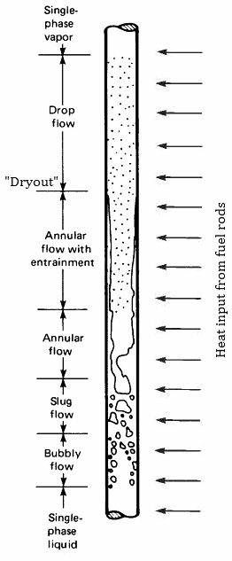
- In BWRs there is a phenomenon, that is of the highest importance in reactor safety. This phenomenon is known as the “dryout” and it is directly associated with changes in flow pattern during evaporation. At normal the fuel surface is effectively cooled by boiling coolant. However when the heat flux exceeds a critical value (CHF – critical heat flux) the flow pattern may reach the dryout conditions (thin film of liquid disappears). The heat transfer from the fuel surface into the coolant is deteriorated, with the result of a drastically increased fuel surface temperature.
- PWR – Pressurized Water Reactors
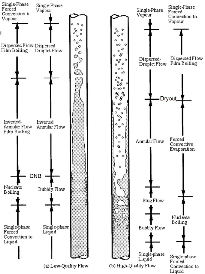
- In PWRs at normal operation the flow is considered to be single-phase. But a great deal of study has been performed on the nature of two-phase flow in case of transients and accidents (such as the loss-of-coolant accident – LOCA or trip of RCPs), which are of importance in reactor safety and in must be proved and declared in the Safety Analysis Report (SAR). In case of PWRs, the problematic phenomenon is not the dryout. In case of PWRs, the critical flow is inverted annular flow. This flow occurs when a fuel rod cladding surface is overheated, which causes the formation of a local vapor layer, causing a dramatic reduction in heat transfer capability. This phenomenon is known as departure from nucleate boiling – DNB. The difference in flow regime between post-dryout flow and post-DNB flow is depicted in the figure.
- In PWRs, evaporation occurs also in steam generators. Steam generators are heat exchangers used to convert feedwater into steam from heat produced in a nuclear reactor core. The steam produced drives the turbine.
Further increase in liquid temperature causes, that the liquid bulk reaches its saturation temperature and the convective boiling process passes through the bubbly flow into the slug flow. Increasing void fraction causes that the structure of the flow becomes unstable. The boiling process passes through the slug and churn flow into the annular flow regime with its characteristic annular film of the liquid. At given combinations of flow rate through a channel, pressure, flow quality, and linear heat rate, the wall liquid film may exhaust and the wall may be dried out. At the dryout point the wall temperature significantly rises in order to dissipate the applied heat flux. The post-dryout flow (mist or drop flow) in the heated channel is undesirable, because the presence of such flow regime is accompanied with significantly higher wall temperatures and high fluctuation of wall temperatures.
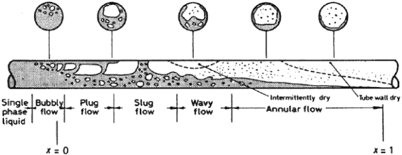
At the inlet, the liquid enters subcooled (at the lower temperature than saturation). In this region the flow is single-phase. As the liquid heats up, the wall temperature correspondingly rises. As the wall temperature exceeds the saturation temperature (e.g. 285°C at 6.8 MPa), subcooled boiling begins. The convective boiling process passes through bubbly, plug regimes and flow can be either stratified or unstratified (depending on the flow velocity). As can be seen, channel dryout occurs at the top of the tube where the film thickness is thinner due to gravitational force. Dryout then progresses around the perimeter from top to bottom along the channel.
We hope, this article, Flow Pattern – Two-phase Flow, helps you. If so, give us a like in the sidebar. Main purpose of this website is to help the public to learn some interesting and important information about thermal engineering.