Cooling Towers
 The cooling towers are devices that reject waste heat to the atmosphere through the cooling of a water stream to a lower temperature. Cooling towers are built on places where is scarcity of the water. By using cooling towers the cooling water requirement is reduced and only makeup water is to be supplied. The cooling towers significantly reduce the cooling water demand but it is achieved at the expense of large capital costs.
With respect to the heat transfer mechanism employed, the main types are:
Dry cooling towers operate by heat transfer through a surface that separates the working fluid from ambient air, such as in a tube to air heat exchanger, utilizing convective heat transfer. They do not use evaporation, hence the consumption of makeup water is minimal.
Wet cooling towers (or open circuit cooling towers) operate on the principle of evaporative cooling. Evaporative cooling is the addition of water vapor into air, which causes a lowering of the temperature of the air and the water too. The energy needed to evaporate the water is taken from the remaining mass of water, thus reducing its temperature. The cooling water from the plant is pumped to a height of about 10 m and distributed over the cooling tower fill, cascading down the fill to the well at the bottom. Inside the wet cooling tower, fills are added to increase contact surface as well as contact time between air and water, to provide better heat transfer.
Nearly all nuclear power plants, which use cooling towers, use the wet cooling towers based on the principle of evaporative cooling. Some water about 1% goes into air in the form of water vapor by absorbing its latent heat of vaporization from the remaining water and thus causes the reduction in the water temperature as ambient air is drawn past a flow of water. The remaining water (cooled) is collected in a sump at the bottom of the tower and returned back to the condenser.
The types of cooling towers on the basis of the draught (method of air circulation) are:
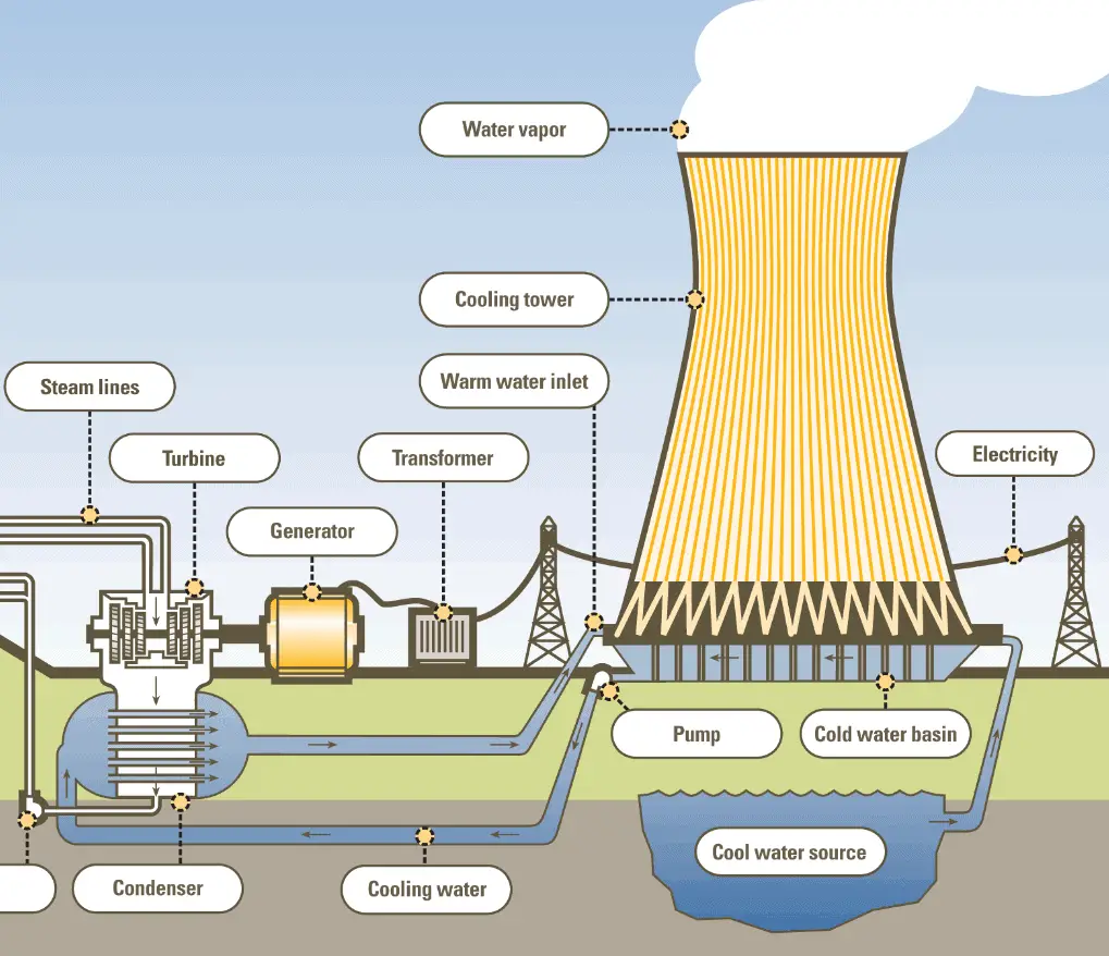
- Natural draught cooling towers. Natural draught cooling towers utilize buoyancy via a tall hyperboloid chimney. Hyperboloid cooling towers are typical for natural draught cooling towers because of their structural strength and because of the fact that the hyperboloid shape also aids in accelerating the upward convective air flow, improving cooling efficiency. In this cooling tower the hot cooling water (e.g. 25°C) from the condenser is pumped to a height of about 10 m, enters the tower and then sprayed over the trays. Water droplets fall down and meets the colder air entering from the bottom of the tower which is open to the atmosphere. Hot water (e.g. 25°C) gives up its heat to the air and gets cooled (e.g. 22°C). Warm, moist air naturally rises due to the density differential compared to the dry, cooler outside air. Warm moist air is less dense than drier air at the same pressure. This moist air buoyancy produces an upwards current of air through the hyperboloid tower. The cooled water falls down in the form of rain and gets collected in the pond at the bottom of the tower.
- Mechanical draught cooling towers. In general, in the mechanical draught cooling towers the air is circulated with the use of a mechanical device like a fan or a blower.
- Forced draught cooling towers. Forced draught cooling towers uses the fan, which is installed at the bottom of the tower. This produces high entering and low exiting air velocities, therefore this towers are much more susceptible to recirculation.
- Induced draught cooling towers. Induced draught cooling towers uses the fan, which is installed at the top of the tower. This produces low entering and high exiting air velocities, reducing the possibility of recirculation in which discharged air flows back into the air intake.
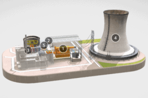
Special link: 3D model of NPP – sketchfab.com
Cooling System – Circulating Water System
The cooling system or the circulating water system provides a continuous supply of cooling water to the main condenser to remove the heat rejected by the turbine and auxiliary systems (e.g. the turbine bypass system). In this process the cooling water becomes hot. This energy is rejected to the atmosphere via cooling towers or directly to the seawater or to a river. Note that, not all nuclear power plants have cooling towers and conversely, the same kind of cooling towers are often used at large coal-fired power plants as well.
Cooling System in Wet Steam Turbines
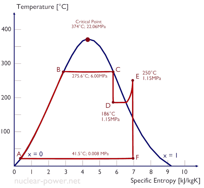
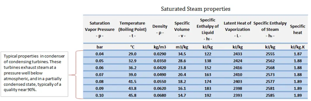
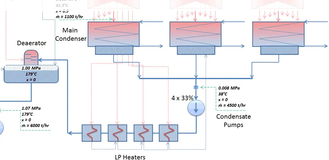
In a typical condensing steam turbine, the exhausted steam condenses in the condenser and it is at a pressure well below atmospheric (absolute pressure of 0.008 MPa, which corresponds to 41.5°C). This steam is in a partially condensed state (point F), typically of a quality near 90%.
The pressure inside condenser (thus the enthalpy of outlet steam) is given by the ambient air temperature (i.e. temperature of water in the cooling system). and other parameters:
- air temperature, pressure and humidity in case of cooling into the atmosphere
- water temperature and the flow rate in case of cooling into a river or sea
An increase in the ambient temperature may cause a proportional increase in pressure of exhausted steam (ΔT = 14°C is usually a constant) hence the thermal efficiency of the power conversion system may decrease. In other words, the electrical output of a power plant may vary with ambient conditions, while the thermal power remains constant.
It must be noted there is also lower limit for the steam outlet temperature, thus for the cooling system. Below 0.008 MPa and 41.5 °C the specific volume of exhausted steam significantly increases which requires huge blades in last rows of low-pressure stage of the steam turbine. Moreover, with a decrease in the turbine exhaust pressure the vapor quality decreases (or dryness fraction). At some point the expansion must be ended to avoid damages that could be caused to blades of steam turbine by low quality steam.
In modern nuclear power plants the overall thermal efficiency is about one-third (33%), so 3000 MWth of thermal power from the fission reaction is needed to generate 1000 MWe of electrical power. Therefore about 2000MWth of unusable energy must be rejected in order to fulfill the second law of thermodynamics.
To maintain the parameters inside the condenser (0.008 MPa and 41.5 °C), the cooling water must be sufficiently cold and there cannot be large temperature difference between the outlet and inlet water temperauter, hence the flowrate through the cooling system must be very high. The flowrate through the cooling system (with wet cooling towers) may be up to 100 000 m3/h (27.7 m3/s). The condenser inlet water may have about 22°C (strongly depending on ambient conditions), while the condenser outlet may have about 25°C.
The sea water cooling systems operate at higher flowrates, for example, 130 000 m3/h. In general, the energy can be rejected to the atmosphere via cooling towers or directly to the seawater or to a river.
We hope, this article, Cooling Tower – Dry, Wet – Natural draught, helps you. If so, give us a like in the sidebar. Main purpose of this website is to help the public to learn some interesting and important information about thermal engineering.