Feedwater Heating System – Heat Regeneration
In general, the feedwater heating system consists of:
- low-pressure feedwater heaters
- deaerator
- high-pressure feedwater heaters
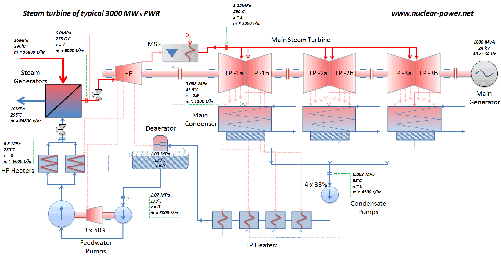
Low-pressure feedwater heaters
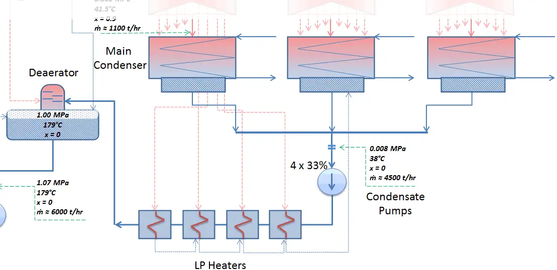 The condensate from condensate pumps then passes through several stages of low pressure feedwater heaters, in which the temperature of the condensate is increased by heat transfer from steam extracted from the low pressure turbines. There are usually three or four stages of low pressure feedwater heaters connected in the cascade. The condensate exits the low pressure feedwater heaters at approximately p = 1 MPa, t = 150°C and enters the deaerator. The main condensate system also contains a mechanical condensate purification system for removing impurities. The feedwater heaters are self-regulating. It means that the greater the flow of feedwater the greater the rate of heat absorption from the steam and the greater the flow of extraction steam.
There are non-return valves in the extraction steam lines between the feedwater heaters and turbine. These non-return valves prevent the reverse steam or water flow in case of turbine trip, which causes rapid decrease in the pressure inside the turbine. Any water entering the turbine in this way could cause severe damage to the turbine blading.
Deaerator
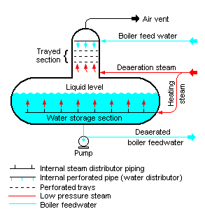
In the deaerator, the condensate is heated to saturated conditions usually by the steam extracted from the steam turbine. The extraction steam are mixed in the deaerator by a system of spray nozzles and cascading trays between which the steam percolates. Any dissolved gases in the condensate are released in this process and removed from the deaerator by venting to the atmosphere or to the main condenser. Directly below the deaerator is the feedwater storage tank, in which a large quantity of feedwater is stored at near saturation conditions. In the turbine trip event, this feedwater can be supplied to steam generators to maintain the required water inventory during transient. The deaerator and the storage tank is usually located at a high elevation in the turbine hall to ensure an adequate net positive suction head (NPSH) at the inlet to the feedwater pumps. NPSH is used to measure how close a fluid is to saturated conditions. Lowering the pressure at the suction side can induce cavitation. This arrangement minimizes the risk of cavitation in the pump.
High-pressure feedwater heaters
 The water discharge from the feedwater pumps flows through the high pressure feedwater heaters, enters the containment and then flows into the steam generators.
The high pressure feedwater heaters are heated by extraction steam from the high pressure turbine, HP Turbine. Drains from the high-pressure feedwater heaters are usually routed to the deaerator.
The feedwater (water 230°C; 446°F; 6,5MPa) is pumped into the steam generator through the feedwater inlet.
We hope, this article, Feedwater Heating System – Heat Regeneration, helps you. If so, give us a like in the sidebar. Main purpose of this website is to help the public to learn some interesting and important information about thermal engineering.