From Boiler to Main Steam Lines – Evaporation
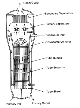
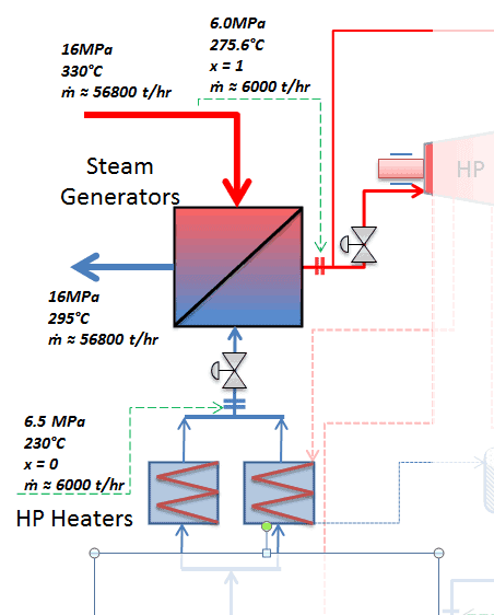
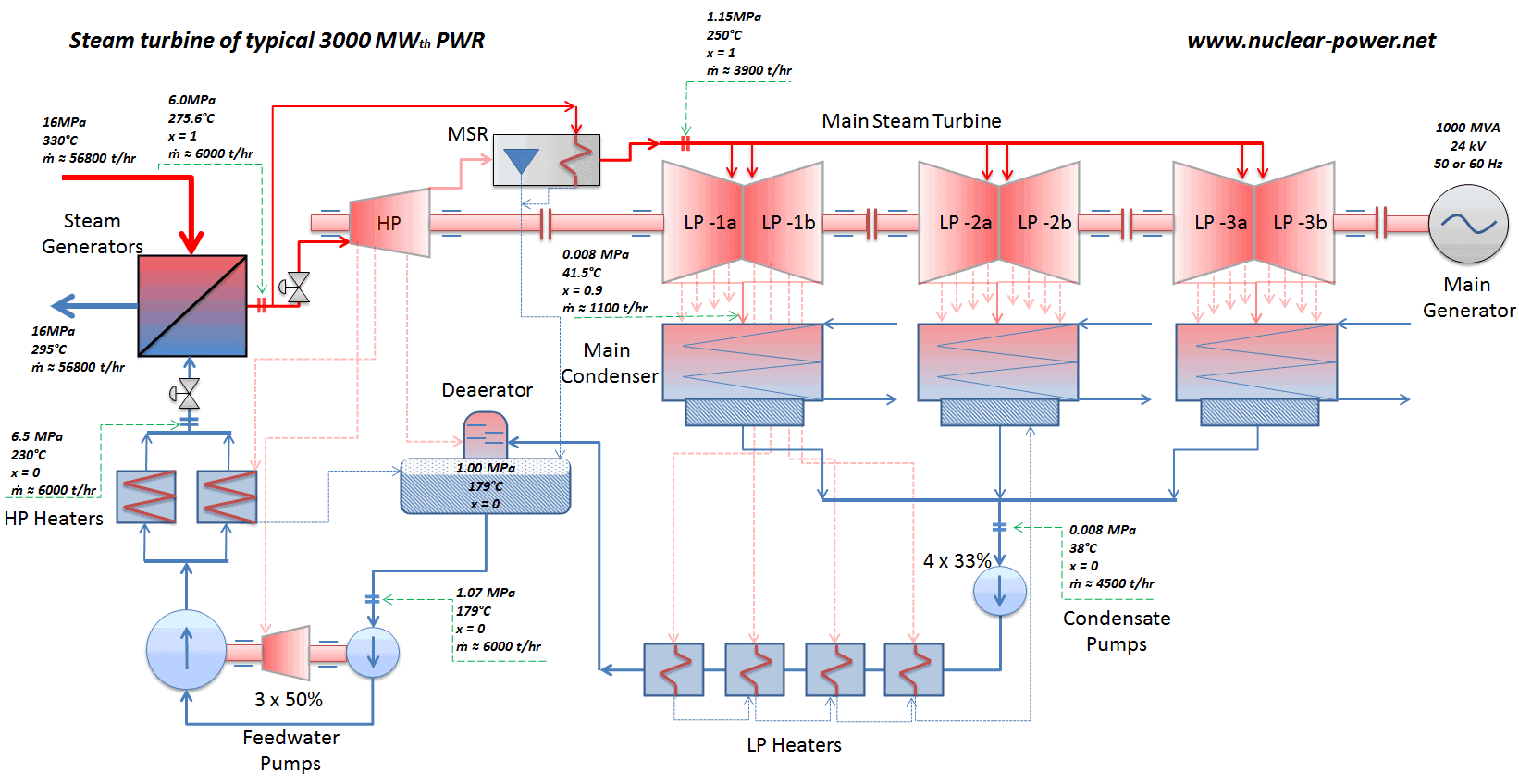
The power conversion system of typical PWR begins in the steam generators (boiler) in their shell sides. Steam generators are heat exchangers used to convert feedwater into steam from heat produced in a nuclear reactor core. The feedwater (secondary circuit) is heated from ~230°C 500°F (preheated fluid by regenerators) to the boiling point of that fluid (280°C; 536°F; 6,5MPa). Heat is transferred through the walls of these tubes to the lower pressure secondary coolant located on the secondary side of the exchanger where the coolant evaporates to pressurized steam (saturated steam 280°C; 536°F; 6,5 MPa). The saturated steam leaves the steam generator through a steam outlet and continues to the main steam lines and further to the steam turbine.
 These main steam lines are cross-tied (e.g. via steam collector pipe) near the turbine to ensure that the pressure difference between any of the steam generators does not exceed specific value thus maintaining system balance and ensuring uniform heat removal from the Reactor Coolant System (RCS). The steam flows through the main steam line isolation valves (MSIVs), which are very important from safety point of view, to the high pressure turbine. Directly at the inlet of the steam turbine, there are throttle-stop valves and control valves. Turbine control is achieved by varying these turbine valves openings. In the event of a turbine trip, the steam supply must be isolated very quickly, usually in the fraction of a second, so the stop valves must operate quickly and reliably.
Calculate the amount of primary coolant, which is required to evaporate 1 kg of feedwater in a typical steam generator. Assume that there are no energy losses, this is only idealized example.
Balance of the primary circuit
The hot primary coolant (water 330°C; 626°F; 16MPa) is pumped into the steam generator through primary inlet. The primary coolant leaves (water 295°C; 563°F; 16MPa) the steam generator through primary outlet.
hI, inlet = 1516 kJ/kg
=> ΔhI = -206 kJ/kg
hI, outlet = 1310 kJ/kg
Balance of the feedwater

The feedwater (water 230°C; 446°F; 6,5MPa) is pumped into the steam generator through the feedwater inlet. The feedwater (secondary circuit) is heated from ~230°C 446°F to the boiling point of that fluid (280°C; 536°F; 6,5MPa). Feedwater is then evaporated and the pressurized steam (saturated steam 280°C; 536°F; 6,5 MPa) leaves the steam generator through steam outlet and continues to the steam turbine.
hII, inlet = 991 kJ/kg
=> ΔhII = 1789 kJ/kg
hII, outlet = 2780 kJ/kg
Balance of the steam generator
Since the difference in specific enthalpies is less for primary coolant than for feedwater, it is obvious that the amount of primary coolant will be higher than 1kg. To produce of 1 kg of saturated steam from feedwater, about 1789/206 x 1 kg = 8.68 kg of primary coolant is required.
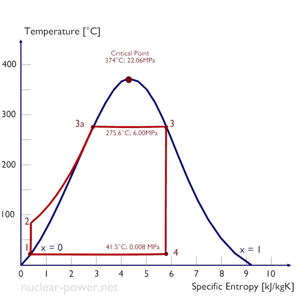
Isobaric heat addition (in a heat exchanger – boiler) – In this phase (between state 2 and state 3) there is a constant-pressure heat transfer to the liquid condensate from an external source, since the chamber is open to flow in and out. The feedwater (secondary circuit) is heated from to the boiling point (2 → 3a) of that fluid and then evaporated in the boiler (3a → 3). The net heat added is given by Qadd = H3 – H2
We hope, this article, From Boiler to Main Steam Lines – Evaporation, helps you. If so, give us a like in the sidebar. Main purpose of this website is to help the public to learn some interesting and important information about thermal engineering.