Main Parts of a Centrifugal Pump
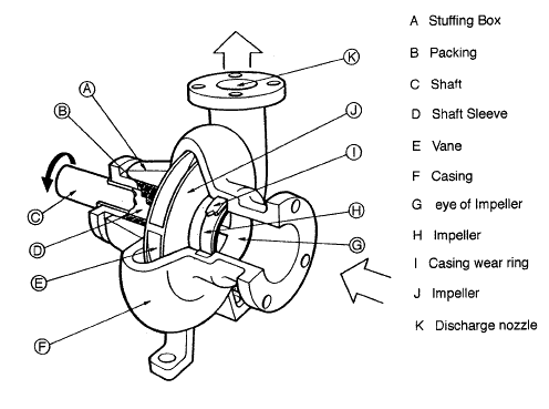
The wet end of the pump includes those parts that determine the hydraulic performance of pump. The two primary wet ends are the impeller and casing. In some cases the first radial bearing can be water lubricated. In this case also bearing can belongs to wet ends.
The mechanical end includes those parts that support the impeller within the casing. The mechanical end of the pump includes the pump shaft, sealing, bearings and shaft sleeve.
These components are designed to perform specific tasks:
 Impeller. Impeller is a rotor used to increase the kinetic energy of the flow.
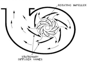
- Casing (Volute). The casing contains the liquid and acts as a pressure containment vessel that directs the flow of liquid in and out of the centrifugal pump. The volute is a curved funnel that increases in area as it approaches the discharge port. The volute of a centrifugal pump is the casing that receives the fluid being pumped by the impeller, slowing down the fluid’s rate of flow. Therefore, according to Bernoulli’s principle, the volute converts kinetic energy into pressure by reducing speed while increasing pressure. Some centrifugal pumps contain diffusers. A diffuser is a set of stationary vanes that surround the impeller. The diffuser directs the flow, allows a more gradual expansion and therefore increases the efficiency of the centrifugal pump.
- Shaft (Rotor). The impeller is mounted on a shaft. Shaft is a mechanical component for transmitting torque from the motor to the impeller.
- Shaft sealing. Centrifugal pumps are provided with packing rings or mechanical seal which helps prevent the leakage of the pumped liquid.
- Bearings. Bearings constrain relative motion of the shaft (rotor) and reduce friction between the rotating shaft and the stator. There are at least 5 common types of bearing, each of which operates on different principles:
- Plain bearing
- Rolling-element bearing
- Jewel bearing
- Fluid bearing
- Magnetic bearing
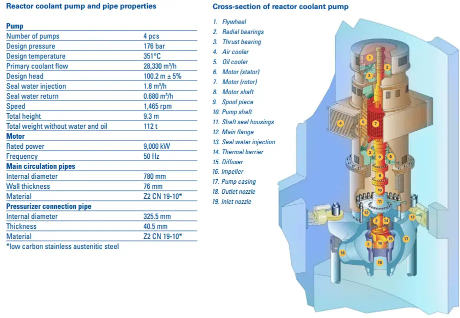
 Reactor coolant pumps (RCPs) are used to pump primary coolant around the primary circuit. The purpose of the reactor coolant pump is to provideforced primary coolant flow to remove and transfer the amount of heat generated in the reactor core.There are many designs of these pumps and there are many designs of primary coolant loops. There are significant differences between pumps for different reactor types. This article is focused on RCPs for pressurized water reactors. Most of PWRs use four RCPs in two or four loops design.
Generally reactor coolant pumps are powerful, they can consume up to 6 MW each and therefore they can be used for heating the primary coolant before a reactor startup.
Most of RCPs are vertical installed on a cold leg of a primary loop, but also a direct connection to a steam generator is possible. The reactor coolant enters the suction side of the pump at high pressure and temperature (~16MPa; 290°C; 554°F). The water is increased in velocity by the pump impeller. This increase in velocity is converted to pressure in the discharge volute. At the discharge of the reactor coolant pump, the reactor coolant pressure will be approximately 0,5MPa higher than the inlet pressure. After the coolant leaves the discharge side of the pump, it will enter the cold leg and continue to the reactor. The coolant will then pass through the nuclear core and through the fuel, where collects heat and is sent back to the steam generators.
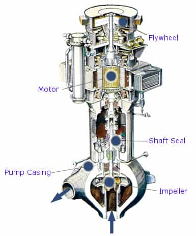
The main components of a reactor coolant pump
- Electric motor. The motor is a large, air or water (seal-less RCPs) cooled, induction motor.
- Impeller. Impeller is a rotor used to increase the pressure and flow of a coolant.
- Shaft (Rotor). Shaft is a mechanical component for transmitting torque from the motor to the impeller.
- Shaft seal package. Shaft seal package is used to prevent any water from leaking up the shaft into the containment.
- Bearings. Bearings constrain relative motion of the shaft (rotor) and reduce friction between the rotating shaft and the stator. RCPs usually use a combination of fluid dynamic bearings and hydrostatic bearings in the radial bearing assembly (water lubricated; close to the primary coolant) and oil lubricated bearings used in the thrust (axial) bearing assembly (in the motor section).
- Flywheel. The flywheel provides flow coastdown in case of loss of power.
- Auxilliary systems. Oil lubrication system, oil lift system, seal leakoff system, seal cooling system etc.
www.tvo.fi/uploads/julkaisut/tiedostot/ydinvoimalayks_OL3_ENG.pdf
Types of Impellers in Centrifugal Pumps
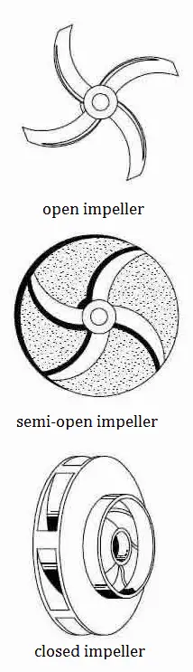
The impeller of a centrifugal pump can be of three basic types:
- Open impeller. Open impellers have the vanes free on both sides. Open impellers are structurally weak. They are typically used in small-diameter, inexpensive pumps and pumps handling suspended solids.
- Semi-open impeller. The vanes are free on one side and enclosed on the other. The shroud adds mechanical strength. They also offer higher efficiencies than open impellers. They can be used in medium-diameter pumps and with liquids containing small amounts of suspended solids. Because of minimization of recirculation and other losses, it is very important that a small clearance exists between the impeller vanes and the casing.
- Closed impeller. The vanes are located between the two discs, all in a single casting. They are used in large pumps with high efficiencies and low required Net Positive Suction Head. The centrifugal pumps with closed impeller are the most widely used pumps handling clear liquids. They rely on close-clearance wear rings on the impeller and on the pump casing. The closed impeller is a more complicated and expensive design not only because of the impeller, but the additional wear rings are needed.
The impeller blades can be:
- Backward-curved blade design (prefered design due to negative slope of performance curve)
- Radial blade design
- Forward-curved blade design (due to positive slope conditions this design can cause pump surge)
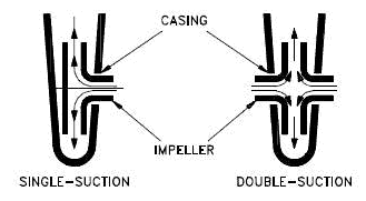
Impellers can be either:
- Single-suction. A single-suction impeller allows liquid to enter the center of the blades from only one direction.
- Double-suction. A double-suction impeller allows liquid to enter the center of the impeller blades from both sides simultaneously. This reduces forces exerted on the shaft.
 The output pressure slightly changes according to the design used. The blades may be open or closed. Also the diffuser may be fitted with fixed vanes to help guide the flow toward the exit. The energy transferred to the liquid corresponds to the velocity at the edge of the impeller. The faster the impeller revolves or the bigger the impeller is, the higher will the velocity head be.
In general, centrifugal pumps can be classified based on the manner in which fluid flows through the pump. It is not classification based on the impeller alone, but it is based on the design of pump casing and the impeller. The three types of flow through a centrifugal pump are:
- radial flow
- mixed flow (part radial, part axial)
- axial flow (propeller type)
We hope, this article, Main Part of a Centrifugal Pump, helps you. If so, give us a like in the sidebar. Main purpose of this website is to help the public to learn some interesting and important information about thermal engineering.