Centrifugal Pumps
How does it work?
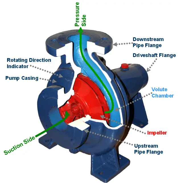
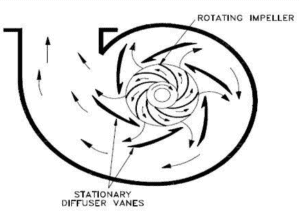
In the volute of the pump fluid enters the pump axially through the eye of the impeller (low pressure area) which rotates at high speed. As the impeller and blades rotate, they transfer momentum to incoming fluid. The fluid accelerates radially outward from the pump chasing and a vacuum is created at the impellers eye that continuously draws more fluid into the pump. As the fluid’s velocity increases its kinetic energy increases. Fluid of high kinetic energy is forced out of the impeller area and enters the volute. In the volute the fluid flows through a continuously increasing cross-sectional area, where the kinetic energy is converted into fluid pressure (according the Bernoulli’s principle).
The impeller blades are usually backward-curved, but there are also radial and forward-curved blade designs. The output pressure slightly changes according to the design used. The blades may be open or closed. Also the diffuser may be fitted with fixed vanes to help guide the flow toward the exit. The energy transferred to the liquid corresponds to the velocity at the edge of the impeller. The faster the impeller revolves or the bigger the impeller is, the higher will the velocity head be.

The Euler’s turbomachine equations are:
Shaft torque: Tshaft = ρQ(r2Vt2 – r1Vt1)
Water horsepower: Pw = ω . Tshaft = ρQ(u2Vt2 – u1Vt1)
Pump head: H = Pw / ρgQ = (u2Vt2 – u1Vt1)/g
where
- r1 and r2 are the diameters of the impeller at the inlet and outlet respectively.
- u1 and u2 are the absolute velocities of the impeller (u1 = r1 . ω) at the inlet and outlet respectively.
- Vt1 and Vt2 are the tangential velocities of the flow at the inlet and outlet respectively.
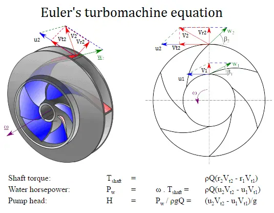
Euler’s turbomachine equations can be used to predict the impact of changing the impeller geometry on the head. It does not matter when we deal with a pump or with a turbine. If torque and angular velocity are of like sign, work is being done on the fluid (a pump or compressor). If torque and angular velocity are of opposite sign work is being extracted from the fluid (a turbine). Thus for the design aspect of turbines and pumps, the Euler equations are extremely useful.
- the design discharge
- water horsepower
- the pump head
of a centrifugal pump. This performance data will be derived from the Euler’s turbomachine equation:
Shaft torque: Tshaft = ρQ(r2Vt2 – r1Vt1)
Water horsepower: Pw = ω . Tshaft = ρQ(u2Vt2 – u1Vt1)
Pump head: H = Pw / ρgQ = (u2Vt2 – u1Vt1)/g
Given are the following data for a centrifugal water pump:
- diameters of the impeller at the inlet and outlet
- r1 = 10 cm
- r2 = 20 cm
- Speed = 1500 rpm (revolutions per minute)
- the blade angle at inlet β1 = 30°
- the blade angle at outlet β2 = 20°
- assume that the blade widths at inlet and outlet are: b1 = b2 = 4 cm.
Solution:
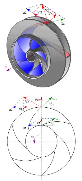
First, we have to calculate the radial velocity of the flow at the outlet. From the velocity diagram the radial velocity is equal to (we assume that the flow enters exactly normal to the impeller, so tangential component of velocity is zero):
Vr1 = u1 tan 30° = ω r1 tan 30° = 2π x (1500/60) x 0.1 x tan 30° = 9.1 m/s
Radial component of flow velocity determines how much the volume flow rate is entering the impeller. So when we know Vr1 at inlet, we can determine the discharge of this pump according to following equation. Here b1 means the blade width of the impeller at inlet.
Q = 2π.r1.b1.Vr1 = 2π x 0.1 x 0.04 x 9.1 = 0.229 m3/s
In order to calculate the water horsepower (Pw) required, we have to determine the outlet tangential flow velocity Vt2, because it has been assumed that the inlet tangential velocity Vt1 is equal to zero.
The outlet radial flow velocity follows from conservation of Q:
Q = 2π.r2.b2.Vr2 ⇒ Vr2 = Q / 2π.r2.b2 = 0.229 / (2π x 0.2 x 0.04) = 4.56 m/s
From the figure (velocity triangle) outlet blade angle, β2, can be easily represented as follows.
cot β2 = (u2 – Vt2) / Vr2
and therefore the outlet tangential flow velocity Vt2 is:
Vt2 = u2 – Vr2 . cot 20° = ω r2 – Vr2 . cot 20° = 2π x 1500/60 x 0.2 – 4.56 x 2.75 = 31.4 – 12.5 = 18.9 m/s.
The water horsepower required is then:
Pw = ρ Q u2 Vt2 = 1000 [kg/m3] x 0.229 [m3/s] x 31.4 [m/s] x 18.9 [m/s] = 135900 W = 135.6 kW
and the pump head is:
H ≈ Pw / (ρ g Q) = 135900 / (1000 x 9.81 x 0.229) = 60.5 m
Main Parts of a Centrifugal Pump
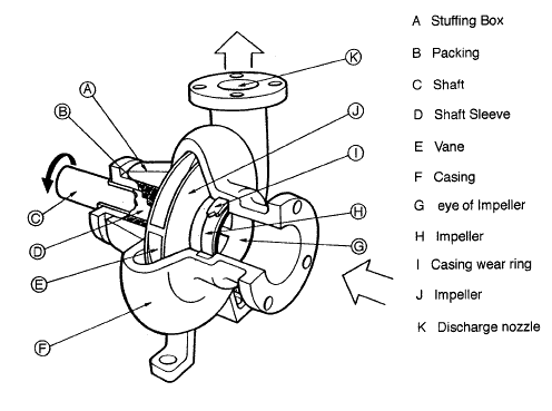
The wet end of the pump includes those parts that determine the hydraulic performance of pump. The two primary wet ends are the impeller and casing. In some cases the first radial bearing can be water lubricated. In this case also bearing can belongs to wet ends.
The mechanical end includes those parts that support the impeller within the casing. The mechanical end of the pump includes the pump shaft, sealing, bearings and shaft sleeve.
These components are designed to perform specific tasks:
 Impeller. Impeller is a rotor used to increase the kinetic energy of the flow.
- Casing (Volute). The casing contains the liquid and acts as a pressure containment vessel that directs the flow of liquid in and out of the centrifugal pump. The volute is a curved funnel that increases in area as it approaches the discharge port. The volute of a centrifugal pump is the casing that receives the fluid being pumped by the impeller, slowing down the fluid’s rate of flow. Therefore, according to Bernoulli’s principle, the volute converts kinetic energy into pressure by reducing speed while increasing pressure. Some centrifugal pumps contain diffusers. A diffuser is a set of stationary vanes that surround the impeller. The diffuser directs the flow, allows a more gradual expansion and therefore increases the efficiency of the centrifugal pump.
- Shaft (Rotor). The impeller is mounted on a shaft. Shaft is a mechanical component for transmitting torque from the motor to the impeller.
- Shaft sealing. Centrifugal pumps are provided with packing rings or mechanical seal which helps prevent the leakage of the pumped liquid.
- Bearings. Bearings constrain relative motion of the shaft (rotor) and reduce friction between the rotating shaft and the stator. There are at least 5 common types of bearing, each of which operates on different principles:
- Plain bearing
- Rolling-element bearing
- Jewel bearing
- Fluid bearing
- Magnetic bearing
Types of Impellers in Centrifugal Pumps
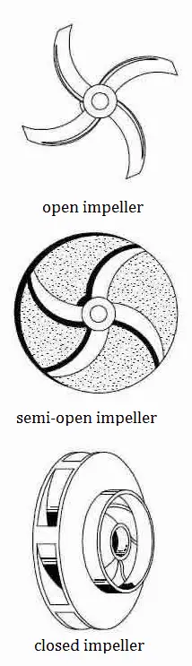
The impeller of a centrifugal pump can be of three basic types:
- Open impeller. Open impellers have the vanes free on both sides. Open impellers are structurally weak. They are typically used in small-diameter, inexpensive pumps and pumps handling suspended solids.
- Semi-open impeller. The vanes are free on one side and enclosed on the other. The shroud adds mechanical strength. They also offer higher efficiencies than open impellers. They can be used in medium-diameter pumps and with liquids containing small amounts of suspended solids. Because of minimization of recirculation and other losses, it is very important that a small clearance exists between the impeller vanes and the casing.
- Closed impeller. The vanes are located between the two discs, all in a single casting. They are used in large pumps with high efficiencies and low required Net Positive Suction Head. The centrifugal pumps with closed impeller are the most widely used pumps handling clear liquids. They rely on close-clearance wear rings on the impeller and on the pump casing. The closed impeller is a more complicated and expensive design not only because of the impeller, but the additional wear rings are needed.
The impeller blades can be:
- Backward-curved blade design (prefered design due to negative slope of performance curve)
- Radial blade design
- Forward-curved blade design (due to positive slope conditions this design can cause pump surge)
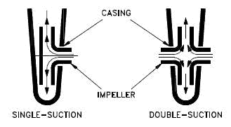
Impellers can be either:
- Single-suction. A single-suction impeller allows liquid to enter the center of the blades from only one direction.
- Double-suction. A double-suction impeller allows liquid to enter the center of the impeller blades from both sides simultaneously. This reduces forces exerted on the shaft.
The output pressure slightly changes according to the design used. The blades may be open or closed. Also the diffuser may be fitted with fixed vanes to help guide the flow toward the exit. The energy transferred to the liquid corresponds to the velocity at the edge of the impeller. The faster the impeller revolves or the bigger the impeller is, the higher will the velocity head be.
In general, centrifugal pumps can be classified based on the manner in which fluid flows through the pump. It is not classification based on the impeller alone, but it is based on the design of pump casing and the impeller. The three types of flow through a centrifugal pump are:
- radial flow
- mixed flow (part radial, part axial)
- axial flow (propeller type)
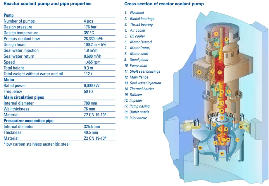
 Reactor coolant pumps (RCPs) are used to pump primary coolant around the primary circuit. The purpose of the reactor coolant pump is to provideforced primary coolant flow to remove and transfer the amount of heat generated in the reactor core.There are many designs of these pumps and there are many designs of primary coolant loops. There are significant differences between pumps for different reactor types. This article is focused on RCPs for pressurized water reactors. Most of PWRs use four RCPs in two or four loops design.
Generally reactor coolant pumps are powerful, they can consume up to 6 MW each and therefore they can be used for heating the primary coolant before a reactor startup.
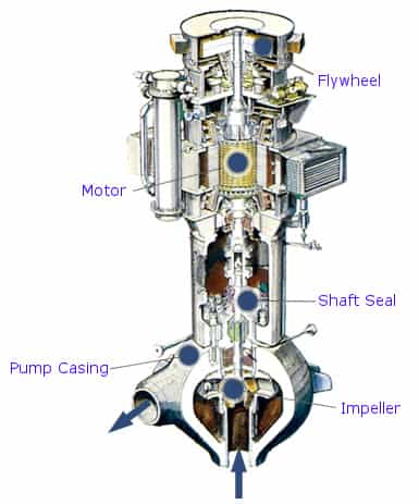
Most of RCPs are vertical installed on a cold leg of a primary loop, but also a direct connection to a steam generator is possible. The reactor coolant enters the suction side of the pump at high pressure and temperature (~16MPa; 290°C; 554°F). The water is increased in velocity by the pump impeller. This increase in velocity is converted to pressure in the discharge volute. At the discharge of the reactor coolant pump, the reactor coolant pressure will be approximately 0,5MPa higher than the inlet pressure. After the coolant leaves the discharge side of the pump, it will enter the cold leg and continue to the reactor. The coolant will then pass through the nuclear core and through the fuel, where collects heat and is sent back to the steam generators.
The main components of a reactor coolant pump
- Electric motor. The motor is a large, air or water (seal-less RCPs) cooled, induction motor.
- Impeller. Impeller is a rotor used to increase the pressure and flow of a coolant.
- Shaft (Rotor). Shaft is a mechanical component for transmitting torque from the motor to the impeller.
- Shaft seal package. Shaft seal package is used to prevent any water from leaking up the shaft into the containment.
- Bearings. Bearings constrain relative motion of the shaft (rotor) and reduce friction between the rotating shaft and the stator. RCPs usually use a combination of fluid dynamic bearings and hydrostatic bearings in the radial bearing assembly (water lubricated; close to the primary coolant) and oil lubricated bearings used in the thrust (axial) bearing assembly (in the motor section).
- Flywheel. The flywheel provides flow coastdown in case of loss of power.
- Auxilliary systems. Oil lubrication system, oil lift system, seal leakoff system, seal cooling system etc.
www.tvo.fi/uploads/julkaisut/tiedostot/ydinvoimalayks_OL3_ENG.pdf
Performance Characteristics of Centrifugal Pumps
Although the theory of centrifugal pumps gives many qualitative results, the most important indicator of a pump’s performance lies in extensive hydraulic testing.
In industry, characteristics of all pumps are usually read from its Q-H curve or performance curve (flow rate – height). As can be seen, the performance charts use a discharge – Q (usually in m3/h) and pump head – H (usually in m) as basic performance variables.
System Head
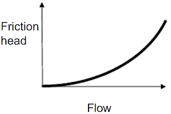 In the chapter on head loss, it was determined that both major losses and minor losses in piping systems are proportional to the square of the flow velocity. It is obvious the system head loss must be directly proportional to the square of the volumetric flow rate, because the volumetric flow rate is directly proportional to the flow velocity.
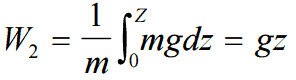
It must be added that the open hydraulic systems contains not only the friction head, but also the elevation head, which must be considered. The elevation head (static head) represents the potential energy of a fluid due to its elevation above a reference level.
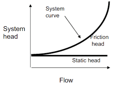 In many cases the total head of a system is a combination of elevation head and friction head as shown in the figure.
In nuclear engineering most of hydraulic systems are closed hydraulic loops and these systems only have friction head (no static head).
Summary:
- Head loss of hydraulic system is divided into two main categories:
- Major Head Loss – due to friction in straight pipes
- Minor Head Loss – due to components as valves, bends…
- Darcy’s equation can be used to calculate major losses.
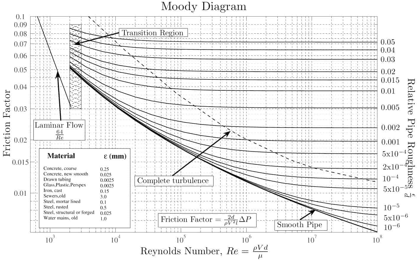
- The friction factor for fluid flow can be determined using a Moody chart.
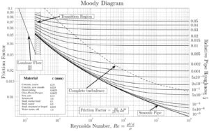
- The friction factor for laminar flow is independent of roughness of the pipe’s inner surface. f = 64/Re
- The friction factor for turbulent flow depends strongly on the relative roughness. It is determined by the Colebrook equation. It must be noted, at very large Reynolds numbers, the friction factor is independent of the Reynolds number.
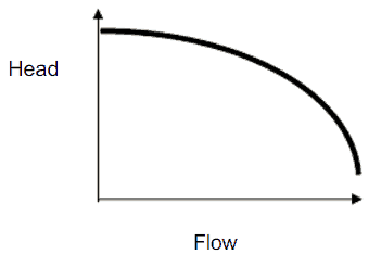
Pump Head – Performance Curve
In fluids dynamics the term pump head is used to measure the kinetic energy which a pump creates. Head is a measurement of the height of the incompressible fluid column the pump could create from the kinetic energy, that the pump gives to the liquid. The head and flow rate determine the performance of a pump, which is graphically shown in the figure as the performance curve or pump characteristic curve. The main reason for using head instead of pressure to determine the performance of a centrifugal pump is that the height of the fluid column is not dependent on the specific gravity (weight) of the liquid, while the pressure from a pump will change. In terms of pressure the pump head (ΔPpump) is difference between system back pressure and the inlet pressure of the pump.
When a centrifugal pump is operating at a constant angular velocity, an increase in the system head (back pressure) on the flowing stream causes a reduction in the volumetric flow rate that the centrifugal pump can maintain.
The relationship between the pump head and the volumetric flow rate (Q), that a centrifugal pump can maintain, is dependent on various physical characteristics of the pump as:
- the power supplied to the pump
- the angular velocity of shaft
- the type and diameter of the impeller
and the used fluid:
- fluid density
- fluid viscosity
This relationship is very complicated and its analysis lies in extensive hydraulic testing of certain centrifugal pump. As can be seen from the picture below.
Operating Characteristics of a Hydraulic Loop
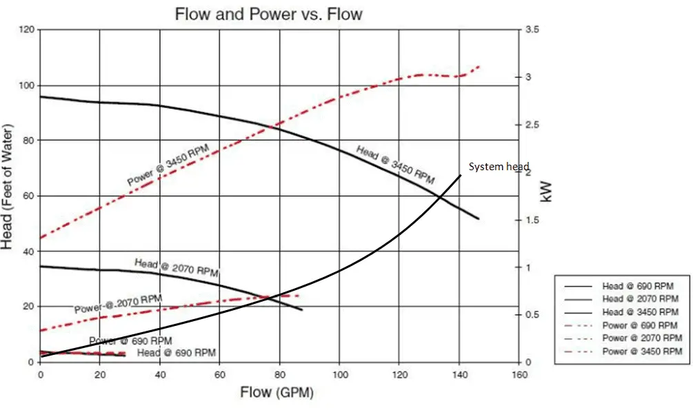
When we put together the frictional characteristics (system head) of a hydraulic loop and the performance curve the result will describe the characteristics of entire system (e.g. one loop of primary circuit). The following figure shows typical performance curve for a centrifugal pump related to the system frictional head.
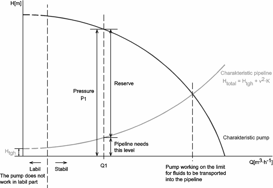
Pump head, on the vertical axis, is the difference between system back pressure and the inlet pressure of the pump (ΔPpump). Volumetric flow rate (Q ), on the horizontal axis, is the rate at which fluid is flowing through the pump. As can be seen, the head is approximately constant at low discharge and then drops to zero at Qmax. At low discharge the characteristics can be unstable (with positive slope of pump head). This is undesirable characteristics, because an unstable pump may start to oscillate between the two possible combinations of flow rate and the pipeline can vibrate.
At flow rate Q1 the pump gains more head than consumes the frictional losses, therefore the flow rate through the system will increase. The flow rate will stabilize itself at the point, where the frictional losses intersect the pump characteristics.
In order to characterize the performance of centrifugal pumps, the following terms are defined:
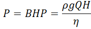
where:
- P is the input power required (W)
- BHP is the brake horsepower
- ρ is the fluid density (kg/m3 )
- g is the standard acceleration of gravity (9.81 m/s2 )
- H is the net pump head added to the flow (m)
- Q is the flow rate (m3 /s)
- η is the efficiency of the pump
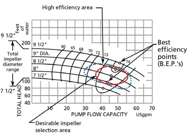
The internal losses are caused by fluid friction in the impeller due to rapid change in flow direction and change in velocities throughout the pump. The external losses are caused by mechanical losses in seals and bearings. All points to the right or left of the BEP have a lower efficiency. Pumps should be sized as close as possible to its best efficiency point or flow rate. This not only makes the pump more efficient but also improves the reliability of the pump. Note that total efficiency is never realized because of mechanical and hydraulic losses incurred in the pump.
Impeller design is the most significant factor for determining the BEP of a pump because it determines how efficiently power (brake horsepower or BHP) is transmitted to the liquid being pumped. A properly designed impeller optimizes flow while minimizing turbulence and maximizing efficiency.
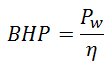
In the metric system kilowatts (kW) are used. Due to hydraulic, mechanical and volumetric losses in a pump the actual or water horsepower available for work on the fluid is less than the total horsepower supplied.
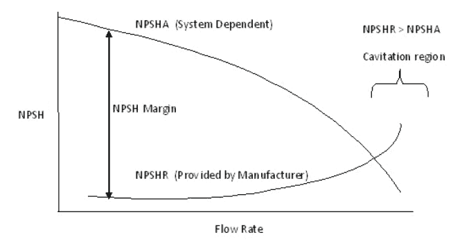
In general, there are two suction heads defined in hydraulics:
- NPSH Available (NPSHa): The absolute pressure at the suction port of the pump. NPSHa is a function of water temperature. As the inlet temperature increases NPSHa decreases, because the saturation pressure decreases.
- NPSH Required (NPSHR): The minimum pressure required at the suction port of the pump to keep the pump from cavitating. NPSHa is not a function of water temperature.
NPSHA is a function of your system and must be calculated, whereas NPSHR is a function of the pump and must be provided by the pump manufacturer. During operation the available NPSH must be maintained at a level greater than the NPSH required by the pump manufacturer. It has been found that cavitation rates increase rapidly with the increase in the volume flow rate. This can be seen from the picture, as volume flow rate increases, NPSH required increases, but the available NPSH decreases.
How to increase NPSH available?
To avoid suction cavitation, NPSH available must be increased as much as possible. The only way to increase NPSH available is to increase the pressure at the pump inlet:
- Lower the pump level
- Raise the reservoir level
- Reduction of motor RPM if possible
- Reduce minor losses upstream of the pump
- Reduce major losses upstream of the pump
- Shorten the length of pipe
- Use a smoother pipe
- Increase of the diameter of the eye of the impeller
- Use of a booster pump to feed the principal pump.
Series Operation of Centrifugal Pumps (Booster)
In order to increase the volumetric flow rate in a system or to compensate for large major or minor losses, centrifugal pumps are often used in parallel or in series.
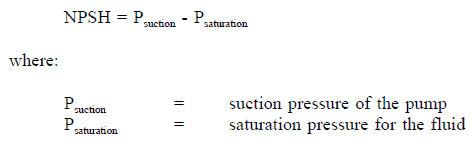
Series operation of centrifugal pumps is used to overcome large system head loss, or to gain large pressure increase when liquid is injected into very high pressure system (e.g. High Pressure Safety Injection Systems in PWRs, where multi-stage pumps are used).
When a centrifugal pump is operated in a closed loop, the resulting discharge pressure will be simply the sum of the suction pressure and the pressure normally developed by the pump when operating at zero suction pressure. Therefore it is well suited for use as a booster pump when operated in series. The head produced by two or more pumps is equal to the sum of the individual heads. The volumetric flow rate from the inlet of the first pump to the outlet of the second remains the same. In practical application the multi-stage pumps (multiple impeller pump) are build in order to reach higher pump head.
Parallel Operation of Centrifugal Pumps
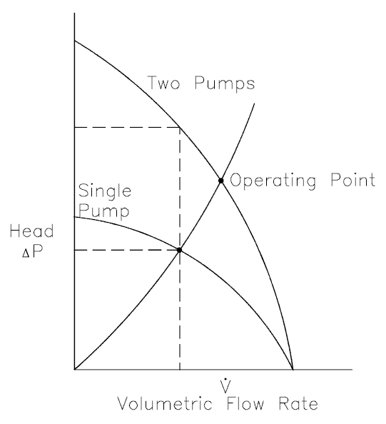
In order to increase the volumetric flow rate in a system or to compensate for large major or minor losses, centrifugal pumps are often used in parallel or in series.
Parallel operation of centrifugal pumps is used to increase flow rate through the system. Pumps operating in parallel take their suction from a common header and discharge into a common discharge. While head changes only slightly, flow is almost doubled at any given point. It must be noted the volumetric flow rate is actually less than twice the flow rate achieved by using a single pump. This is caused by a greater system head loss resulting from higher flow rate.
Major Failure Modes of Centrifugal Pumps
Since centrifugal pumps are one of the world’s most widely used type of pump, their operational parameters and also their vulnerabilities are well known. This article reviews the major failure modes that are found in centrifugal pumps. In general, pump failures result in operational changes that reduce efficiency or may result in a breakdown of the pump. Reliability of hydraulic systems and also centrifugal pumps is of the highest importance in nuclear engineering.
The failure modes of centrifugal pumps can be grouped into three categories:
Hydraulic Failure Modes
- Cavitation. Cavitation is, in many cases, an undesirable occurrence. In centrifugal pumps, cavitation causes, damage to components (erosion of the material), vibrations, noise and a loss of efficiency.
- Pressure Pulsation. Pressure pulsations are fluctuations in the basic pressure. For high-head pumps, suction and discharge pressure pulsations may cause instability of pump controls, vibration of suction and discharge piping, and high levels of pump noise.
- Pump Recirculation. A pump operating at lower capacity than design limits can suffer from recirculation which occurs internally in the pumps. Pump recirculation can cause surging and cavitation even when the available NPSHa exceeds the supplier’s NPSHr by considerable margin.
- Radial and Axial Thrust. High radial thrust that results in excessive shaft deflections may lead to persistent packing or mechanical seal problems, and possibly, shaft failure. Axial thrust is imposed along the shaft axis. High axial thrust may impose an excessive load on the bearing.
Mechanical Failure Modes
- Shaft Seizure or Break
- Bearing Failure
- Seal Failure
- Vibrations
- Fatigue
Other Failure Modes
- Erosion
- Corrosion
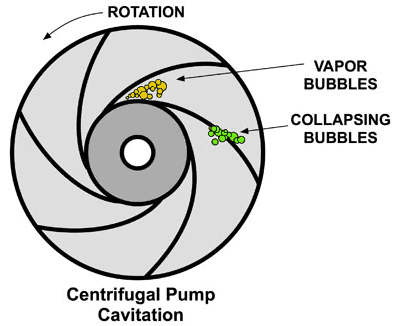
Cavitation in Centrifugal Pumps
 Major places where cavitation occurs are in pumps, on impellers or propellers. In centrifugal pumps, cavitation results from a reduction in suction pressure, an increase in suction temperature, or an increase in the flow rate above that for which the pump has been designed.
There are two basic types of pump cavitation:
Typical causes of suction cavitation:
- Pump is running too far right on the pump curve
- Poor suction conditions (NPSH requirements)
- Blockage in the pipe on suction side
- Inappropriate piping design
- Clogged filters or strainers
To prevent this type of cavitation, the Net Positive Suction Head available (NPSHa) in the system must be higher than the required NPSH of the pump. This problem is typical for suction cavitation and therefore this type of cavitation is also called inadequate NPSHa cavitation.
Besides the change of the pump, problems with suction cavitation can be also solved by:
- Lowering the temperature
- Reduction of motor RPM if possible
- Increase of the diameter of the eye of the impeller
- Use of an impeller inducer.
- Use of two parallel pumps with lower capacity.
- Use of a booster pump to feed the principal pump.
Special case of cavitation occurs at the suction side as a result of inappropriate piping in suction line. Use of restrictions, sharp elbows and other hydraulic equipment can turbulize the flow this can contribute to cavitation formation.
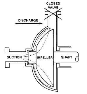
This type of cavitation originates from two sources. First, this internal circulation (from high-pressure zones into low-pressure zones) is forced through the clearance between the impeller and the pump housing at high velocity resulting in the formation of a low pressure region (as a result of Bernoulli’s principle) in which cavitation can occur. Second, the liquid is circulating inside the volute of the pump and it rapidly overheats.
In both cases, cavitation have similar consequences. The implosion of bubbles trigger intense shockwaves, causing premature wear of the impeller tips and pump housing. In extreme case, discharge cavitation can cause the impeller shaft to break.
Typical causes of discharge cavitation:
- Pump is running too far left on the pump curve
- Blockage in the pipe on discharge side
- Clogged filters or strainers
- Inappropriate piping design
Cavitation Number
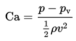
The Cavitation Number (Ca) or Cavitation Parameter is a dimensionless number used in flow calculations. It is conventional to characterize how close the pressure in the liquid flow is to the vapor pressure (and therefore the potential for cavitation) by means of the cavitation number.
The Cavitation Number can be expressed as:
where
CA = Cavitation Number
p = local pressure (Pa)
pv = vapor pressure of the fluid (Pa)
ρ = density of the fluid (kg/m3)
v = velocity of fluid (m/s)
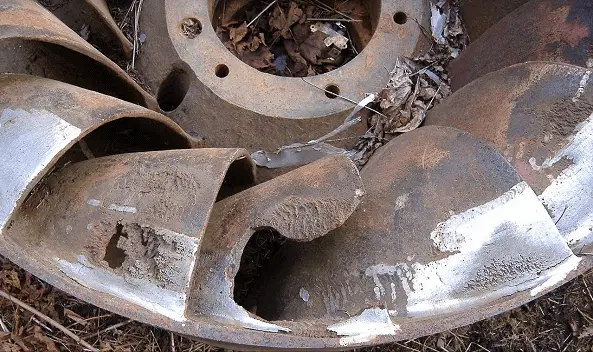
Cavitation Damage
Cavitation is, in many cases, an undesirable occurrence. In centrifugal pumps, cavitation causes damage to components (erosion of the material), vibrations, noise and a loss of efficiency.
https://commons.wikimedia.org/wiki/File:Turbine_Francis_Worn.JPG
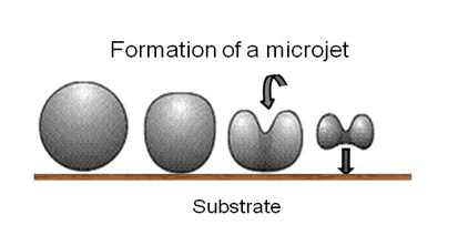
Perhaps the most important engineering problem caused by cavitation is the material damage that cavitation bubbles can cause when they collapse in the vicinity of a solid surface. Cavitation bubbles collapse is a violent process that generates highly localized shock waves and microjets. They force energetic liquid into very small volumes, thereby creating spots of high temperature and these intense disturbances generate highly localized and transient surface stresses to a solid surface. Signs of erosion will appear as pitting due to the waterhammering action of the collapsing vapour bubbles. It has been found that cavitation damage rates increase rapidly with the increase in the volume flow rate.
Softer materials can be damaged even by short-term occurrance of cavitation. Individual pits can be observed after a single bubble collapse. Therefore harder materials are used for centrifugal pumps. But with the harder materials used in most applications, the cyclic stress due to repeated collapses can cause local surface fatigue failure. Thus cavitation damage to metals usually has the appearance of fatigue failure.
 When the cavitation bubbles collapse, they force energetic liquid into very small volumes, thereby creating spots of high temperature and emitting shock waves, the latter of which are a source of noise. Although the collapse of a small cavity is a relatively low-energy event, highly localized collapses can erode metals, such as steel, over time. The pitting caused by the collapse of cavities produces great wear on components and can dramatically shorten a propeller or pump’s lifetime.
Cavitation is usually accompanied also by:
- Noise. Typical noise is caused by collapsing cavities. The level of the noise that results from cavitation is a measure of the severity of the cavitation.
- Vibration. Pump vibrations due to cavitation are characteristically low frequency vibrations, usually found in the 0 to 10 Hz range.
- Reduction in pump efficiency. A decrease in efficiency of the pump is a more reliable sign of cavitation occurring.
We hope, this article, Centrifugal Pump, helps you. If so, give us a like in the sidebar. Main purpose of this website is to help the public to learn some interesting and important information about thermal engineering.