Whether the flow will be plug or slug flow, it is dependent especially on the void fraction that causes agglomeration of bubbles into larger plugs and slugs. Thermal Engineering
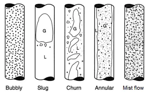
Slug Flow – Vertical Tubes
Increasing void fraction in bubbly flow causes agglomeration of bubbles into larger plugs and slugs. These slugs are similar in dimension to the tube diameter. These slugs travel at a speed that is a substantial fraction of the gas velocity and occur intermittently. Since these large gas slugs are separated from one another by slugs of liquid, they cause large pressure and liquid flow rate fluctuations. In some cases, a downward flow can be observed near the tube wall, even though the net flow of fluid is upward. This is caused by the gravitational force.
Sketches of flow regimes for two-phase flow in a vertical pipe. Source: Weisman, J. Two-phase flow patterns. Chapter 15 in Handbook of Fluids in Motion, Cheremisinoff N.P., Gupta R. 1983, Ann Arbor Science Publishers.
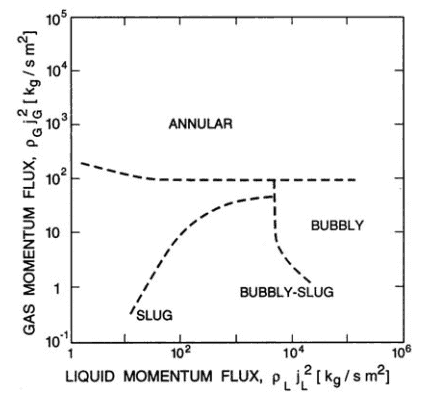
The vertical flow regime map of Hewitt and Roberts (1969) for flow in a 3.2cm diameter tube, validated for both air/water flow at atmospheric pressure and steam/water flow at high pressure. Source: Brennen, C.E., Fundamentals of Multiphase Flows, Cambridge University Press, 2005, ISBN 0521 848040
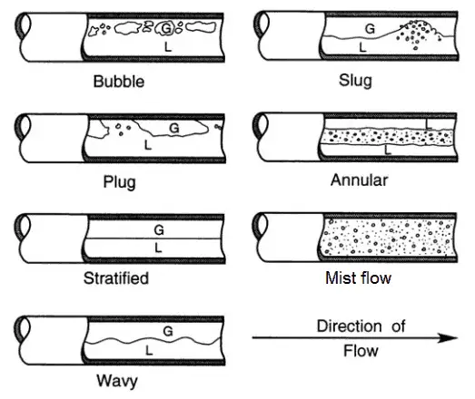
Plug Flow and Slug Flow – Horizontal Tubes
Further increasing in the gas velocity causes, that waves reach the top of the tube. Whether the flow will be plug or slug flow, it is dependent especially on the void fraction that causes agglomeration of bubbles into larger plugs and slugs. In the plug flow the diameters of the bubbles are smaller than the tube. Slugs are similar in dimension to the tube diameter. The slugs travel at a speed that is a substantial fraction of the gas velocity and occur intermittently. Since these large gas slugs are separated from one another by slugs of liquid, they cause large pressure and liquid flow rate fluctuations.
Sketches of flow regimes for two-phase flow in a horizontal pipe. Source: Weisman, J. Two-phase flow patterns. Chapter 15 in Handbook of Fluids in Motion, Cheremisinoff N.P., Gupta R. 1983, Ann Arbor Science Publishers.
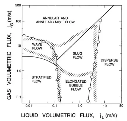
A flow regime map for the flow of an air/water mixture in a horizontal, 2.5cm diameter pipe at 25◦C and 1bar. Solid lines and points are experimental observations of the transition conditions while the hatched zones represent theoretical predictions. Source: Mandhane, J.M., Gregory, G.A. and Aziz, K.A. (1974). A flow pattern map for gas-liquid flow in horizontal pipes. Int. J. Multiphase Flow
References:
Reactor Physics and Thermal Hydraulics:
J. R. Lamarsh, Introduction to Nuclear Reactor Theory, 2nd ed., Addison-Wesley, Reading, MA (1983).
J. R. Lamarsh, A. J. Baratta, Introduction to Nuclear Engineering, 3d ed., Prentice-Hall, 2001, ISBN: 0-201-82498-1.
W. M. Stacey, Nuclear Reactor Physics, John Wiley & Sons, 2001, ISBN: 0- 471-39127-1.
Todreas Neil E., Kazimi Mujid S. Nuclear Systems Volume I: Thermal Hydraulic Fundamentals, Second Edition. CRC Press; 2 edition, 2012, ISBN: 978-0415802871
Zohuri B., McDaniel P. Thermodynamics in Nuclear Power Plant Systems. Springer; 2015, ISBN: 978-3-319-13419-2
Moran Michal J., Shapiro Howard N. Fundamentals of Engineering Thermodynamics, Fifth Edition, John Wiley & Sons, 2006, ISBN: 978-0-470-03037-0
Kleinstreuer C. Modern Fluid Dynamics. Springer, 2010, ISBN 978-1-4020-8670-0.
U.S. Department of Energy, THERMODYNAMICS, HEAT TRANSFER, AND FLUID FLOW. DOE Fundamentals Handbook, Volume 1, 2 and 3. June 1992.
White Frank M., Fluid Mechanics, McGraw-Hill Education, 7th edition, February, 2010, ISBN: 978-0077422417
See also:
Two-phase Flow
We hope, this article, Plug Flow – Slug Flow, helps you. If so, give us a like in the sidebar. Main purpose of this website is to help the public to learn some interesting and important information about thermal engineering.