Internal Flow
In fluid dynamics, internal flow is a flow for which the fluid is confined by a surface. Detailed knowledge of behaviour of internal flow regimes is of importance in engineering, because circular pipes can withstand high pressures and hence are used to convey liquids. Non-circular ducts are used to transport low-pressure gases, such as air in cooling and heating systems. The internal flow configuration is a convenient geometry for heating and cooling fluids used in energy conversion technologies such as nuclear power plants.
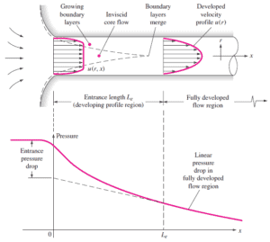
For internal flow regime an entrance region is typical. In this region a nearly inviscid upstream flow converges and enters the tube. To characterize this region the hydrodynamic entrance length is introduced and is approximately equal to:
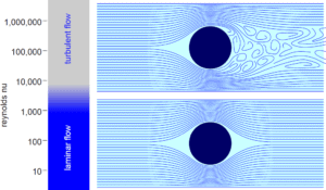
The maximum hydrodynamic entrance length, at ReD,crit = 2300 (laminar flow), is Le = 138d, where D is the diameter of the pipe. This is the longest development length possible. In turbulent flow, the boundary layers grow faster, and Le is relatively shorter. For any given problem, Le / D has to be checked to see if Le is negligible when compared to the pipe length. At a finite distance from the entrance, the entrance effects may be neglected, because the boundary layers merge and the inviscid core disappears. The tube flow is then fully developed.
Hydraulic Diameter
To further simplify calculations and enlarge the range of applications, the hydraulic diameter is introduced:
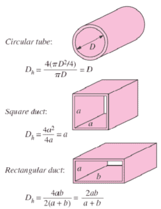 The hydraulic diameter, Dh, is a commonly used term when handling flow in non-circular tubes and channels. The hydraulic diameter transforms non-circular ducts into pipes of equivalent diameter. Using this term, one can calculate many things in the same way as for a round tube. In this equation A is the cross-sectional area, and P is the wetted perimeter of the cross-section.
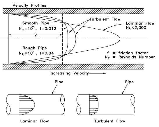
Most industrial flows, especially those in nuclear engineering are turbulent. For single straight pipe analysis, assuming unidirectional flow, geometric and kinematic pipe-design problems rely on the Moody chart and can be grouped as follows:
- Evaluate the necessary pump characteristics (Q-H characteristics) based on the computed pressure drop Δp in order to convey a given maximum flow rate.
- Calculate a specified pressure drop for the pipe of diameter D, of given pipe length and flow rate. This problem requires an iterative procedure because the Reynolds number, and hence the friction factor f, is not known.
- Calculate the flow rate Q for a given pipe geometry (D, L, ε/D) and pressure drop, where ε/D is the relative surface roughness. This problem requires an iterative procedure because the Reynolds number, and hence the friction factor f, is not known.
Example: Reynolds number for a primary piping and a fuel bundle
It is an illustrative example, following data do not correspond to any reactor design.
Pressurized water reactors are cooled and moderated by high-pressure liquid water (e.g. 16MPa). At this pressure water boils at approximately 350°C (662°F). Inlet temperature of the water is about 290°C (⍴ ~ 720 kg/m3). The water (coolant) is heated in the reactor core to approximately 325°C (⍴ ~ 654 kg/m3) as the water flows through the core.
The primary circuit of typical PWRs is divided into 4 independent loops (piping diameter ~ 700mm), each loop comprises a steam generator and one main coolant pump. Inside the reactor pressure vessel (RPV), the coolant first flows down outside the reactor core (through the downcomer). From the bottom of the pressure vessel, the flow is reversed up through the core, where the coolant temperature increases as it passes through the fuel rods and the assemblies formed by them.
Assume:
- the primary piping flow velocity is constant and equal to 17 m/s,
- the core flow velocity is constant and equal to 5 m/s,
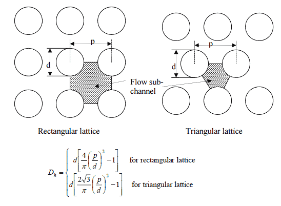
- the hydraulic diameter of the fuel channel, Dh, is equal to 2 cm
- the kinematic viscosity of the water at 290°C is equal to 0.12 x 10⁻⁶ m2/s
See also: Example: Flow rate through a reactor core
Determine
- the flow regime and the Reynolds number inside the fuel channel
- the flow regime and the Reynolds number inside the primary piping
The Reynolds number inside the primary piping is equal to:
ReD = 17 [m/s] x 0.7 [m] / 0.12×10⁻⁶ [m2/s] = 99 000 000
This fully satisfies the turbulent conditions.
The Reynolds number inside the fuel channel is equal to:
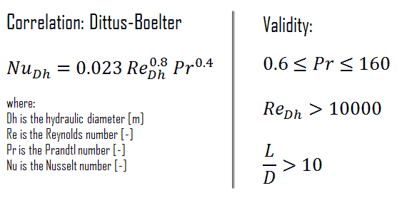
ReDH = 5 [m/s] x 0.02 [m] / 0.12×10⁻⁶ [m2/s] = 833 000
This also fully satisfies the turbulent conditions.
We hope, this article, Internal Flow, helps you. If so, give us a like in the sidebar. Main purpose of this website is to help the public to learn some interesting and important information about thermal engineering.
