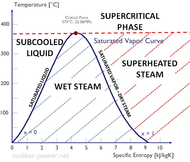
Saturation Vapor Curve
Source: wikipedia.org CC BY-SA
See also: Steam
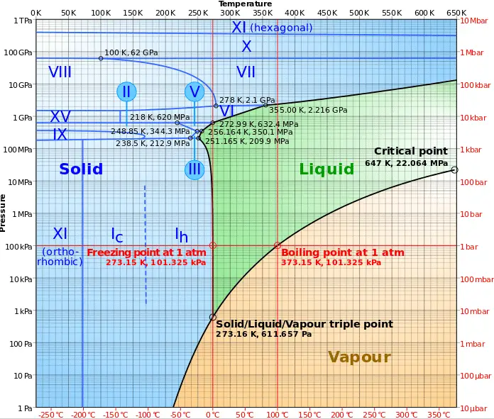
As can be seen from the phase diagram of water, in the two-phase regions (e.g. on the border of vapor/liquid phases), specifying temperature alone will set the pressure and specifying pressure will set the temperature.
- The saturation vapor curve is the curve separating the two-phase state and the superheated vapor state in the T-s diagram.
- The saturated liquid curve is the curve separating the subcooled liquid state and the two-phase state in the T-s diagram.
Typically most of nuclear power plants operates multi-stage condensing steam turbines. In these turbines the high-pressure stage receives steam (this steam is nearly saturated steam – x = 0.995 – point C at the figure) from a steam generator and exhaust it to moisture separator-reheater (point D). The steam must be reheated or superheated in order to avoid damages that could be caused to blades of steam turbine by low quality steam. High content of water droplets can cause the rapid impingement and erosion of the blades which occurs when condensed water is blasted onto the blades. To prevent this, condensate drains are installed in the steam piping leading to the turbine. The reheater heats the steam (point D) and then the steam is directed to the low-pressure stage of steam turbine, where expands (point E to F). The exhausted steam is at a pressure well below atmospheric, and is in a partially condensed state (point F), typically of a quality near 90%.
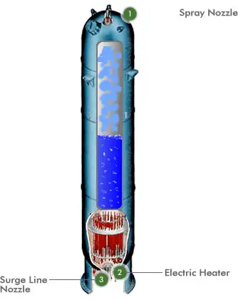
A pressurizer is a component of a pressurized water reactor. Pressure in the primary circuit of PWRs is maintained by a pressurizer, a separate vessel that is connected to the primary circuit (hot leg) and partially filled with water which is heated to the saturation temperature (boiling point) for the desired pressure by submerged electrical heaters. Temperature in the pressurizer can be maintained at 350 °C (662 °F), which gives a subcooling margin (the difference between the pressurizer temperature and the highest temperature in the reactor core) of 30 °C. Subcooling margin is very important safety parameter of PWRs, since the boiling in the reactor core must be excluded. The basic design of the pressurized water reactor includes such requirement that the coolant (water) in the reactor coolant system must not boil. To achieve this, the coolant in the reactor coolant system is maintained at a pressure sufficiently high that boiling does not occur at the coolant temperatures experienced while the plant is operating or in an analyzed transient.
Functions
Pressure in the pressurizer is controlled by varying the temperature of the coolant in the pressurizer. For these purposes two systems are installed. Water spray system and electrical heaters system. Volume of the pressurizer (tens of cubic meters) is filled with water on saturation parameters and steam. The water spray system (relatively cool water – from cold leg) can decrease the pressure in the vessel by condensing the steam on water droplets sprayed in the vessel. On the other hand the submerged electrical heaters are designed to increase the pressure by evaporation the water in the vessel. Water pressure in a closed system tracks water temperature directly; as the temperature goes up, pressure goes up.
We hope, this article, Saturation Vapor Curve, helps you. If so, give us a like in the sidebar. Main purpose of this website is to help the public to learn some interesting and important information about thermal engineering.