Learn how a hydraulic ram uses fluid pressure and area differences to amplify force in engineering applications like lifts and presses.
Understanding the Hydraulic Ram: Generating Force
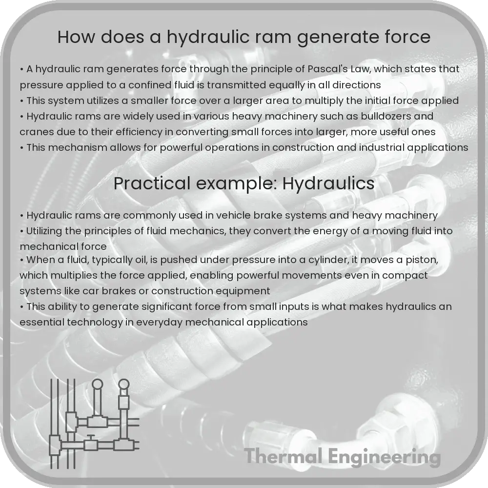
A hydraulic ram is a simple yet fascinating mechanical device commonly used in various engineering applications to generate a high force output. By leveraging the physics of fluid pressure and area differences, hydraulic rams amplify a smaller input force into a larger output force, making them invaluable tools in systems like hydraulic presses, lifts, and braking systems.
Principles of Operation
The fundamental operation of a hydraulic ram is based on Pascal’s principle, which states that when pressure is applied to a confined fluid, it is transmitted undiminished in every direction throughout the fluid. This principle helps the hydraulic ram to transmit force from one point to another within the system efficiently.
- Components: A basic hydraulic ram consists of two main parts: the cylinder and the piston. The cylinder is filled with a fluid, typically oil, and houses the piston, which moves back and forth within the cylinder.
- Force Generation: The process begins when force is applied to the piston in a smaller cylinder, known as the piston cylinder. This creates pressure in the fluid.
- Fluid Transition: The pressurized fluid is then transmitted to a larger cylinder, where it exerts force on a larger piston. Due to the difference in area between the smaller piston and the larger piston, the force outputted by the larger piston is amplified.
- Area Ratio: The key to the force amplification lies in the ratio of the areas of the two pistons. If the area of the larger piston is 10 times that of the smaller piston, the force exerted by the larger piston will be 10 times the force applied to the smaller piston, minus any losses due to friction or fluid resistance.
Mathematical Explanation
The mathematical relationship governing a hydraulic ram can be expressed using the formula:
F2 = (A2 / A1) * F1
- F1 is the force applied to the smaller piston.
- A1 and A2 are the areas of the smaller and larger pistons, respectively.
- F2 is the force exerted by the larger piston.
This equation shows how the force exerted by the larger piston (F2) is directly proportional to the force applied on the smaller piston (F1) and the ratio of their areas (A2 / A1).
Applications of Hydraulic Rams
Hydraulic rams are used extensively in industrial and commercial applications for their ability to generate large forces smoothly and efficiently. Some of the most common applications include:
- Automotive lifts: Using hydraulic rams to raise vehicles for maintenance and repair.
- Construction equipment: In machines such as bulldozers, excavators, and backhoes to provide powerful digging and lifting capabilities.
- Manufacturing presses: Applied in pressing operations to mold, shape, or cut materials with precision and force.
Understanding how a hydraulic ram generates force is essential not only for engineers but also for anyone interested in the mechanics behind some of the most common tools and machines in everyday life. By using principles of fluid mechanics, hydraulic rams showcase the powerful possibilities when physics meets engineering creativity.