Facebook Instagram Youtube Twitter

How does a molten salt reactor work

Learn about molten salt reactors (MSRs), nuclear reactors using molten salt mixtures for coolant or fuel, enhancing safety and efficiency.
How does a molten salt reactor work

Understanding Molten Salt Reactors

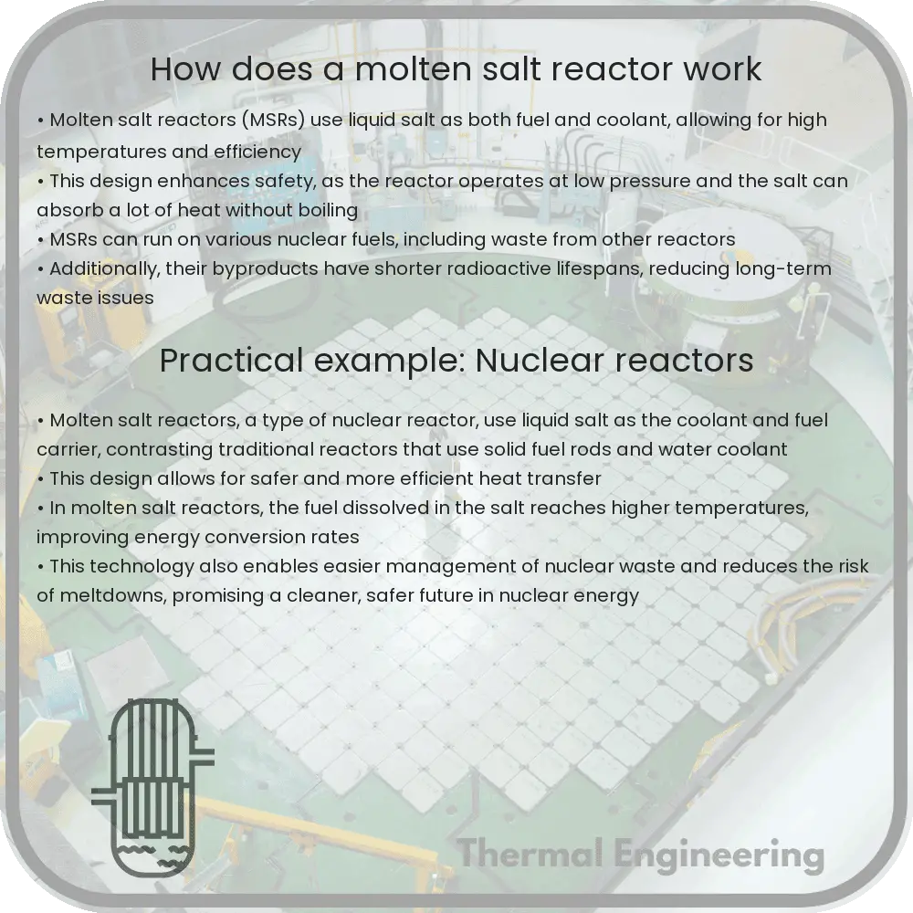
Molten salt reactors (MSRs) are a type of nuclear reactor where the primary coolant, or even the fuel itself, is a molten salt mixture. They offer several advantages over traditional nuclear reactors, such as higher thermal efficiencies and inherent safety features. Understanding how these reactors work is key to appreciating their potential in the future of energy production.

Core Components and Functionality

The basic operation of a molten salt reactor begins with its most central component: the liquid fuel. Unlike conventional reactors that use solid fuel rods, MSRs use fuel dissolved in molten salt. This fluid not only acts as the fuel but also serves as the coolant.

  • Reactor Core: The core of an MSR contains a mixture of molten fluoride or chloride salts. These salts can operate at high temperatures without turning into a gas and have excellent heat transfer properties.
  • Fuel Salt: The molten salt in the core typically contains fissile materials such as uranium-235 or thorium-232. The choice of salt and fuel depends on the reactor design and the specific application of the reactor.
  • Heat Exchanger: The hot molten salt is circulated through a heat exchanger where it transfers its heat to a secondary coolant. This heat can then be used to produce steam, driving turbines and generating electricity.
  • Pump Systems: To keep the molten salt circulating through the reactor core and the heat exchanger system, robust pumping systems are necessary due to the high temperatures and corrosive nature of the salts.

Neutron Moderation and Fuel Cycle

Neutron moderation is a critical aspect of controlling the nuclear fission process within any reactor. In molten salt reactors:

  • Moderator Materials: Materials like graphite or heavy water are often used to slow down the neutrons produced by fission. Slow neutrons are more likely to induce additional fission events, maintaining the nuclear chain reaction efficiently.
  • Thorium Fuel Cycle: Some MSRs are designed to utilize a thorium fuel cycle, where thorium-232 absorbs a neutron to become uranium-233, which is fissile. This cycle is particularly appealing because of thorium’s abundance relative to uranium.

Safety Features

Molten salt reactors are considered inherently safe for several reasons:

  1. Negative Temperature Coefficient: As the reactor heats up, the efficiency of the nuclear reaction decreases, automatically controlling the reactor’s power output and preventing overheating.
  2. Freeze Plug: A key safety feature in many MSRs is a freeze plug made of solidified salt. Located at the bottom of the reactor vessel, this plug will melt in the event of a critical failure, allowing the molten salt to drain from the core into a passive cooling tank below, effectively stopping the reaction.
  3. Chemical Stability: Unlike water, molten salts do not boil off or produce high pressures under the operating temperatures of an MSR, reducing the risk of a pressurized explosion.

Advantages Over Conventional Reactors

In comparison to traditional nuclear reactors, molten salt reactors offer several significant advantages:

  • Higher Operating Temperatures: This means they can achieve greater thermal efficiencies, potentially reaching up to 50% with advanced designs compared to about 33% for traditional water-cooled reactors.
  • Reduced Waste: MSRs can potentially reduce nuclear waste through more efficient fuel utilization and the capability to breed their own fuel.
  • Versatility: They can be designed for different applications, from large-scale power generation to small, modular setups ideal for remote areas or developing nations.

Molten salt reactors represent promising technology in nuclear power’s future, offering a combination of safety, efficiency, and sustainability. As research continues and technologies improve, MSRs could play a crucial role in meeting the world’s increasing energy demands while minimizing environmental impact.

Thermal insulation materials for pipelines

Learn about the different types of thermal insulation materials for pipelines, their properties, and applications.

Thermal insulation materials for pipelines

Understanding Thermal Insulation Materials for Pipelines

Thermal insulation is crucial in maintaining the efficiency and safety of pipeline systems used in various industries such as oil and gas, chemical, and heating & ventilation. Proper insulation helps in controlling the temperature of the fluids being transported, thereby ensuring optimal flow rates and preventing damage or accidents caused by extreme temperatures. This article explores the different types of thermal insulation materials used for pipelines and their respective properties and applications.

Types of Thermal Insulation Materials

There are several types of insulation materials that are commonly used for pipelines. Each type has unique characteristics that make it suitable for specific conditions and requirements.

  1. Fiberglass Insulation

Fiberglass is one of the most widely used insulation materials. It is made from fine fibers of glass and is available in blanket, board, or pipe forms. Fiberglass is prized for its high tensile strength, low thermal conductivity, and resistance to moisture and fire. It is suitable for both high and low temperature applications, typically ranging from -20°C to 650°C.

  1. Mineral Wool

Mineral wool can refer to either rock wool or slag wool and is made from inorganic fibers. Rock wool is produced from basalt or diabase, while slag wool is from steel mill slag. Mineral wool is excellent for thermal insulation, as well as for fire resistance and soundproofing. It is effective for temperatures up to 1000°C, making it ideal for high-temperature industrial applications.

  1. Polyurethane Foam

Polyurethane foam is a synthetic material known for its low thermal conductivity and good mechanical properties. It can be sprayed directly onto the pipeline or applied as pre-formed sheets. However, it is generally used in moderate temperature ranges from -200°C to 120°C and also offers good resistance to moisture intrusion.

  1. Calcium Silicate

Calcium silicate is often used for high-temperature pipelines in industrial applications. It has a high compressive strength and is structurally rigid, which makes it suitable for areas with high mechanical stresses. It effectively operates in temperatures up to 1200°C, offering both thermal insulation and fire protection.

  1. Ceramic Fiber

Ceramic fiber insulation is composed of alumina-silica fibers and is best known for its high temperature resistance, up to 1430°C. This material is often used for industrial furnace, kiln, and boiler applications where high temperature stability is crucial. Ceramic fiber is lightweight and can be manufactured in various forms including blankets, boards, and modules.

Choosing the Right Insulation Material

The choice of the right insulation material for a particular pipeline depends on several factors:

  • Temperature: The operating temperature of the pipeline is perhaps the most crucial factor. Materials must be able to withstand the maximum operating temperature without degrading.
  • Environmental Factors: Considerations such as moisture exposure, UV exposure, and chemical resistance should influence the choice of insulation material.
  • Mechanical Stresses: Some pipelines might be subject to vibrations or high external pressure, which requires mechanically strong materials like calcium silicate.
  • Cost and Efficiency: Finally, the cost of the material and its installation, as well as its thermal efficiency, will often dictate what is most practical for a given application.

By understanding the diverse range of pipeline insulation materials available and their specific properties, industries can make informed choices that enhance performance, economic efficiency, and safety standards.

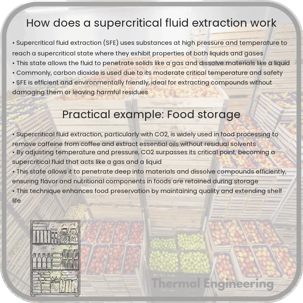
How does a supercritical fluid extraction work

Supercritical Fluid Extraction (SFE) is a high-efficiency, eco-friendly method used to separate substances using supercritical CO2 as a solvent.

How does a supercritical fluid extraction work

Understanding Supercritical Fluid Extraction

Supercritical Fluid Extraction (SFE) is a sophisticated extraction technique used primarily in the pharmaceutical, food, and environmental industries to separate one component (the extract) from another (the matrix) using supercritical fluids as the extracting solvent. The process is highly regarded for its efficiency and environmental friendliness, as it typically uses supercritical carbon dioxide (CO2) instead of chemical solvents.

What Are Supercritical Fluids?

Supercritical fluids are substances that are above their critical temperature and pressure, where they exhibit unique properties between liquids and gases. In this state, these fluids can penetrate materials like a gas but dissolve materials like a liquid. Supercritical CO2, which is the most commonly used supercritical fluid, has a critical point at approximately 31.1°C (88°F) and 73.8 bar (1071 psi).

How Does Supercritical Fluid Extraction Work?

The process of Supercritical Fluid Extraction can be summarized in the following steps:

  1. Increasing Pressure and Temperature: CO2 is pressurized and heated until it reaches supercritical conditions, meaning it is heated and pressurized beyond its critical point.
  2. Solubilization: The supercritical CO2 passes through the raw material, acting as a solvent to dissolve the extractable substances.
  3. Separation: Once the supercritical CO2 dissolves the target compounds, the mixture is then passed into a separator at a lower pressure, leading to the precipitation of the extracted substances, while the CO2 returns to a gaseous state and is recycled or released.
  4. Collection: The extracted substances are collected and the CO2 can be recycled back into the system for further extractions.

Advantages of Using Supercritical CO2 as a Solvent

  • Non-Toxicity: CO2 is non-toxic, making SFE a safer alternative to other methods that use hazardous chemicals.
  • Efficiency: The solvent power and the diffusivity of supercritical CO2 can be adjusted by changing the temperature and pressure, making the process highly efficient.
  • Low Temperature Processing: Since the critical temperature of CO2 is relatively low, SFE can be used for extracting heat-sensitive compounds without damaging them.
  • Environmental Friendliness: CO2 is recycled in the system, leading to minimal environmental waste and emissions.

Applications of Supercritical Fluid Extraction

Supercritical Fluid Extraction is particularly advantageous in industries where purity and efficiency are paramount. Some of the common applications include:

  • Decaffeination of Coffee and Tea: SFE is used to remove caffeine from coffee beans and tea leaves without affecting the flavor.
  • Extraction of Flavors and Fragrances: Essential oils and other aroma compounds are often extracted from plants using SFE for use in perfumes and food products.
  • Pharmaceuticals: SFE is used for the extraction of active ingredients from plants and other organic sources for pharmaceutical applications.
  • Environmental Remediation: SFE is effective for cleaning up contaminated soils and extracting harmful compounds.

Supercritical Fluid Extraction represents a fascinating combination of basic physics principles with advanced engineering practices. Its ability to efficiently extract components without the use of harmful chemicals showcases a significant step forward in both industrial processing and environmental stewardship.

How does a vapor-compression refrigeration cycle work

Learn about the vapor-compression refrigeration cycle, the most commonly used method in refrigerators and air conditioners for effective heat transfer.

How does a vapor-compression refrigeration cycle work

Understanding the Vapor-Compression Refrigeration Cycle

The vapor-compression refrigeration cycle is the most common method used in refrigerators, air conditioners, and heat pumps to transfer heat from one area to another. This process is vital for achieving controlled cooling and heating in various applications. Here, we will walkthrough the basic components and steps involved in a vapor-compression refrigeration cycle.

Key Components of the Cycle

  • Evaporator: Absorbs heat from the environment or space to be cooled.
  • Compressor: Pumps the refrigerant, raising its pressure and temperature.
  • Condenser: Releases the absorbed heat to the outside environment.
  • Expansion Valve: Lowers the pressure of the refrigerant, allowing it to expand and cool.

Steps in the Vapor-Compression Cycle

  1. Evaporation: The cycle begins in the evaporator, where the low-pressure liquid refrigerant absorbs heat from the surroundings. This heat converts the liquid into a gas.
  2. Compression: The refrigerant vapor is then compressed by the compressor. As the gas is compressed, its pressure and temperature both rise significantly. The refrigerant becomes a high-pressure hot vapor.
  3. Condensation: Next, this high-pressure hot vapor travels to the condenser. Here it releases its heat to the outside environment, condensing into a high-pressure liquid.
  4. Expansion: The high-pressure liquid then passes through the expansion valve, which reduces its pressure. This sudden reduction in pressure cools the liquid substantially, turning part of it into a low-pressure mixture of liquid and vapor, ready to absorb heat in the evaporator again.

Thermodynamics of the Cycle

The efficiency and effectiveness of the vapor-compression cycle depend largely on the principles of thermodynamics, particularly those relating to pressure, temperature, and phase changes of the refrigerant.

As the refrigerant undergoes these changes, it follows principles described by the First Law of Thermodynamics (conservation of energy) and the Second Law of Thermodynamics (increased entropy in heat transfer processes). The cycle is designed to optimize the boiling and condensation points of the refrigerant, exploiting its latent heat properties at various stages.

Equations concerning the energy input to the compressor (in terms of work done) and heat exchanged in the evaporator and condenser are crucial for understanding the energy dynamics within the cycle:

  • Work done by compressor (W): W = m * (h2 – h1)
  • Heat absorbed in evaporator (Qin): Qin = m * (h1 – h4)
  • Heat rejected in condenser (Qout): Qout = m * (h2 – h3)

Here, m represents the mass flow rate of the refrigerant, and h denotes the specific enthalpy at various points in the cycle.

Applications and Importance

The vapor-compression cycle is fundamental in many modern technologies that require cooling and heating. It is essential for achieving desired temperature conditions in homes, offices, refrigerators, and industrial processes, demonstrating its vast importance in everyday life and various industrial applications.

Understanding this cycle not only helps in designing more efficient heating and cooling systems but also is crucial for advancing technologies that depend on precise temperature control, such as data center cooling and process manufacturing.

Conclusion

The vapor-compression refrigeration cycle demonstrates a classic example of applied thermodynamics in a practical, everyday system. By manipulating the pressure and temperature of a refrigerant, engineers can effectively control the heating and cooling in various devices, making this cycle a cornerstone of modern refrigeration and air conditioning technology.

How does a magnetic refrigeration system cool

Learn about magnetic refrigeration, a green cooling technology driven by the magneto-caloric effect and magnetocaloric materials.

How does a magnetic refrigeration system cool

Understanding Magnetic Refrigeration: A Cool Technology Based on Magnets

Magnetic refrigeration is an innovative cooling technology that operates on the magneto-caloric effect (MCE). Unlike traditional gas-compression refrigerators, which use refrigerant gases and compressors, magnetic refrigeration relies on a magnetic field and special materials, making it potentially more energy efficient and environmentally friendly. This article explores how magnetic refrigeration systems function and their potential benefits.

What is the Magneto-Caloric Effect?

The magneto-caloric effect is the principle behind magnetic refrigeration. It refers to the temperature change that magnetocaloric materials undergo when exposed to a changing magnetic field. When a magnetic field is applied to certain materials, such as gadolinium or iron rhodium, their temperature increases. Conversely, when the magnetic field is removed, the material cools down. This phenomenon is reversible and can be used to transfer heat in a cooling cycle.

Components of a Magnetic Refrigeration System

  • Magnetocaloric Material: The core component of the system, often made from alloys like gadolinium or iron rhodium, that changes temperature in response to a magnetic field.
  • Magnets: Permanent magnets or electromagnets used to alter the magnetic field around the magnetocaloric material. The strength and cycling of the magnetic field are crucial for the efficiency of the system.
  • Heat Exchange Mechanism: A system that helps in transferring heat to and from the magnetocaloric material. This can be a fluid that flows past the material, absorbing and dissipating heat.
  • Control System: Used to control the timing and strength of the magnetic field, as well as the flow of the heat transfer fluid.

How Does Magnetic Refrigeration Work?

  1. Magnetization: The magnetocaloric material is placed within a magnetic field, causing it to heat up. This is due to the alignment of magnetic moments inside the material, which reduces its magnetic entropy and increases its temperature.
  2. Heat Removal: The heated material transfers its excess heat to a fluid or air in a heat exchanger. This step is crucial as it captures the heat for removal, similar to how a conventional refrigerator operates.
  3. Demagnetization: The magnetic field is removed from the magnetocaloric material, causing it to cool below its original temperature. The decrease in temperature comes from the increase in magnetic entropy, which absorbs thermal energy from the surrounding environment.
  4. Heat Absorption: In the final step, the now cooler material absorbs heat from the refrigerator’s interior. This process lowers the temperature inside the refrigeration compartment, effectively cooling the stored contents.

Advantages of Magnetic Refrigeration

Magnetic refrigeration offers several advantages over traditional cooling methods:

  • Environmental Impact: No harmful refrigerants are used, which reduces the potential for ozone depletion and global warming potential.
  • Energy Efficiency: Potentially more energy-efficient due to fewer mechanical parts and the reversible nature of the cooling cycle.
  • Noise and Maintenance: Quieter operation and possibly lower maintenance costs, as there are no compressors or moving refrigerant.

Challenges and Future Outlook

Despite its potential, magnetic refrigeration is not yet widely adopted in commercial applications due to several challenges. These include cost and availability of magnetocaloric materials, scalability of the technology, and the need for strong, efficient magnets. However, ongoing research and development are aimed at overcoming these obstacles, suggesting a cooler, greener future powered by magnetic refrigeration technology.

As magnetic refrigeration continues to develop, it could prove to be a key player in energy-efficient, environmentally friendly cooling technology, providing a viable alternative to conventional refrigeration methods, particularly in contexts where the environmental impact and energy consumption are critical considerations.

How does an ultrasonic humidifier generate mist

Learn how ultrasonic humidifiers use high-frequency vibrations to efficiently create mist and increase room humidity without heat.

How does an ultrasonic humidifier generate mist

Understanding Ultrasonic Humidifiers: How They Generate Mist

An ultrasonic humidifier is a type of device used to increase the humidity (moisture level) in the air of a room or building. Unlike traditional humidifiers that boil water to produce steam, ultrasonic humidifiers use a different, more energy-efficient mechanism to create a fine mist. The core of this technology involves ultrasonic vibration.

Key Components of an Ultrasonic Humidifier

The main components of an ultrasonic humidifier include:

  • Water reservoir
  • Metal or ceramic diaphragm (vibrating element)
  • Oscillator
  • Fan

The Role of Ultrasonic Vibrations

At the heart of the ultrasonic humidifier’s operation is the diaphragm, which vibrates at an ultrasonic frequency. An oscillator connected to this diaphragm produces these high-frequency vibrations, typically in the range of 1 to 5 MHz. When the diaphragm vibrates, it does so at such a fast pace that it cannot be seen by the naked eye.

As the ultrasonic waves travel, they transmit energy to the water present in the unit’s reservoir. This energy agitates the water, causing it to leave the surface in the form of tiny water droplets, creating a visible mist.

Process of Mist Creation and Release

The process of converting water into mist using ultrasonic vibrations involves several steps:

  1. The diaphragm moves down, pushing against the water in the reservoir.
  2. This downward motion creates a vacuum above the diaphragm as it quickly moves back up.
  3. The vacuum action draws water up from the reservoir into the area above the diaphragm.
  4. As the diaphragm rapidly moves up and down, it strikes the water surface at a high frequency, splitting the water into fine droplets that form a dense fog or mist.
  5. This mist is then pushed out into the air by the fan, increasing the moisture level of the surrounding environment.

Benefits and Considerations

Ultrasonic humidifiers are favored for several reasons:

  • Energy Efficiency: They use considerably less electricity compared to warm mist humidifiers, as there’s no need to heat the water.
  • Silent Operation: The high-frequency vibrations are typically beyond human hearing, making these devices exceptionally quiet.
  • Fine Mist: The water droplets are extremely small, ensuring they can be easily absorbed into the air without leaving damp spots on surfaces.

However, users should be mindful of the type of water used in ultrasonic humidifiers. Using unfiltered tap water can lead to the dispersion of minerals and other impurities into the air, which might result in white dust forming on surfaces and potential respiratory concerns. It is generally recommended to use distilled or demineralized water to mitigate these issues.

Conclusion

The science behind ultrasonic humidifiers showcases a clever application of ultrasonic technology to address everyday needs. By generating fast vibrations that create mist, these devices provide an efficient and quiet method for humidifying the air, underlining both the ongoing relevance and adaptability of ultrasonic technology in practical applications.

How does an electromagnetic pump move liquid metal

Learn about electromagnetic pumps and their crucial role in transporting liquid metals in high-temperature industries like nuclear reactors and spacecraft cooling systems.

How does an electromagnetic pump move liquid metal

Understanding Electromagnetic Pumps in Liquid Metal Transportation

Electromagnetic pumps are devices that play a critical role in the movement of liquid metals, particularly in industries where metals need to be transported at extremely high temperatures, such as in nuclear reactors or the cooling systems of spacecraft. These pumps use magnetic fields instead of moving mechanical parts, making them ideal for handling molten metals that can be highly corrosive and damaging to conventional pumps.

Principles of Operation

The operational principle of an electromagnetic pump is based on Lorentz force, which is the force exerted by a magnetic field on a moving charge. In the case of electromagnetic pumps, the moving charge is the electrically conductive liquid metal. The Lorentz force can be described by the following equation:

\[ F = q(E + v \times B) \]

  • F represents the Lorentz force
  • q is the charge
  • E stands for electric field
  • v is the velocity vector of the charge
  • B denotes the magnetic field

However, in the context of electromagnetic pumps, this translates into the interaction between the induced magnetic field and the current generated from the flow of the metallic liquid, which in turn creates a force that moves the metal along the pump.

Types of Electromagnetic Pumps

There are primarily two types of electromagnetic pumps used for transporting liquid metal:

  1. Conduction Pumps: They are simpler in design and are used for low flow rate applications. In a conduction pump, an electric current is passed directly through the liquid metal (which acts as the conductor), and a perpendicular magnetic field is applied. The interaction between the current and magnetic field generates the force needed to drive the liquid metal through the pump.
  2. Induction Pumps: These are more suitable for high flow rate applications. Induction pumps use an alternating magnetic field to induce currents in the liquid metal. This type of pump typically includes a series of electromagnets around a conducting pipe where the liquid metal flows. The alternating magnetic field induces a current loop in the liquid which interacts back with the magnetic field to produce a force that propels the liquid forward.

Applications and Advantages

Electromagnetic pumps are widely used in various industrial applications, including:

  • Nuclear Reactors: These pumps circulate molten lead or sodium within reactors, as they can operate at the high temperatures encountered in such environments without degradation.
  • Solar Thermal Power Plants: For transporting molten salts that store and transfer solar energy.
  • Steel and Aluminium Production: To handle molten metals safely and efficiently.

The main advantages of using electromagnetic pumps include:

  • No Moving Mechanical Parts: Reduces maintenance needs and improves reliability.
  • Ability to Operate at High Temperatures: Makes them suitable for applications involving molten materials.
  • High Efficiency: These pumps can be very efficient, with efficiencies of up to 85% not being uncommon.
  • Chemical Inertness: As the construction materials can be chosen to be non-reactive with the liquid metal.

Understanding the physics behind electromagnetic pumps is vital for engineering professionals involved in industries where liquid metals need to be transported safely and efficiently. They embody an excellent integration of electromagnetism with fluid dynamics, showcasing how fundamental physics principles can be applied to solve complex engineering challenges.

How does a ram pump lift water

Learn how a hydraulic ram pump lifts water to higher elevations using the kinetic energy of falling water, ideal for remote locations.

How does a ram pump lift water

Understanding the Functioning of a Hydraulic Ram Pump

A hydraulic ram pump is an intriguing piece of engineering that has the ability to lift water to higher elevations without requiring any external source of power except for the kinetic energy of falling water. These pumps use the fundamental principles of water dynamics and an ingeniously simple mechanism to elevate water, making them especially useful in rural or remote locations where electricity or fuel-powered pumps are not feasible.

How Does a Ram Pump Work?

The key components of a hydraulic ram pump include the following:

  • Inlet pipe (drive pipe)
  • Impulse valve (waste valve)
  • Delivery valve (check valve)
  • Pressure chamber (air vessel)
  • Delivery pipe

The operation of a ram pump involves four main stages: filling, impulsion, delivery, and recovery.

  1. Filling: Water flows from a higher elevation through the inlet pipe, gaining speed and kinetic energy as it descends. This fast moving water enters the pump through the impulse valve.
  2. Impulsion: When sufficient water velocity is achieved, the impulse valve suddenly closes, causing water hammer—a sharp rise in pressure due to the inertia of the water in the drive pipe.
  3. Delivery: The increased pressure opens the delivery valve, allowing water to flow into the pressure chamber. This chamber contains air that gets compressed by the incoming water, thus storing energy. The compressed air acts like a spring, pushing water into the delivery pipe toward an elevated storage or usage area.
  4. Recovery: As the pressure drops, the impulse valve reopens, allowing the process to start over as more water flows into the pump.

Energy and Efficiency Considerations

The efficiency of ram pumps is largely dependent on the height difference between the water source and the pump versus the height to which the water is elevated. Generally, the greater the fall of water into the pump, the higher it can be lifted, but with diminishing efficiency. A practical rule of thumb is that for every foot of fall into the pump, the water can be lifted approximately ten feet. However, the actual lifting capacity and efficiency can be influenced by factors such as the length and diameter of the inlet and outlet pipes, as well as the size and configuration of the pump itself.

Hydraulic ram pumps operate without electricity or fuel. Once started, they can continue to operate unattended for extended periods, requiring minimal maintenance. This makes them not only economically viable but also environmentally friendly.

Applications and Use Cases

Due to their simplicity and sustainability, hydraulic ram pumps are extensively used in agricultural and rural development projects. They are ideal for irrigation, livestock watering, and rural water supply where the source is a stream or river with sufficient flow and a modest fall.

Understanding and harnessing the principles of physics in devices like the hydraulic ram pump showcases how simple yet effective solutions can greatly benefit various communities, particularly in less-developed and remote areas.

How does a thermoelectric cooler work

Learn how thermoelectric coolers utilize the Peltier effect for efficient, solid-state cooling in compact and precise temperature control applications.

How does a thermoelectric cooler work

Understanding How a Thermoelectric Cooler Works

A thermoelectric cooler (TEC), also known as a Peltier cooler, is a solid-state device that provides cooling through the Peltier effect. Unlike conventional refrigerators that use vapor compression or absorption cycles, TECs are popular for their compact size, lack of moving parts, and ability to precisely control temperatures. Here, we’ll explore the fundamental principles behind thermoelectric cooling, its components, and its practical applications.

The Basic Principle: The Peltier Effect

The Peltier effect is the underlying principle of thermoelectric cooling. It occurs when an electric current flows through two dissimilar conductors or semiconductors (types N and P), which are joined at two junctions. The current drives a transfer of heat from one junction to the other, creating a cold junction and a hot junction.

When a DC current is applied to the thermoelectric module, electrons and holes at the junction of these two materials either absorb heat or release heat depending on the direction of current flow. If the current is reversed, the hot and cold sides also reverse.

Components of a Thermoelectric Cooler

A typical thermoelectric cooler consists of the following key components:

  • Thermoelectric Modules: These are the core of the cooler, usually made from bismuth telluride (Bi2Te3). Each module includes many pairs of n-type and p-type semiconductors sandwiched between two ceramic plates that provide mechanical strength and electrical insulation.
  • Heat Sink: This component is responsible for dissipating the heat transferred from the cold side to the hot side of the module, usually to the ambient air.
  • Fan: Often used in conjunction with the heat sink to increase the heat dissipation rate via forced convection.
  • Power Supply: Provides and controls the DC current required for the operation of the TEC.

How It Works

To initiate cooling, a DC current is passed through the thermoelectric module. This current forces a heat transfer from one side of the semiconductor pairs to the other side, consequently chilling the opposite side. The cold side absorbs heat from the environment or an object that needs to be cooled, like food in a portable cooler. Meanwhile, the extracted heat is carried to the hot side of the module, from where the heat sink and fan disperse it into the surrounding environment.

Applications of Thermoelectric Coolers

  • Consumer Electronics: Used in refrigeration of small personal devices and compact coolers.
  • Medical Applications: Used for controlled cooling of samples and maintaining constant temperatures in medical equipment.
  • Automotive: Provides cooling for car seats or for temperature regulation in batteries.
  • Computers: Applied in cooling CPUs and other critical components in computers and servers to maintain optimal operating temperatures.

Advantages and Limitations

Thermoelectric coolers offer several advantages: they are lightweight, have no moving mechanical parts (reducing maintenance), are environmentally friendly (as they do not use chemical refrigerants), and can achieve rapid cooling. However, their efficiency is generally lower than traditional cooling methods, especially for large-scale applications, and they can be subject to overheating if not properly managed.

Conclusion

Thermoelectric coolers provide a versatile and reliable cooling solution for a range of applications where conventional refrigeration is unfeasible or too bulky. Understanding its working principle not only sheds light on a fascinating area of thermal physics but also opens up possibilities for innovative cooling solutions across different sectors of technology and medicine.

How does an oil refinery process crude oil

Learn about oil refineries and their crucial role in transforming crude oil into gasoline, diesel, and other petroleum products.

How does an oil refinery process crude oil

Understanding the Process of an Oil Refinery

Oil refineries are complex engineering facilities that are crucial to the production of gasoline, diesel fuel, and other petroleum products from crude oil. Crude oil itself is a mixture of hydrocarbons, and the goal of an oil refinery is to separate this mixture into its useful components and remove unwanted impurities.

Key Processes in an Oil Refinery

Refining crude oil involves several key processes:

  • Distillation: This is the first and most fundamental process in an oil refinery. Crude oil is heated in a large furnace to temperatures where different hydrocarbon compounds boil off and can be separated based on their boiling points. The resulting vapors ascend a distillation column, where they cool and condense back into liquids at different levels, effectively separating the crude oil into various ‘fractions’ or types of fuel.
  • Conversion Processes: These processes alter the chemical structures of the fractions. Techniques such as ‘cracking’ break larger molecules into smaller ones, while ‘reforming’ rearranges molecular structures. Cracking can be thermal (using heat) or catalytic (using a catalyst).
  • Treatment: This involves removing impurities such as sulfur, nitrogen, and metals that can affect the quality of the final products. Processes include hydrotreating, which uses hydrogen to clean up the refinery products.
  • Blending: The final step in the refinery process involves blending different refined products to achieve specific properties and standards required for commercial fuels and other products.

Distillation Process

At the heart of an oil refinery is the distillation unit, often called the crude unit. It operates on the principle of fractional distillation. A typical column might consist of several trays or plates, each collecting different hydrocarbon fractions as they condense at different temperatures:

  1. Light distillates such as LPG (liquefied petroleum gas), gasoline, and naphtha condense at the top where the temperature is the lowest.
  2. Medium distillates including kerosene and diesel collect in the middle sections of the column.
  3. Heavy distillates and residues such as fuel oil and bitumen settle at the bottom of the column due to their high boiling points.

Conversion and Treatment

Conversion processes are critical for producing more valuable and in-demand products like gasoline. Catalytic cracking, for example, uses a catalyst to aid in breaking long-chain hydrocarbons into shorter, more valuable chains. Catalytic reforming, on the other hand, uses a catalyst to rearrange or combine molecules to improve the quality of the fuel.

Treatment processes are critical to meet environmental regulations and fuel standards, ensuring that products are safe for consumption and use. Hydrotreating is a prominent treatment process where hydrogen gas is bubbled through the petroleum product to remove contaminants like sulfur, converting them into hydrogen sulfide which can then be removed.

Blending and Storage

The final products of the refinery processes often require precise blending to meet specific standards. For instance, different additives might be blended into gasoline to inhibit corrosion, improve combustion, and reduce emissions. Once blended, the final products are stored in large tanks and eventually transported to consumers.

Oil refining is a dynamic and essential field in engineering. It combines complex chemical engineering processes with real-world economics and environmental considerations, showcasing the vital role of engineers in transforming natural resources into valuable commodities.