Facebook Instagram Youtube Twitter

Archimedes Screw Pump | Ancient & Modern Water Lifting

Explore the enduring utility of the Archimedes screw pump, from ancient irrigation to modern engineering applications.

Archimedes Screw Pump | Ancient & Modern Water Lifting

Archimedes Screw Pump: Bridging Ancient Ingenuity and Modern Engineering

The Archimedes screw pump is a machine historically credited to Archimedes of Syracuse, one of the leading scientists and mathematicians of the ancient world. Although there is some debate regarding its actual origin, this device has been effectively utilized since its inception to lift water to higher elevations. Today, it continues to see diverse applications, from irrigation systems to wastewater management facilities, combining ancient principles with modern engineering needs.

Historical Overview

The Archimedes screw, believed to have been developed in the 3rd century BCE, was originally used to irrigate the fertile gardens of Babylon and the croplands of ancient Egypt. The device comprises a screw (a helical surface surrounding a central cylindrical shaft) housed inside a hollow tube. As the screw is turned, usually by manual labor or by harnessing the power of animals, water is scooped up from a lower point and expelled at a higher elevation, following the helical path.

Principle of Operation

The principle behind the Archimedes screw pump is relatively straightforward. When the bottom end of the tube dips into a body of water and the apparatus is rotated, water is trapped between the threads of the screw and lifted as the screw turns. The elevation to which water can be lifted corresponds to the length of the screw and the angle of inclination. The efficiency of an Archimedes screw pump is influenced by several factors including the screw’s diameter, pitch (the distance between each thread on the screw), and the speed of rotation.

Modern Applications

In modern times, the Archimedes screw is utilized not only for lifting water but also for a variety of other applications, such as in wastewater treatment plants and in the production of hydroelectric power. Some notable modern uses include:

  • Flood control and stormwater pumping
  • Agricultural irrigation
  • Wastewater treatment facilities, where they help in moving solids and slurries
  • Hydropower generation, enabling low ecological impact compared to traditional turbines

Benefits of the Archimedes Screw Pump

One of the reasons the Archimedes screw pump is still widely used today is its numerous advantages over other types of pumps. These include:

  • High efficiency with capability to move large volumes of water
  • Robustness and simplicity in design leading to lower maintenance costs
  • Capability to handle water with high levels of silt and debris without clogging
  • Environmental friendliness, especially when used for hydropower

Challenges and Limitations

Despite its numerous advantages, the Archimedes screw pump does have some limitations. The main challenges include:

  • Relatively low lift capability, making it unsuitable for applications requiring high head pressures
  • The need for precise alignment to ensure efficiency and prevent rapid wear
  • Potential for water leakage back down the screw if not properly maintained

In conclusion, the Archimedes screw pump is a brilliant example of how ancient technology can be adapted to meet modern engineering needs. Its continued use in various fields underscores its reliability and efficiency, bridging a gap between the past and present engineering solutions. Whether in the fields of agriculture, waste management, or renewable energy, the Archimedes screw is a testament to the enduring legacy of ancient innovation in contemporary applications.
Tidal Stream Turbine | Sustainable Marine Energy

Learn how tidal stream turbines harness the kinetic energy of tidal currents to generate sustainable, renewable marine energy.

Tidal Stream Turbine | Sustainable Marine Energy

Understanding Tidal Stream Turbines: Pioneers of Sustainable Marine Energy

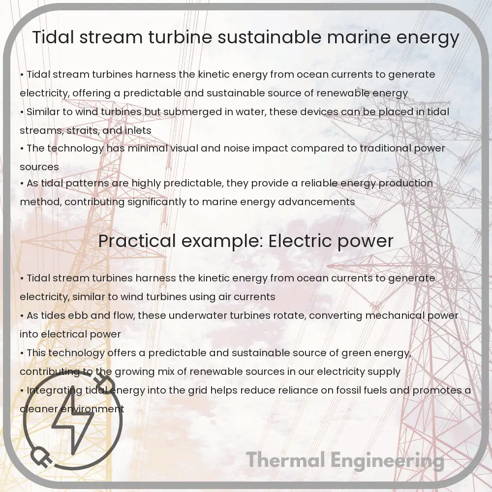
Tidal stream turbines are an innovative form of renewable energy technology that harnesses the kinetic energy of tidal currents. Much like wind turbines convert wind energy into electricity, tidal stream turbines convert the energy of moving water. Positioned in waterways with high tidal movement, these turbines represent a promising sustainable energy solution with minimal environmental impact.

How Tidal Stream Turbines Work

The core principle behind tidal stream turbines is the conversion of the kinetic energy from fast-moving volumes of water into electrical energy. As tides ebb and flow, large volumes of water move swiftly in and out of coastal areas. Turbines placed in these streams capture this kinetic energy through their rotor blades, which start to turn as water passes over them. This rotational motion then drives a connected generator to produce electricity.

The efficiency of a tidal stream turbine can be described by the equation:

\[ P = \frac{1}{2} \rho A v^3 C_p \]

Where:

  • \(\rho\) (rho) is the water density,
  • \(A\) (uppercase A) is the rotor area,
  • \(v\) (v) is the velocity of the water stream,
  • \(C_p\) (C sub p – Power Coefficient) measures the turbine’s efficiency in converting the energy from the water flow into electricity. It is a value between 0 and 1, where 1 would signify 100% conversion efficiency, which is theoretically not achievable due to various losses.

Types of Tidal Stream Turbines

  • Horizontal Axis Turbines: These turbines have their rotor shaft arranged horizontally and parallel to the water flow, akin to traditional wind turbines. Most tidal stream turbines are of this type because they typically generate greater amounts of power and are more efficient in aligned water flows.
  • Vertical Axis Turbines: These have a vertical shaft and can capture tidal currents from any direction, making them versatile in fluctuating tidal conditions. However, they generally have lower efficiency rates compared to horizontal turbines.

Advantages of Tidal Stream Turbines

  • Renewability: Tidal energy is completely renewable as it is governed by gravitational forces among the Earth, moon, and sun, which are predictable and essentially infinite from a human perspective.
  • Low Environmental Impact: Unlike fossil fuels, tidal stream turbines produce no greenhouse gases or other pollutants. Their installation is designed to have minimal impact on the surrounding marine environment.
  • Predictability: Tidal currents are highly predictable compared to wind and solar sources, allowing better planning of power generation.
  • High Energy Density: Water is approximately 800 times denser than air, which means that even slow-moving tidal currents can generate significant amounts of energy.

Challenges and Considerations

Despite their benefits, the deployment of tidal stream turbines faces several challenges. These include:

  • High Initial Costs: The installation and maintenance of tidal turbines can be expensive due to the harsh marine environment and the nascent technology.
  • Environmental Concerns: There are concerns about potential impacts on marine life and habitats. Extensive environmental assessments are conducted before installations.
  • Location Limitations: Effective deployment of these turbines requires sites with strong tidal streams, which may not be available near areas with high energy demand.

In conclusion, tidal stream turbines represent a significant step forward in sustainable marine energy. As technology progresses and costs decrease, they have the potential to play a vital role in our global renewable energy portfolio, contributing to reduced carbon emissions and cleaner, more sustainable energy systems.

Lobe Pump | Gentle Handling in Food & Pharma

Learn about lobe pumps, their design, operation, and key applications in food and pharmaceutical industries.

Lobe Pump | Gentle Handling in Food & Pharma

Understanding Lobe Pumps: Their Application in Food and Pharmaceutical Industries

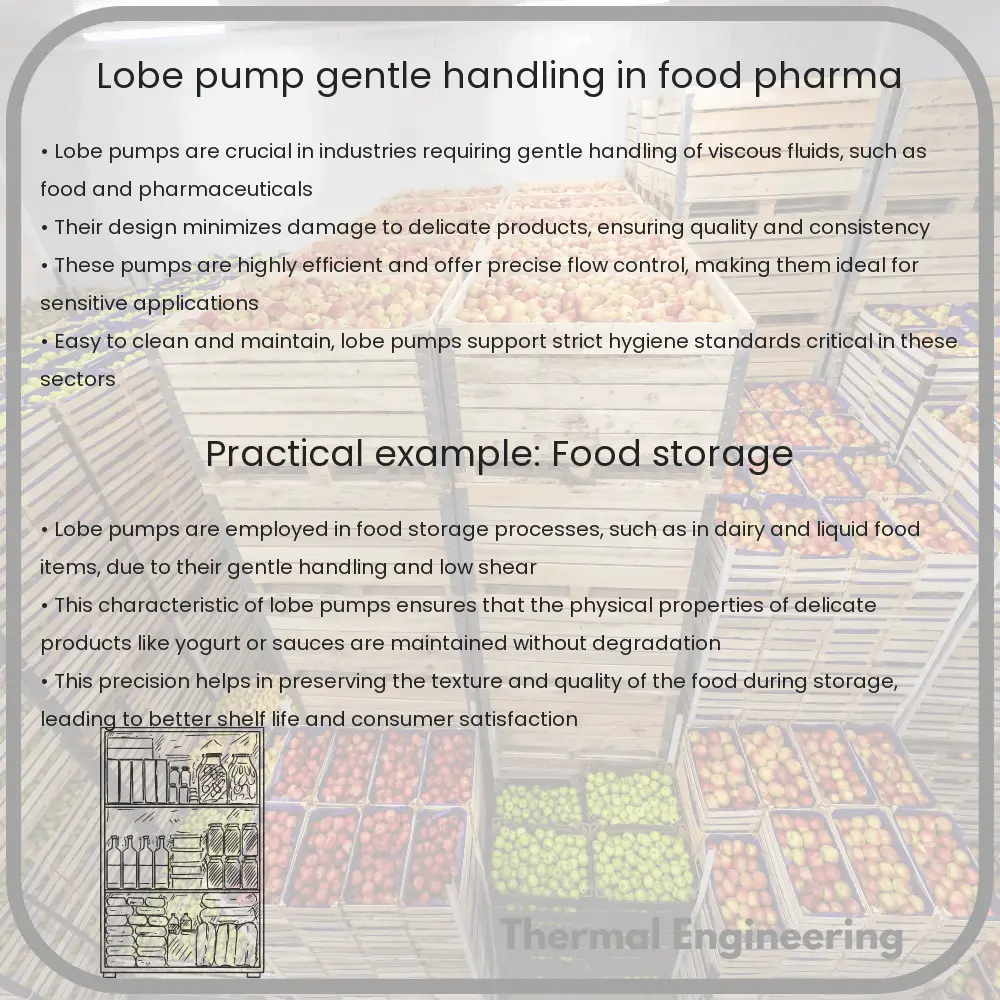
Lobe pumps are a type of positive displacement pump used extensively in various industries, especially in food processing and pharmaceuticals. These pumps are highly valued for their ability to handle fluids gently which is crucial for maintaining the integrity and quality of delicate products.

Principle of Operation

Lobe pumps operate on a simple principle: two synchronized, rotating lobes create a vacuum at the pump inlet which draws in the fluid. These lobes rotate without touching each other, driven by external timing gears located in the gearbox. As the lobes rotate, the captured fluid is transported around the inner periphery of the casing from the inlet side to the outlet side. Finally, the fluid is forced out of the pump under pressure created by the meshing of the lobes.

Components of a Lobe Pump

  • Lobes: Usually made of stainless steel or other high-quality metals, the lobes are the crucial components that move the fluid. They are designed in various shapes like bi-wing, tri-lobe, or multi-lobe configurations.
  • Gearbox: Houses the gears required to drive the lobes synchronously, ensuring they do not touch each other.
  • Sealing system: Seals prevent leakage of the fluid from the pump, maintaining efficiency and hygiene. Options range from simple lip seals to more complex mechanical and magnetic seals depending on the level of containment required.
  • Housing: Encases the internal components and is usually constructed from high-grade materials that withstand the hygienic and cleaning standards of the food and pharmaceutical industries.

Advantages of Lobe Pumps in Sensitive Industries

  1. Gentle Handling: The non-contact nature of the lobe operation minimizes shear and agitation, making it ideal for handling shear-sensitive products like yogurts or biopharmaceuticals.
  2. Hygienic Design: Lobe pumps can be easily cleaned and sterilized, adhering to strict sanitary standards essential in food processing and pharmaceutical manufacturing.
  3. Versatility: Capable of handling a wide range of viscosities, from water-like fluids to highly viscous pastes.
  4. Low Maintenance: With fewer parts that are susceptible to wear and tear, lobe pumps typically have lower maintenance costs than other types of pumps.

Applications within the Industries

In the food industry, lobe pumps are used for transferring a variety of products including sauces, dairy items, and confectionery items. Their gentle pumping action is crucial for maintaining the quality and texture of foods that are sensitive to shear forces.

In the pharmaceutical industry, these pumps facilitate the processing of lotions, gels, and ointments. They are also essential during the manufacturing of APIs (Active Pharmaceutical Ingredients), where contamination-free and precise dosing is crucial.

Challenges and Precautions

While lobe pumps offer considerable advantages, they also face certain challenges such as dealing with abrasive wear when handling grainy or particulate-laden fluids. Moreover, the initial cost can be higher than other pump types, though often justified by lower maintenance costs and superior performance in critical applications.

Selecting the right lobe pump—with appropriate lobe design, material, and sealing system—is crucial for operational efficiency and longevity. Regular maintenance and monitoring are also vital to ensure optimal performance and to prevent unexpected downtimes in crucial processes.

Through their gentle handling, hygiene, and efficiency, lobe pumps continue to be indispensable in the food and pharmaceutical industries, reflecting their adaptability and crucial role in modern manufacturing and processing operations.

Thermal management in electronics

Learn about thermal management in electronics, a critical engineering field that ensures devices operate efficiently without overheating.

Thermal management in electronics

Understanding Thermal Management in Electronics

Thermal management in electronics is a critical area of engineering that focuses on managing the heat produced by electronic components. The primary goal is to maintain optimal temperatures to prevent overheating, ensure efficient function, and extend the lifespan of electronic devices.

Why is Thermal Management Important?

Electronic devices generate heat as a byproduct of electrical energy. Excessive heat can lead to thermal stress, reduced reliability, and failures in electronic components. It can also affect the performance and stability of the device. Therefore, efficient thermal management systems are crucial for maintaining performance standards and preventing damage due to overheating.

Basic Principles of Heat Transfer

Heat transfer in electronics can be understood through three primary mechanisms:

  • Conduction: Transfer of heat through materials. In electronics, this often occurs within the component or between the component and the heat sink.
  • Convection: Transfer of heat through a fluid medium, such as air or a cooling liquid, which is often enhanced by fans or pumps.
  • Radiation: Transfer of heat through electromagnetic waves, which generally plays a lesser role in small scale electronic devices but can be significant in larger systems or specific contexts.

Components of Thermal Management Systems

Effective thermal management in electronics utilizes several components and strategies:

  • Heat Sinks: These are physical components made of materials with high thermal conductivity, such as aluminum or copper. They are designed to disperse heat from hotter areas (like a CPU) to cooler areas by increasing the surface area in contact with air.
  • Thermal Compounds: Also known as thermal grease, these enhance the efficiency of heat transfer between the component and the heat sink.
  • Cooling Fans: Often used in conjunction with heat sinks, fans promote air circulation to increase heat dissipation.
  • Heat Pipes: Vacuum-sealed pipes containing a small amount of liquid, which vaporizes at the hot interface, absorbing heat, and condenses back to a liquid at the cold interface, releasing the absorbed heat.
  • Liquid Cooling Systems: These systems use a coolant fluid that circulates through a pump, absorbing heat from the components and transferring it to a radiator, where it is dissipated into the environment.

Thermal Modeling and Computational Techniques

To design and optimize these thermal management systems, engineers use various computational techniques and modeling tools. Finite Element Analysis (FEA) and Computational Fluid Dynamics (CFD) are prominent methods used to simulate heat transfer and flow dynamics within electronic systems. These tools help predict thermal behavior and guide the design of more effective cooling systems.

Future Trends

As electronic devices continue to shrink in size while increasing in performance, managing heat effectively becomes more challenging and crucial. Innovations in material science, like the development of advanced thermal interface materials or improvement in the properties of graphene and other carbon nanostructures, are potential game changers. Moreover, the utilization of artificial intelligence in thermal management systems to dynamically adjust cooling based on real-time heat generation patterns is another area of ongoing research.

Thermal management in electronics is a vibrant field of engineering, continuously adapting to the evolving demands of technology. By understanding and improving how we manage heat in electronic devices, engineers play a crucial role in the advancement of modern technology.

Magnetic Drive Pump | Sealless Chemical Handling

Learn about magnetic drive pumps, sealless devices crucial for safely handling corrosive chemicals in industrial applications.

Magnetic Drive Pump | Sealless Chemical Handling

Understanding Magnetic Drive Pumps: Sealless Solutions for Chemical Handling

Magnetic drive pumps represent a pivotal innovation in the field of fluid handling, especially when dealing with corrosive or hazardous chemicals. Unlike traditional pumps, these pumps are uniquely designed to ensure that there are no leaks, thereby enhancing safety and efficiency. This article explores the working principle, design, and applications of magnetic drive pumps in various industrial settings.

What is a Magnetic Drive Pump?

A magnetic drive pump, often referred to as a mag-drive pump, is an engineered device designed to move fluids without direct contact between the motor shaft and the impeller. It eliminates the need for a traditional sealing arrangement by using magnetic fields to transmit torque across a containment shell or barrier.

Principle of Operation

The core mechanism of a magnetic drive pump involves two sets of magnets: one set attached to the motor shaft and the other attached to the impeller. The motor rotates the first set of magnets from outside the pump’s containment shell. Through magnetic attraction and repulsion, this rotation induces the second set of magnets, which are connected to the impeller, to rotate synchronously. This action effectively circulates the fluid through the pump without any physical shaft penetration, thereby eliminating the risk of leaks.

Components of a Magnetic Drive Pump

  • Outer Magnet Assembly: Attached to the motor shaft, this component transmits the rotating force through the containment shell.
  • Containment Shell: A non-metallic, corrosion-resistant barrier that isolates the fluid from the external environment and contains the internal pressure of the fluid being pumped.
  • Inner Magnet Assembly: Connected to the pump’s impeller, it receives the rotational force from the outer magnets to drive the impeller.
  • Impeller: Moves the fluid by converting rotational kinetic energy into hydrodynamic energy.

Advantages of Magnetic Drive Pumps

  • Leak-Free Operations: By eliminating physical shaft seals, these pumps prevent the leakage of hazardous or harmful chemicals, thereby increasing workplace safety and environmental compliance.
  • Reduced Maintenance: Sealless design minimizes the maintenance required as there are no seals to replace, leading to lower operational costs over time.
  • Corrosion Resistance: With the use of materials like thermoplastics or ceramic for the containment shell, magnetic drive pumps offer excellent resistance to chemical corrosion.
  • Energy Efficiency: These pumps are designed to minimize energy loss, making them more energy-efficient compared to conventional sealed pumps.

Applications of Magnetic Drive Pumps

Magnetic drive pumps are widely used across various industries where leakage of fluids can lead to significant hazards or costs:

  • Chemical Industry: Handling aggressive solvents, acids, and bases without risk of leaks or contamination.
  • Pharmaceuticals: Ensuring purity and containment when dealing with volatile or toxic substances.
  • Water Treatment: Safe processing of chemicals used in water purification processes.
  • Refining: Transferring petrochemicals and other fluids in environments where containment is critical.

In conclusion, magnetic drive pumps offer a robust, reliable, and efficient solution for handling dangerous and corrosive chemicals without the risk of leaks. Their innovative design and operational benefits make them essential components in industrial applications that prioritize safety, maintenance reduction, and environmental protection.

Offshore Wind Turbine | Durability & Marine Energy

Learn about the durability and operation of offshore wind turbines, pivotal in sustainable marine energy generation.

Offshore Wind Turbine | Durability & Marine Energy

Understanding Offshore Wind Turbines: Durability & Marine Energy

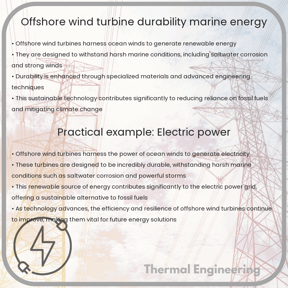
Offshore wind turbines are pivotal in harnessing the renewable and powerful energy resources provided by marine environments. These turbines generate electricity by capturing the kinetic energy of wind blowing over the ocean’s surface, a process increasingly vital in our pursuit of sustainable energy solutions. Central to the effectiveness of offshore wind farms is the durability of their turbines, which must withstand harsh maritime conditions.

Components and Operation of Offshore Wind Turbines

Offshore wind turbines typically consist of several key components:

  • The Tower: A tall structure made mostly of steel, designed to support the weight of the nacelle and blades.
  • The Nacelle: Houses the generator, gearbox, drive train, and other mechanical components.
  • The Rotor Blades: Capture wind energy and convert it into rotational mechanical energy.
  • The Foundation: Anchors the turbine to the seabed; can be fixed or floating depending on the water depth.

These turbines operate on a simple principle: wind energy turns the rotor blades around a rotor, which spins a generator to produce electricity.

Challenges in Durability

Offshore wind turbines face unique environmental challenges that can impact their durability and efficiency. The major factors include:

  • Corrosion: Saltwater exposure can lead to significant corrosion of metal components.
  • Wind and Wave Loads: Strong marine winds and harsh waves place immense stress on the structural integrity of the turbines.
  • Biofouling: Marine organisms can accumulate on the structures, adding weight and potentially damaging materials.

Engineers use advanced materials and protective coatings to mitigate these issues. Additionally, regular maintenance and monitoring are critical to manage wear and tear over time.

Engineering Innovations Enhancing Turbine Durability

Innovative engineering solutions have been developed to enhance the durability of offshore wind turbines:

  • Advanced Materials: Using composite materials for blades and special anti-corrosion coatings can significantly reduce wear from environmental exposure.
  • Condition Monitoring Systems: These systems use sensors to continuously check the condition of turbine components, predicting and preventing failures before they occur.
  • Optimized Foundation Designs: Floating foundations, for example, can be used in deeper waters where fixed structures are not feasible, allowing turbines to operate in previously inaccessible sites.

Role of Offshore Wind in Marine Energy

Offshore wind energy is a substantial component of the broader marine energy landscape, which includes tidal and wave energy. These technologies are critical in the transition towards renewable energy sources, offering three significant advantages:

  • Continuity: Unlike other renewable sources like solar, marine energies can be continuous, with wind and waves available day and night.
  • High Energy Density: Water has a higher density than air, enabling more energy to be captured per square meter in ocean-based systems compared to land-based systems.
  • Spatial Efficiency: Offshore wind farms can be located far from shore, minimizing visual and environmental impacts while capitalizing on stronger, more consistent winds.

In summary, offshore wind turbines not only embody a clean energy solution but are also a testament to engineering innovation aimed at overcoming the formidable challenges posed by the marine environment. Their continuing development and deployment worldwide signify a promising trajectory towards sustainable global energy systems.

Metering Pump | Precision Dosing & Water Treatment

Explore the role, function, and types of metering pumps in precision dosing and industrial applications.

Metering Pump | Precision Dosing & Water Treatment

Understanding Metering Pumps: Precision Dosing and Water Treatment

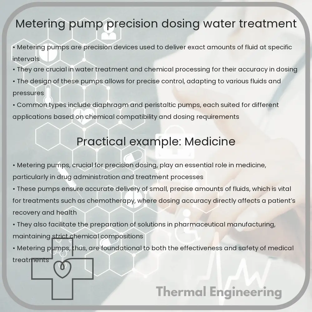
Metering pumps, also known as dosing pumps, play a crucial role in various industrial and municipal applications by delivering precise volumes of liquids in a controlled manner. These pumps are essential for processes where the accurate dosing of chemicals, reagents, or other substances is necessary, such as in water treatment, chemical processing, and pharmaceutical manufacturing.

How Metering Pumps Work

Metering pumps function by creating a flow of liquid using a reciprocating diaphragm or piston. This action allows the pump to precisely control the volume of fluid delivered in each stroke, ensuring accurate dosing. The main components of a metering pump include:

  • Pump head: Contains the wetted parts and valves necessary for the suction and discharge processes.
  • Diaphragm or piston: Moves back and forth to draw fluid into the pump chamber on the inlet stroke and push it out on the discharge stroke.
  • Drive mechanism: Responsible for converting the rotational motion of the motor into the reciprocating motion needed to operate the diaphragm or piston.
  • Control system: Enables operators to set the flow rate and adjust the stroke length and speed, controlling the dosing precision.

Types of Metering Pumps

Metering pumps can be categorized into several types based on their mechanism and performance requirements:

  1. Diaphragm Pumps: Use a flexible membrane to separate the liquid being pumped from the moving parts, preventing contamination and handling corrosive liquids effectively.
  2. Piston Pumps: Utilize a rigid piston to push the fluid through the pump chamber, suitable for high-pressure applications.
  3. Peristaltic Pumps: Employ a rotating roller to compress and release a flexible tube, moving the fluid without direct contact with mechanical parts.

Applications in Water Treatment

In water treatment, metering pumps are deployed for their ability to administer precise amounts of disinfectants, pH adjusters, coagulants, and other treatment chemicals. Their applications include:

  • Disinfection: Automating the injection of chlorine or other disinfectants to kill bacteria and pathogens in water supplies.
  • pH Adjustment: Adding acids or bases to maintain the optimal pH level for various stages of water treatment.
  • Flocculation: Dosing flocculants to promote the aggregation of particles, making them easier to remove during sedimentation and filtration.

Choosing the Right Metering Pump

When selecting a metering pump for a particular application, several factors need to be considered:

  • Chemical Compatibility: The materials of the pump should be compatible with the chemicals being dosed to avoid corrosion or degradation.
  • Flow Rate Requirements: The pump must be capable of achieving the required flow rates, which can vary depending on the process needs.
  • Pressure Specifications: The pump should be able to handle the system pressure, especially in high-pressure dosing applications.
  • Accuracy and Reliability: Essential for maintaining the effectiveness and safety of the dosing process, especially in critical applications like water treatment.

Conclusion

Metering pumps are indispensable in industries where precision and reliability in fluid handling are paramount. Their ability to accurately dose chemicals ensures efficient operations in water treatment, pharmaceuticals, and other sectors. By understanding the different types of metering pumps and their applications, industries can better choose the right pump that matches their specific needs, optimizing both performance and cost-effectiveness.

Rotary Valve | Material Handling & Pneumatic Systems

Learn about rotary valves, essential components in material handling and pneumatic systems for efficient bulk material transfer and airlock maintenance.

Rotary Valve | Material Handling & Pneumatic Systems

Understanding Rotary Valves: Essentials for Material Handling and Pneumatic Systems

Rotary valves play a crucial role in material handling and pneumatic conveying systems, enabling efficient, controlled transfer of bulk solid materials from one part of the system to another. Commonly used in industries such as agriculture, chemical, pharmaceutical, and food processing, rotary valves not only help in material transfer but also ensure that the system maintains a proper airlock condition. This article outlines the basic operation, types, and considerations important in utilizing rotary valves in engineering applications.

What is a Rotary Valve?

A rotary valve, also known as a rotary airlock or rotary feeder, functions as a component in bulk material handling systems designed for metering, feeding, and discharge duties. The device typically consists of a rotor with multiple vanes, housed inside a cylindrical casing, which turns to transport material from the inlet above the valve to the discharge point below it while maintaining an air seal.

Types of Rotary Valves

  • Drop-Through Rotary Valve: Often used in gravity feed applications, the drop-through design allows materials to fall directly through the valve from the inlet above to the discharge below the rotor.
  • Blow-Through Rotary Valve: In this type, the conveying medium (usually air or other gases) is blown through the rotor pockets, effectively assisting in the pneumatic conveying of material.
  • Side Entry Rotary Valve: Designed for materials that are more difficult to handle, the side entry valve reduces the shearing actions on the product by allowing it to enter the rotor from the side.

Principle of Operation

The rotary valve’s operation is relatively straightforward. As the rotor turns, its pockets are filled with material at the top of the valve. Continuous rotation leads these pockets past the valve’s body and to the discharge opening. The precise volume of each pocket ensures a consistent amount of material is transferred during each cycle, which is crucial for applications requiring accurate dosing and flow control.

Engineering Considerations

  • Material Characteristics: Understanding the material’s properties, such as particle size, abrasiveness, and corrosiveness, is vital to select the right type of rotary valve and ensure longevity and effectiveness.
  • Valve Sealing: Proper sealing is essential to prevent air leakage that can reduce the efficiency of pneumatic conveying systems. Selection of seal design and maintenance should be emphasized.
  • Rotational Speed: The speed of the rotor affects both the rate of material flow and the pressure differential across the valve. It is important to balance operational speed to avoid excessive wear or system blockages.
  • Temperature and Pressure Conditions: Rotary valves must be designed to withstand the specific temperature and pressure conditions of their operating environment, particularly when handling hot or chemically active materials.

Applications of Rotary Valves

Rotary valves find their application in numerous systems where bulk solids need to be metered and controlled as they are moved between processes or storage areas. They also serve as critical components in systems requiring airlock functionalities to separate different pressure zones while transferring the material. These applications include:

  • Feeding materials into a pneumatic conveying system
  • Discharging powders from cyclones and silos
  • Temperature controlled processing
  • Dust collection systems

In conclusion, rotary valves are indispensable in fields that involve the handling and processing of powders and bulk materials. Correct selection and maintenance of these valves ensure the efficiency and reliability of material handling and pneumatic systems, while also providing essential control in various industrial processes. Understanding these basic principles and considerations can aid engineers and technicians in optimizing their use of rotary valves in diverse industrial settings.

Plunger Pump | High-Pressure & Durability in Washing

Learn about plunger pumps, essential for high-pressure water delivery in washing and cleaning applications due to their efficiency and durability.

Plunger Pump | High-Pressure & Durability in Washing

Understanding the Plunger Pump: High-Pressure and Durability in Washing Applications

Plunger pumps, a type of positive displacement pump, are crucial in applications requiring high-pressure water delivery. They are especially favored in industries for their efficiency and durability in washing and cleaning operations. This article explores the mechanics of plunger pumps and why they are preferred in high-pressure washing tasks.

The Basics of Plunger Pump Operation

A plunger pump operates by moving a plunger back and forth in a cylinder. The movement is typically powered by an electric motor or an internal combustion engine. As the plunger moves, it creates a vacuum, pulling the cleaning fluid (usually water) into the cylinder through an inlet valve. On the return stroke, the water is pushed out through the outlet valve under high pressure.

  • Plunger Movement: Responsible for drawing in and expelling fluid.
  • Inlet Valve: Allows fluid entry when the plunger retracts.
  • Outlet Valve: Opens to expel fluid under pressure as the plunger pushes forward.

Components Critical for High-Pressure Generation

The design and robustness of plunger pumps allow them to achieve high pressures necessary for effective cleaning.

  • High-strength Materials: Components like plungers and cylinders are made from materials capable of withstanding high stress and wear.
  • Tight Seals: High-quality seals prevent leakage of water at high pressures, improving the efficiency and minimizing maintenance needs.
  • Precision Engineering: Precision in manufacturing ensures minimal internal friction, leading to better performance at high pressures.

Applications in High-Pressure Washing

Due to their high-pressure output, plunger pumps are ideal for applications requiring intense cleaning power, such as:

  • Industrial Cleaning: Removing heavy grime and contaminants from machinery and surfaces.
  • Car Washes: Delivering powerful wash cycles that quickly remove dirt without damaging the vehicle.
  • Surface Preparation: Preparing surfaces for painting or coating by effectively removing old paint, rust, or other residues.

Advantages of Using Plunger Pumps in Washing

Plunger pumps offer several benefits that make them an excellent choice for high-pressure washing applications:

  • Efficiency: Capable of converting a high percentage of the energy they consume into effective pumping power.
  • Durability: The robust construction and minimal wear parts reduce the frequency of maintenance and replacement.
  • Versatility: Able to handle various types of liquids and additives used in specialized washing processes.

Conclusion

In summary, plunger pumps are a preferred choice in tasks that require high pressure due to their efficient operation, high durability, and versatility. Whether in industrial cleaning, car washes, or surface preparation, plunger pumps offer reliable performance and superior results, making them an indispensable tool in many washing applications.

Wells Turbine | Ocean Energy & Airflow Design

Learn about the Wells Turbine, its design, operation, and role in converting ocean wave energy into electrical power efficiently.

Wells Turbine | Ocean Energy & Airflow Design

Understanding the Wells Turbine: Harnessing Ocean Energy through Airflow Design

The Wells Turbine is an innovative mechanical device designed to convert ocean wave energy into electrical power. Named after its inventor, Professor Alan Wells from Queen’s University Belfast in the 1970s, this turbine is a key component in wave energy conversion systems. Its unique design allows for continuous electricity generation from the oscillating airflow caused by ocean waves.

Principles of Operation

The Wells Turbine operates on a simple yet effective principle: it utilizes the bi-directional airflow generated by the motion of ocean waves in an Oscillating Water Column (OWC). As waves rise and fall, air is pushed in and out of a chamber. This oscillating airflow drives the turbine’s blades, which are symmetrically designed to rotate in a single direction regardless of the airflow direction. This consistency in rotation removes the need for complex control systems to handle direction changes, enhancing the reliability and efficiency of the turbine.

Key Design Components

  • Axial Flow Design: The turbine blades are aligned parallel to the direction of the airflow, typical of axial flow turbines. This arrangement maximizes the conversion of air kinetic energy into rotational mechanical energy.
  • Symmetrical Blades: Each blade’s aerodynamic profile is symmetrical, meaning it can effectively capture energy from air moving in either direction through the turbine.
  • Low Cut-in Speed: The Wells Turbine operates effectively at low wind speeds, which is ideal for environments where wave-induced air velocities are relatively low.

Challenges in Efficiency and Improvements

While the Wells Turbine presents a remarkable solution for wave energy conversion, several challenges affect its overall efficiency:

  • Blade Stall: At higher air velocities, the turbine may experience blade stall, which can lead to a significant drop in performance. This occurs when the angle of attack on the blades becomes too great, causing airflow disruption and loss of lift.
  • Noise and Vibration: The turbine’s operation can generate considerable noise and vibrations, potentially impacting the structural integrity of the installation and reducing the comfort of nearby habitats.

To address these issues, ongoing research focuses on blade design optimization and the integration of variable pitch blades, which adjust their angle relative to the airflow to maintain optimal performance across varying operational conditions.

Applications and Future Prospects

The Wells Turbine is primarily used in OWC wave energy converters, which are suited for coastal regions with strong wave activity. The technology has been deployed in several pilot projects around the world, contributing to the renewable energy mix and supporting coastal community power needs.

Looking toward the future, improvements in materials science, blade design, and computational fluid dynamics (CFD) modeling promise to enhance the performance and reliability of the Wells Turbine. Increased efficiency and reduced costs are critical for scaling up this technology and achieving wider adoption in the global push towards sustainable energy solutions.

In conclusion, the Wells Turbine stands out in the field of renewable energy for its unique solution to converting ocean wave energy into usable power. With continuous advancements, it holds the potential to play a significant role in the sustainable management of our planet’s vast ocean energy resources.