Facebook Instagram Youtube Twitter

Gear Pump | Operation, High Viscosity Fluid Transfer

Learn about gear pumps, their operation, and how they efficiently transfer high viscosity fluids in various industrial applications.

Gear Pump | Operation, High Viscosity Fluid Transfer

Understanding Gear Pumps: Operation and High Viscosity Fluid Transfer

Gear pumps are a type of positive displacement pump, widely used in various industries to transport high viscosity fluids. They operate by meshing two or more gears together, trapping fluid between the teeth, and mechanically transporting it around the casing to the discharge point. This article explains the basic operation of gear pumps and their effectiveness in handling high viscosity fluids.

Principles of Operation

The basic components of a gear pump include the gears, casing, drive shaft, and bearings. Most gear pumps use either external or internal gears. External gear pumps feature two identical gears rotating against each other with intermeshed teeth, whereas internal gear pumps consist of a larger outer ring gear and a smaller, internal pinion gear. The operation cycle in gear pumps can be described as follows:

  • Intake: As the gears come out of mesh on the intake side of the pump, they create expanding volume. This expansion creates a vacuum that allows the fluid to flow into the cavities between the teeth.
  • Transport: As the gears rotate, the fluid is trapped between the teeth and the pump casing, thereby carrying it from the intake side to the discharge side.
  • Discharge: When the gears re-mesh on the discharge side, the volume is reduced, and the fluid is forced out of the pump.

Handling High Viscosity Fluids

Gear pumps are particularly effective in transferring high viscosity fluids. The efficiency of gear pumps in handling such fluids can be attributed to several factors:

  • Positive Displacement: Gear pumps displace a constant amount of fluid for each revolution, which is beneficial for moving thick fluids that require stable and consistent flow rates.
  • Low Internal Slippage: The tight tolerances in the design of gear pumps minimize the internal slippage of fluid, ensuring efficient transfer even at higher viscosities.
  • Self-Priming Capability: Gear pumps can operate with high suction lift, making them capable of handling heavy and viscous fluids without needing a flooded suction.

The capacity of a gear pump to handle viscous fluids is typically defined by its viscosity limits, which can vary depending on the design and material of the pump. Commonly, gear pumps can handle fluids with viscosities as low as 1 centipoise (cps) and as high as 1,000,000 cps.

Applications in Industries

Due to their robust nature and ability to handle a variety of fluid viscosities, gear pumps are extensively used in numerous applications, including:

  • Chemical Processing: Transfer of adhesives, resins, paint, and other chemicals.
  • Food and Beverage: Handling syrups, oils, and pastes.
  • Pharmaceutical: Precise dosing of thick creams and gels.
  • Petroleum: Pumping crude oil, fuel oils and lubricants.

Understanding the operation and capabilities of gear pumps can aid in choosing the right pump for specific applications, especially when dealing with high viscosity fluids. Their efficiency, durability, and ability to provide steady, controllable fluid delivery makes them an invaluable tool in many engineering and industrial processes.

Conclusion

Gear pumps are a vital component in the functionality of numerous industrial sectors. Their ability to efficiently handle high viscosity fluids, coupled with their straightforward operation and maintenance, renders them indispensable for businesses needing reliable and effective fluid transfer solutions.
Ion Exchange System | Process, Water Softening, Treatment

Learn about ion exchange systems, their roles in water treatment, softening, and purification, and how they function through cation and anion exchanges.

Ion Exchange System | Process, Water Softening, Treatment

Understanding Ion Exchange Systems

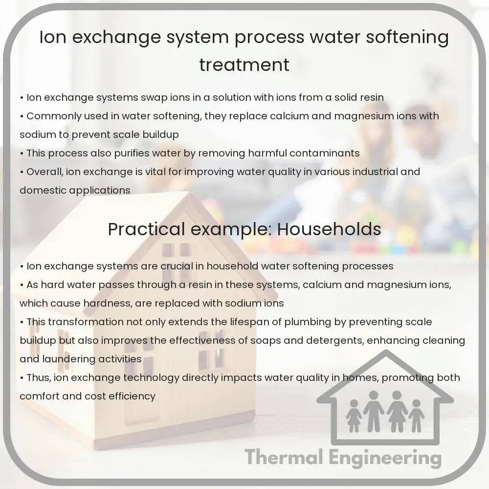
An ion exchange system is a vital tool in the world of water treatment and softening. This technology utilizes a process where ions are exchanged between a solution and an ion exchange material. It is widely used for water purification, chemical recovery, and to treat water hardness. In this article, we’ll explore how ion exchange systems work, their applications, and the benefits of their use.

The Process of Ion Exchange

At its core, ion exchange is a reversible chemical reaction where ions are swapped between a solid substance (ion exchanger) and a liquid (water). The ion exchange material commonly comes in the form of small resin beads that are composed of organic polymers capable of releasing certain ions into the liquid and absorbing others.

Types of Ion Exchange

  1. Cation Exchange – Cations (positively charged ions) in the water are replaced with hydrogen (H+) or sodium (Na+) ions. Used primarily for water softening and pH adjustment.
  2. Anion Exchange – Anions (negatively charged ions) are exchanged for hydroxide (OH–) ions, which combine with H+ from cation exchange to form water (H2O). This process is useful in demineralizing water.

Water Softening Through Ion Exchange

One of the most common applications of ion exchange is water softening. Hard water contains high levels of calcium (Ca2+) and magnesium (Mg2+) ions, which can cause scaling in pipes and inefficiency in detergents. In a water softening ion exchange system, hard water passes through a resin that is charged with sodium ions. The calcium and magnesium ions in the water are replaced by the sodium ions from the resin, resulting in softer water.

Key Benefits and Applications

  • Improved Water Quality – Reduces hardness, removes contaminants like iron, manganese, and arsenic, and minimizes scale buildup in plumbing systems.
  • Industrial Applications – Used in a variety of industries for boiler feed water treatment, in chemical production, and metal extraction processes.
  • Waste Water Treatment – Helps in the recovery of valuable minerals from wastewater and reduces pollutants before discharge.

Considerations in Ion Exchange System Design

Designing an effective ion exchange system requires careful consideration of several factors:

  • Water Chemistry – Understanding the specific contaminants and the total ionic content of the water is essential.
  • Resin Type – Selection between cationic and anionic resins or mixed-bed resins based on the application.
  • Regeneration Process – The method and frequency of regenerating the resin with a high concentration of a salt solution, typically sodium chloride (NaCl) for softening applications.
  • System Capacity – The size and flow rates must be matched to the facility’s needs.

Ion exchange is a sophisticated yet simple method for improving water quality, facilitating various industrial processes, and contributing to environmental sustainability. By understanding its process, applications, and design considerations, stakeholders can better implement and benefit from this technology.

Desiccant Dehumidifier | Working, Moisture Control, Use

Learn about desiccant dehumidifiers, essential for moisture control in various environments, differing from traditional dehumidifiers by using absorbent materials.

Desiccant Dehumidifier | Working, Moisture Control, Use

Understanding Desiccant Dehumidifiers

Desiccant dehumidifiers are vital tools used extensively in various industries and residential settings to control humidity, protect goods from moisture damage, and improve comfort levels. These devices differ from conventional refrigerative dehumidifiers because they use a desiccant material to absorb moisture from the air directly.

How Desiccant Dehumidifiers Work

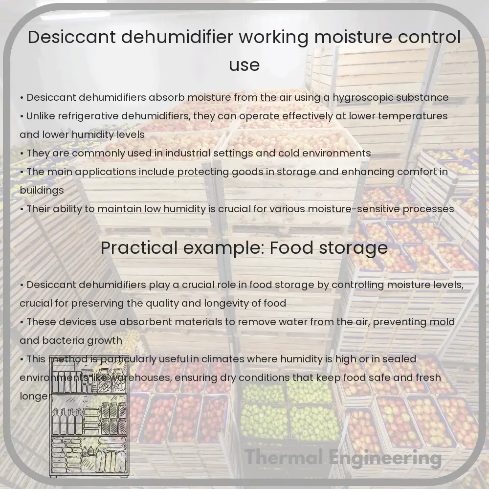
Desiccant dehumidifiers operate based on a simple yet effective principle. They are equipped with a desiccant material, often silica gel or molecular sieves, which has a high affinity for water vapor. The operation of a desiccant dehumidifier can be divided into two primary cycles: adsorption and regeneration.

  1. Adsorption: During this phase, humid air is drawn into the dehumidifier through a duct. As the air passes through, it comes into contact with the desiccant material. The desiccant material adsorbs the moisture from the air, and the dried air is then released back into the room or the designated dry area.
  2. Regeneration: To continue efficiently absorbing moisture, the desiccant must be dried or “regenerated. This is typically achieved by heating the desiccant, which releases the captured moisture into a separate air stream. This moist, warm air is then vented outside the area being dried.

Desiccant dehumidifiers can operate effectively at lower temperatures and lower humidity levels compared to refrigerative types, as their performance is not reliant on dew point temperature.

Moisture Control and Adjustability

The efficiency of desiccant dehumidifiers in moisture control is one of their standout features. They can reduce the humidity to much lower levels than refrigerative dehumidifiers. This capability makes them ideal for environments where maintaining a specific, low humidity level is crucial, such as in pharmaceutical production, food storage, or ice rinks.

These units commonly feature humidity controls that allow users to set a desired humidity level. Once the ambient humidity reaches the set point, the dehumidifier can cycle off, conserving energy and reducing wear on the desiccant material.

Common Uses of Desiccant Dehumidifiers

  • Industrial Applications: Desiccant dehumidifiers are widely used in manufacturing processes where moisture needs to be strictly controlled to prevent product degradation, clumping, or other quality issues.
  • Water Damage Restoration: These devices are critical in environments affected by water damage as they can quickly and effectively dry out wet areas, preventing the growth of mold and mildew.
  • Storage Solutions: They are used in storage facilities, particularly for delicate items such as electronics or artwork that are sensitive to moisture.
  • HVAC Systems: Integrated into heating, ventilation, and air conditioning systems, desiccant dehumidifiers help in maintaining comfort levels and avoiding condensation problems in buildings.

In conclusion, desiccant dehumidifiers play a crucial role in various applications by efficiently controlling moisture levels in the air. Their ability to function effectively under a broad range of conditions, coupled with precise humidity control, makes them indispensable in many industrial and residential scenarios.

Hydraulic Press | Operation, Forming & Molding Applications

Learn how a hydraulic press operates using Pascal’s Law to exert high force for industrial forming and molding applications.

Hydraulic Press | Operation, Forming & Molding Applications

Understanding the Hydraulic Press

The hydraulic press is a powerful device used in many industrial processes, particularly in the areas of forming and molding materials. Utilizing Pascal’s Law, which states that pressure applied to a confined fluid is transmitted undiminished throughout the fluid, the hydraulic press generates a significant amount of force from a relatively small input force.

How Does a Hydraulic Press Operate?

At its core, a hydraulic press consists of two cylinders that are connected and filled with a fluid—typically oil. One cylinder is smaller and referred to as the plunger or piston, and the other is larger, known as the ram. When a force is applied to the plunger, it increases the pressure of the fluid, which is then transmitted to the larger ram. This process effectively amplifies the force exerted on the ram, which can then be used to perform various tasks such as crushing, molding, or shaping materials.

The Basic Components of a Hydraulic Press

  • Hydraulic cylinders: Comprise the piston and the ram, crucial for the pressure generation and transmission.
  • Pump: Used to move the hydraulic fluid from the reservoir to the cylinders, enabling the press to generate force.
  • Reservoir: Holds the hydraulic fluid.
  • Valves: Control the flow of hydraulic fluid, directing it where needed and maintaining system pressures.

Forming and Molding Applications

Hydraulic presses are integral to the forming and molding of materials across various industries. Here are a few common applications:

  1. Metal forming: Used in the automotive and aerospace industries to shape metal parts like car bodies and aerostructure components.
  2. Plastic molding: In manufacturing, hydraulic presses are used for compression molding and thermoforming of plastic parts.
  3. Ceramic molding: Hydraulic presses offer the precise control needed for producing ceramic products.

Advantages of Using a Hydraulic Press

Hydraulic presses offer several benefits over mechanical and pneumatic systems, including:

  • High force capability: Capable of generating forces that are significantly greater than their mechanical or pneumatic counterparts.
  • Precise control: Offers excellent control over the pressing speed and force, which is crucial for quality manufacturing.
  • Energy efficiency: Consumes power only during the operation stroke, unlike other systems which may need continuous power or air supply.
  • Versatility: Adjustable parameters allow for a wide range of operations, accommodating different materials and requirements.

Challenges and Considerations

While hydraulic presses are advantageous in many aspects, they also come with challenges that must be managed:

  • Maintenance: Regular maintenance is required to prevent leaks and ensure the integrity of the hydraulic fluid system.
  • Operational speed: Generally slower than mechanical presses, which may affect productivity in high-volume industries.
  • Initial cost: Typically, hydraulic presses are more expensive than other types of presses, which might be a barrier for small-scale operations.

In summary, the hydraulic press plays a crucial role in the forming and molding of materials in modern manufacturing. Its operation based on Pascal’s Law allows it to exert enormous force with minimal input, making it indispensable in many industrial applications. However, like all technologies, it must be utilized thoughtfully and maintained properly to maximize its benefits.

Chilled Beam System | Design, Energy Saving Cooling/Heating

Learn about chilled beam systems, their design, advantages, and how they improve energy efficiency in modern buildings.

Chilled Beam System | Design, Energy Saving Cooling/Heating

Understanding Chilled Beam Systems: Design and Energy-Saving Advantages

Chilled beam systems are a type of air conditioning solution that is becoming increasingly popular in modern buildings due to their energy efficiency and space-saving design. These systems use water as the primary cooling medium and are typically used in commercial, institutional, and sometimes residential settings. This article explores the design of chilled beam systems, how they function, and their advantages, particularly in terms of energy savings and heating/cooling effectiveness.

Basics of Chilled Beam Systems

At its core, a chilled beam system consists of two main components: a chilled beam unit (typically mounted on the ceiling) and a water chilling system. The chilled beam unit itself is a passive or active device that uses chilled water to cool the air in a room. There are two primary types of chilled beam systems:

  • Passive Chilled Beams (PCBs): These utilize the natural convection currents to cool or heat a space. As warm air rises towards the ceiling, it is cooled by the chilled beam and naturally descends back into the room as it cools, thus creating a convection current.
  • Active Chilled Beams (ACBs): These have integrated air supply, where conditioned (cooled or heated) fresh air is pushed through nozzles on the beam, enhancing the convection effect and providing better controlled airflow within the space.

Design Considerations

Effective implementation of chilled beam technology in a building’s HVAC system requires careful design consideration:

  • Room Layout: The efficiency of chilled beams depends highly on the room configuration and ceiling height. High ceilings are advantageous for PCBs due to the natural convection currents.
  • Humidity Control: Chilled beams require careful handling of humidity levels to prevent condensation. Proper ventilation and dehumidification are crucial to avoid moisture-related issues.
  • Load Estimation: Accurate calculation of thermal loads is essential to size the system correctly and to ensure efficient operation without overcooling or overheating the space.

Energy Saving and Efficiency

Chilled beam systems offer several benefits over traditional forced air systems concerning energy efficiency and environmental impact:

  1. Reduced Air Handling: Since chilled beams transfer most of the cooling directly via water, less air needs to be conditioned, which reduces fan energy consumption significantly.
  2. Water-based Cooling: Water has a higher specific heat capacity compared to air, making it a more efficient medium for heat transfer. This allows chilled beam systems to use less energy to achieve the same level of thermal comfort.
  3. Low Maintenance: With fewer moving parts than traditional HVAC systems, chilled beams are less prone to breakdowns, further reducing energy use and maintenance costs.

Challenges and Considerations

While chilled beam systems have considerable benefits, there are also challenges that must be addressed:

  • Air Quality: Since passive chilled beams do not actively introduce or circulate new air, adequate ventilation systems must be included to maintain indoor air quality.
  • Architectural Integration: Chilled beams require integration into the architectural design of the building, which can be a challenge in retrofit projects.
  • Initial Costs: The upfront cost for installing chilled beam systems can be higher than traditional systems, though the lower operational costs can offset this over time.

In conclusion, chilled beam systems offer a highly efficient and space-saving alternative to conventional air conditioning systems, particularly suitable for applications where airflow control, reduced noise, and energy efficiency are critical. With proper design and installation, their advantages can significantly outweigh the initial investment and operational challenges.

Thermal Wheel | Heat Recovery, HVAC Efficiency

Learn about thermal wheels, devices enhancing HVAC efficiency through effective heat recovery.

Thermal Wheel | Heat Recovery, HVAC Efficiency

Understanding Thermal Wheels: Enhancing HVAC Efficiency through Heat Recovery

A thermal wheel, also known as a rotary heat exchanger or heat recovery wheel, plays a crucial role in improving the energy efficiency of heating, ventilation, and air conditioning (HVAC) systems. This device facilitates heat transfer between incoming and outgoing air streams, significantly reducing the energy required to heat or cool buildings. In this article, we explore how thermal wheels work, their applications, and the benefits they offer in HVAC systems.

How Does a Thermal Wheel Work?

A thermal wheel consists of a large circular disc, made from material that easily absorbs and conducts heat. As the wheel rotates, it passes alternately through the incoming and outgoing air streams. During this process, the wheel absorbs heat from the warmer air stream and transfers it to the colder air stream. This operation is continuous and consists of two key phases:

  • Heat Absorption: When the warmer air stream heats up the segments of the wheel, the material within the wheel absorbs and retains this heat.
  • Heat Release: As the wheel rotates into the colder air stream, the previously absorbed heat is released, warming up the incoming cooler air.

The effectiveness of a thermal wheel is often measured in terms of its heat recovery efficiency, which can significantly impact overall HVAC system efficiency.

Materials and Design Considerations

The choice of material and the design of the thermal wheel are critical for its efficiency. Common materials used include aluminum, due to its excellent thermal conductivity and corrosion resistance. Some advanced wheels might also incorporate a desiccant material to enable moisture transfer, which is particularly beneficial in humid climates.

The design factors like wheel diameter, rotation speed, and airflow rates must be optimized based on specific HVAC system requirements. Proper sealing around the wheel is essential to prevent air leakage between the supply and exhaust air streams.

Applications of Thermal Wheels

Thermal wheels are widely used in commercial and industrial facilities where large volumes of air must be conditioned. Typical applications include:

  • Office buildings
  • Hospitals
  • Schools and universities
  • Manufacturing facilities

By recovering waste heat from exhaust air, these systems can significantly reduce the demand on heating and cooling equipment, thereby lowering energy consumption and operational costs.

Benefits of Using Thermal Wheels in HVAC Systems

Incorporating thermal wheels into HVAC systems offers several benefits:

  • Energy Savings: By recycling heat from the exhaust air, less energy is required to maintain desired indoor temperatures, resulting in lower utility bills.
  • Reduced Environmental Impact: Lower energy consumption leads to reduced greenhouse gas emissions, contributing to a smaller carbon footprint.
  • Improved Indoor Air Quality: Since thermal wheels can also transfer moisture, they help in maintaining optimal humidity levels, enhancing indoor comfort and air quality.
  • Extended Equipment Lifespan: With decreased load on heating and cooling systems, the wear and tear on equipment is reduced, potentially extending the lifespan of these systems.

Leveraging the thermal efficiency and simplicity of design, thermal wheels offer an effective means to enhance the sustainability and cost-effectiveness of HVAC systems. As technology advances, the integration of these devices in modern climate control solutions is likely to expand, further improving energy efficiency and environmental sustainability.

Conclusion

Thermal wheels represent a pivotal technology in modern HVAC systems, enabling significant energy recovery and efficiency improvements. By understanding the principles and applications of thermal wheels, engineers and facility managers can better design systems that not only save on costs but also promote environmental sustainability. As global focus on energy efficiency continues to intensify, the role of thermal wheels in heating and cooling solutions becomes increasingly important.

Thermal stress analysis in materials

Learn about thermal stress in materials, its causes, calculation, and impact on engineering designs, encompassing expansion, contraction, and structural integrity.

Thermal stress analysis in materials

Understanding Thermal Stress in Materials

Thermal stress occurs in materials when changes in temperature cause the material to expand or contract. This expansion or contraction is often constrained, leading to the development of stress within the material. Understanding thermal stress is crucial in engineering, as it impacts the design and durability of structures ranging from small electronic components to large bridges.

What Causes Thermal Stress?

Most materials expand when heated and contract when cooled, a property known as thermal expansion. The degree to which materials expand or contract is quantified by their thermal expansion coefficient, typically denoted as α (alpha). The thermal expansion coefficient is unique to each material and determines how much it will expand or contract per degree change in temperature.

Thermal stress arises when thermal expansion or contraction is restrained by adjacent structures or the material itself. This restraint can be due to external structures or due to variations in temperature across parts of the material that expand or contract at different rates.

Calculating Thermal Stress

The basic formula used to calculate thermal stress (σ) in a uniaxial, homogeneous, and isotropic material is given by:

\[ \sigma = E \alpha \Delta T \]

  • E is the modulus of elasticity of the material (also known as Young’s modulus).
  • α is the coefficient of thermal expansion.
  • ΔT is the change in temperature.

This equation assumes that the entire strain produced by the temperature change is converted into stress, which is typically the case in fully constrained conditions.

Factors Influencing Thermal Stress

  • Material Properties: Different materials react differently under thermal stress owing to variations in their thermal expansion coefficients and elastic moduli.
  • Geometric Constraints: The shape and size of a material can affect how it experiences thermal stress. For example, thinner materials might heat up and cool down faster, leading to more rapid changes in stress.
  • Temperature Gradient: A non-uniform temperature distribution can lead to differential expansion, intensifying the stress within the material.

Real-World Applications and Considerations

In engineering, thermal stress analysis is crucial for:

  • Designing components that undergo significant temperature changes, such as engine parts, cooking utensils, and spacecraft.
  • Ensuring the structural integrity of buildings and bridges, which might experience various temperature changes throughout the seasons.
  • Electronics manufacturing, particularly in selecting materials that can withstand the thermal cycles during device operation.

Moreover, engineers must consider the effects of repeated thermal cycling, which can lead to fatigue and eventual failure of materials. This is particularly important in applications involving frequent on-and-off cycles, such as in automobile engines or heating systems.

Conclusion

Thermal stress is a vital consideration in the design and maintenance of a wide range of engineering systems. By understanding how materials respond to changes in temperature, engineers can devise strategies to mitigate the risks associated with thermal expansion and contraction, enhancing the durability and performance of materials in diverse applications.

Pulsation Dampener | Function, Pressure Control in Pumps

Learn about the role and functionality of pulsation dampeners in controlling pressure fluctuations in hydraulic pumping systems.

Pulsation Dampener | Function, Pressure Control in Pumps

Understanding Pulsation Dampeners: Their Role and Importance in Pressure Control in Pumps

Pulsation dampeners are critical components used in various pumping systems to ensure a smooth flow and to reduce fluctuations in pressure that occur during the pumping cycle. By understanding how pulsation dampeners function and their role in pressure control, both engineers and technicians can optimize the performance of hydraulic pumping systems and extend the life expectancy of their equipment.

What is a Pulsation Dampener?

A pulsation dampener is a device designed to absorb and mitigate the pulsations and vibrations in the hydraulic fluid flow generated by reciprocating pumps. These devices are crucial in maintaining the stability of the flow rate and pressure within pipelines, therefore protecting the system components from potential damage due to excessive vibrations and fluctuations.

How Does a Pulsation Dampener Work?

The principle operation of a pulsation dampener lies in its ability to adjust the pressure variations using either an air cushion or a diaphragm within its chamber. Here’s a breakdown of the working mechanism:

  • When a pump pushes fluid through a pipe, it typically does so in distinct pulses, especially in reciprocating pumps like piston or plunger types.
  • The pulsation dampener is installed proximate to the pump’s discharge point to intercept these pulses.
  • Inside the dampener, a flexible diaphragm or bladder separates the hydraulic fluid from a pressurized gas chamber (usually filled with nitrogen).
  • As pulses from the pump enter the dampener, the diaphragm flexes, absorbing the energy of the pulse and thereby smoothing out the flow on the other side.

This absorption and subsequent release of pressure waves help maintain a uniform flow rate and minimize pressure spikes and drops, leading to a more efficient system operation.

Benefits of Using Pulsation Dampeners

  1. Reduced Mechanical Stress: By dampening pulsations, these devices decrease the stress on pipeline and pump components, increasing their lifespan and reducing maintenance requirements.
  2. Improved Efficiency: Smoothing out the flow allows for consistent system operation and reduces energy consumption by avoiding pressure peaks that require additional power to overcome.
  3. Noise Reduction: Pulsation dampeners help in lowering noise levels produced by vibrations and pulsations, thereby contributing to a more pleasant working environment.
  4. Safety: Regular pulsations can lead to fatigue failures in pipe systems, potentially causing hazardous leaks. Dampeners mitigate these risks substantially.

Types of Pulsation Dampeners

Generally, there are two predominant types of pulsation dampeners:

  • Diaphragm Dampeners: These employ a diaphragm to separate the fluid from the compressed gas (air or nitrogen). Adjustments can be made to the pressure of the gas to optimize performance.
  • Bladder Dampeners: Similar in functionality, these use a bladder instead of a diaphragm, offering easier maintenance and replacement procedures.

Conclusion

Pulsation dampeners play a pivotal role in ensuring the operational integrity and efficiency of pumping systems. By effectively managing pressure fluctuations, they prevent wear and tear on system components, reduce operational costs, and maintain safety standards. For engineers and maintenance technicians, understanding and utilizing the correct type of pulsation dampener is essential for optimizing the performance of hydraulic systems.

Gravity Separator | Mechanism, Material Sorting in Agri

Learn how a gravity separator uses specific gravity principles to sort seeds and grains in agriculture, enhancing sorting efficiency and crop quality.

Gravity Separator | Mechanism, Material Sorting in Agri

Understanding the Gravity Separator

The gravity separator, a fundamental machine in the agricultural sector, is ingeniously designed to sort a variety of seeds and grains. It capitalizes on the principle of specific gravity to efficiently separate viable seeds from damaged ones and other debris. This article delves into the mechanics of gravity separators and their vital role in agriculture.

Mechanism of Gravity Separation

At the heart of a gravity separator is a rectangular deck which helps facilitate the separation process. This deck moves in a horizontal and vertical manner, creating the necessary stratification of material based on specific gravity.

  • Air Flow: The gravity separator utilizes a controlled air flow that assists in lifting the lighter particles and effectively separating them from the heavier ones.
  • Vibration: The deck vibrations aid in stratifying the materials according to weight, ensuring that the lighter particles climb to the top, while the heavier particles settle at the bottom.
  • Deck Tilt: Adjustments to the deck’s tilt angle help in managing the flow and spread of materials according to specific weights and sizes, enhancing the separation efficiency.
  • Feed Rate: The control of material feed rate is crucial; too little or too much feed can disrupt the separation process and affect the purity of the output.

Additionally, by adjusting air flow, vibration settings, and deck inclination, operators can fine-tune the separator for different kinds of materials, thus adaptively enhancing its performance.

Material Sorting in Agriculture

Gravity separators are highly valued in agriculture for sorting seeds and grains. Sorting is essential not only for quality control, ensuring that only healthy, undamaged seeds go on to processing or sale; but also for preparing seeds for next planting season:

  1. Removing lighter or hollow seeds.
  2. Eliminating seeds damaged by pests or disease.
  3. Sorting seeds based on size and weight for uniformity in growth rates.
  4. Enhancing overall crop yield by ensuring that only quality seeds are replanted.

This selective sorting also increases the economic value of agricultural products and contributes to sustainable agricultural practices by reducing waste and focusing resources on cultivating high-quality seeds.

Conclusion

The gravity separator plays a crucial role in agricultural sorting processes, leveraging physical properties like specific gravity to distinguish between various materials efficiently. Its design and operational dynamics provide critical solutions in material handling and contribute significantly to the productivity and efficiency of the agricultural industry.

Understanding its mechanism and applications can be vital for anyone involved in agriculture, from farm managers to agronomists, encouraging better crop management and more sustainable farming practices. By comprehensively sorting and preparing seeds and grains, the gravity separator ensures high-quality agricultural products and contributes to food security by maximizing the potential yield of each crop.

Coalescer | Principle, Oil-Water Separation

Learn about coalescers, devices used to efficiently separate oil and water in various industrial processes.

Coalescer | Principle, Oil-Water Separation

Understanding Coalescers: Principles and Applications in Oil-Water Separation

A coalescer is a device used in the engineering field to separate immiscible fluids into their individual components. The principle behind a coalescer is relatively straightforward but highly effective in separating mixtures like oil and water. This article explores the basic principles of coalescers and their essential role in industrial processes, particularly in oil-water separation.

Principles of Coalescence

Coalescence in engineering refers to the process by which two or more droplets of a fluid merge during contact to form a single, larger droplet. The main principle behind a coalescer is to expedite this naturally occurring process to enhance separation efficiency. Coalescers operate by reducing the distance that dispersed droplets within a mixture, such as oil in water, must travel before they amalgamate and separate from the carrier fluid.

Types of Coalescers

  • Gravity Coalescers: These coalescers rely on gravity to assist in the settling and separation of heavier droplets from lighter ones. They are typically used when the droplets have a significant difference in density compared to the carrier liquid.
  • Centrifugal Coalescers: Utilizing centrifugal force, these devices accelerate the separation process by rapidly spinning the mixture, forcing the heavier droplets to the outer edge where they can coalesce and separate more efficiently.
  • Fibrous Coalescers: These are equipped with mats or cartridges of fibrous materials that intercept droplets. As the fluid passes through the fibers, droplets collide with the fibers and each other, leading to coalescence.

Oil-Water Separation Using Coalescers

Coalescers are particularly valuable in separating oil from water, a common requirement in various industries such as petrochemicals and wastewater treatment. The process involves the following steps:

  1. Dispersion: The oil-water mixture is introduced to the coalescer. Oils are usually dispersed in the form of small droplets within the water.
  2. Coalescence: As the mixture passes through the coalescer medium (which could be gravitational, centrifugal, or fibrous), the oil droplets start to collide and merge into larger droplets under the influence of the medium’s design and material.
  3. Separation: Larger oil droplets have a reduced surface area relative to volume and rise more quickly to the surface of the water, facilitating easier separation.
  4. Collection: Separated oil is then skimmed off or further processed, while the purified water is either discharged or subjected to additional treatment steps depending on the requirements.

Applications and Benefits

Oil-water separators are crucial in preventing pollution in water bodies and are thus mandated by regulations in many industries. They help in reclaiming water and reducing waste volumes, lowering environmental impact and cost. Additionally, the recovered oil can often be recycled and reused, which provides economic benefits.

In conclusion, coalescers play a pivotal role in industrial processes where separation of emulsions like oil and water is required. By understanding the underlying principles and the functionality of various types of coalescers, engineers can design systems that efficiently handle the separation process, ensuring environmental compliance and contributing to sustainable operation practices.