Facebook Instagram Youtube Twitter

Jet Ejector | Principle, Vacuum Generation Dynamics

Learn how jet ejectors use fluid dynamics to pump and compress fluids in challenging industrial environments.

Jet Ejector | Principle, Vacuum Generation Dynamics

Understanding Jet Ejectors:

A jet ejector is an engineering device that employs a fluid stream to pump or compress other fluids. Commonly used in applications where traditional pumps struggle, such as in cases involving corrosive materials, high temperatures, or a need for sterile environments, jet ejectors are integral to various industrial processes, including the chemical, petrochemical, and power industries.

Principle of Operation:

The basic operating principle of a jet ejector revolves around the conversion of pressure energy to kinetic energy. It utilizes a primary fluid (also called motive fluid), which is typically steam, air, water, or any gas that can be compressed and expelled at high velocity. This high-speed jet of motive fluid passes through a converging-diverging nozzle which significantly increases the fluid’s velocity while decreasing its pressure.

  • Converging Section: The fluid’s pressure begins to decrease as it accelerates in the converging part of the nozzle.
  • Throat: The fluid reaches its maximum speed and its minimum pressure at the nozzle’s throat.
  • Diverging Section: The high-velocity jet enters the diverging section where it starts to decelerate and mix with the secondary fluid (also called the suction fluid).

As the high-velocity motive fluid exits the nozzle, it entrains and increases the velocity of the secondary fluid. Both fluids then mix in the mixing chamber and continue through a diffuser where the kinetic energy is converted back into pressure energy sufficient to transport the mixed fluid against a pressure gradient.

Vacuum Generation Dynamics:

The capacity of jet ejectors to generate a vacuum arises from the ability of the high-velocity motive fluid to entrain air or other gases as it mixes with the secondary fluid. The process of air removal from the chamber reduces the pressure, creating a vacuum.

  1. Initiation: As the motive fluid exits the nozzle, it forms a low-pressure area in the ejector.
  2. Entrainment: This low pressure draws in the secondary fluid (air or gases needing to be evacuated from a chamber).
  3. Mixing and Compression: The motive and secondary fluids mix in the ejector and then compress in the diffuser, thus increasing the pressure toward the outlet which maintains the suction effect.

The efficiency of a jet ejector depends on the design of the nozzle, the pressure and velocity of the motive fluid, and the properties of the fluids involved. Particularly, achieving an effective and efficient mixing in the ejector is critical for good performance.

Applications and Advantages

Jet ejectors are favored in many industrial fields due to their simplicity, reliability, lack of moving parts, and ability to handle high temperatures and corrosive materials. They are commonly used for creating vacuums in process industries, priming large pumps, and in systems where maintaining sterility is important.

  • Simplicity: No moving parts, which minimizes maintenance requirements.
  • Versatility: Can handle a wide range of motive fluids and operating environments.
  • Safety: No risk of electrical or mechanical failure makes them ideal for hazardous environments.

In conclusion, jet ejectors are a crucial technology in various engineering disciplines, primarily due to their ability to efficiently handle difficult fluids and environments while maintaining high reliability and safety standards.

Baffle Plate | Function, Flow Distribution in Exchangers

Learn about baffle plates, essential components in heat exchangers that control fluid flow and enhance heat transfer efficiency.

Baffle Plate | Function, Flow Distribution in Exchangers

Understanding Baffle Plates: Their Function and Role in Flow Distribution within Heat Exchangers

A baffle plate is a crucial component in shell and tube heat exchangers, playing an essential role in controlling fluid flow and enhancing heat transfer efficiency. This article explores the functions of baffle plates, their types, and their impact on flow distribution within heat exchangers.

Function of Baffle Plates

Baffle plates serve several key functions in heat exchangers:

  • Directing Fluid Flow: They guide the shell-side fluid back and forth across the tube bundle, creating a crossflow pattern that enhances heat transfer.
  • Increasing Turbulence: By disturbing the flow, baffles increase the turbulence of the fluid. This higher turbulence improves the heat transfer coefficient by disrupting the boundary layer formation on the tube surfaces.
  • Supporting Tubes: Baffles prevent the sagging of tubes and reduce vibration, thereby helping to maintain the structural integrity of the tube bundle.
  • Reducing Pressure Drop: Properly designed baffle configurations can optimize the pressure drop across the heat exchanger, balancing efficient heat transfer with energy costs associated with pumping fluids.

Types of Baffle Plates

There are primarily two types of baffles used in heat exchangers:

  • Segmental Baffles: Cut into segments, these are the most common type of baffles. They are placed at an angle to the axis of the exchanger, which forces the fluid to flow in a zigzag pattern over the tubes, thereby enhancing turbulence.
  • Helical Baffles: These baffles are shaped in a helical form, allowing a smoother flow with less pressure drop when compared to segmental baffles. They are more efficient in certain applications where lower pressure drop and higher heat transfer rates are desired.

Flow Distribution in Exchangers

The distribution of fluid flow in a heat exchanger is significantly influenced by the presence and design of baffles:

  1. Creation of Crossflow: Baffles create a crossflow pattern, where the shell fluid is forced over the tubes multiple times in perpendicular or near-perpendicular directions, which maximizes the surface contact time and heat transfer rates.
  2. Reduction in Dead Zones: In exchangers without baffles, or with poorly designed baffles, dead zones can occur where the fluid does not move effectively. Baffles help to minimize these areas by directing the flow throughout the entire shell.
  3. Impact on Pressure Drop: While baffles enhance heat transfer by creating turbulence, they also contribute to a pressure drop in the fluid flow through the exchanger. The design and placement of baffles need to carefully balance the heat transfer benefits against the pressure drop to optimize system performance.

In conclusion, baffle plates are indispensable elements in the design and operation of shell and tube heat exchangers. Their primary role is to direct the flow of fluids, enhance turbulence, and support tube structures, all of which are essential for effective heat transfer. Understanding the unique functions and types of baffles helps in designing more efficient thermal systems and optimizing existing systems for improved performance.

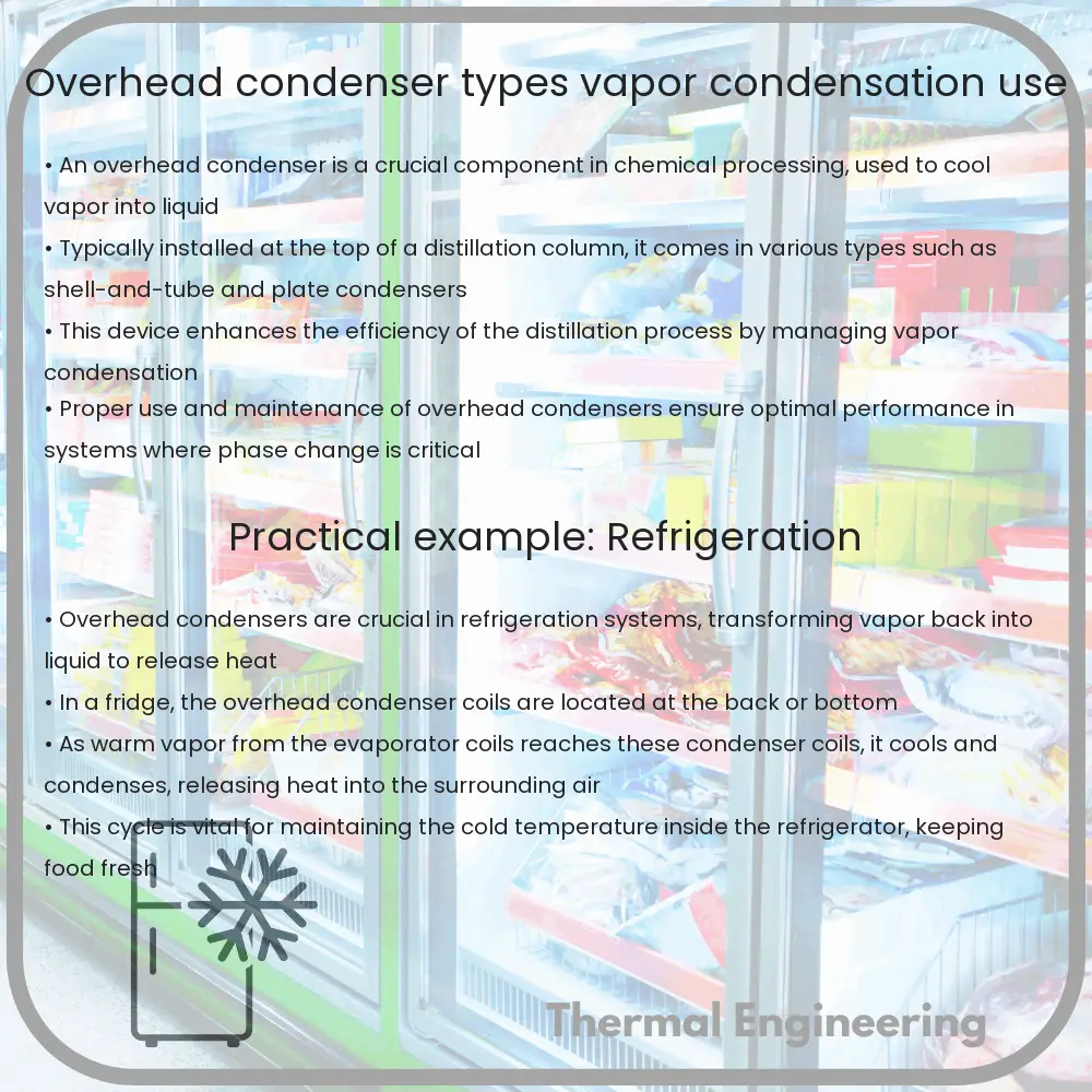
Overhead Condenser | Types, Vapor Condensation, Use

Learn about overhead condensers, vital for distillation in chemical industries, encompassing types, mechanisms, and applications.

Overhead Condenser | Types, Vapor Condensation, Use

Understanding Overhead Condensers

An overhead condenser is a crucial component widely used in chemical and petrochemical industries, especially in distillation columns. This type of condenser is typically mounted at the top of a distillation column where it serves to cool and condense vapor back into liquid. The functionality and efficiency of overhead condensers play a vital role in the distillation process, impacting both the purity of the product and the energy consumption of the unit.

Types of Overhead Condensers

Overhead condensers can be broadly categorized into two main types based on their design and function:

  1. Shell and Tube Condensers: This is the most common type of condenser used in industrial applications. It consists of a series of tubes encased in a larger shell. The vapor flows through the shell side and cools when it comes into contact with the cold tubes, which are typically cooled by water or another coolant.
  2. Plate Condensers: Plate condensers use a series of metal plates instead of tubes. The vapor passes through the spaces between these closely spaced plates, and cooling water flowing through alternate plates removes heat from the vapor. This design is more compact and can achieve higher heat transfer efficiency compared to shell and tube condensers.

Vapor Condensation Mechanisms

In overhead condensers, vapor condensation occurs primarily through two mechanisms:

  • Total Condensation: Here, all the vapor entering the condenser is converted into liquid. This method is typically employed in systems where the whole distillate needs to be collected as a liquid.
  • Partial Condensation: This method involves condensing only a part of the vapor, while the rest remains in gaseous form. Partial condensation is used in applications where non-condensable gases need to be separated from the vapor mix.

Use of Overhead Condensers

Overhead condensers are predominantly used in distillation processes to condense the vapor back into liquid form at the top of the distillation column. The condensed liquid, often referred to as the distillate, can be either collected as a product or returned to the column as reflux. This reflux helps to control the concentration of the components in the final product. Overhead condensers are thus crucial for achieving the desired efficiency and effectiveness of the distillation process. Their design and operational parameters are typically tailored to the specific requirements of the process, including the type of mixture being separated and the desired purity of the final products.

Conclusion

Overhead condensers are a fundamental component in many engineering systems, particularly in chemical processing. Through efficient condensation of vapors, they assure the continual operation of distillation columns while enhancing energy efficiency and product purity. With advancements in technology, modern condensers are becoming more efficient and reliable, paving the way for more sustainable industrial operations. Understanding the types of condensers, mechanisms of vapor condensation, and their applications in various fields is essential for any engineering professional involved in the design or operation of chemical separation processes.

Thermal effects on material properties

Learn how temperature changes affect material properties such as thermal expansion, conductivity, and strength in various applications.

Thermal effects on material properties

Understanding Thermal Effects on Material Properties

When materials are subjected to changes in temperature, their properties can alter dramatically. This concept is crucial in engineering and physics, as it influences the selection of materials for specific applications, particularly where temperature variations are significant. In this article, we’ll explore how temperature impacts various material properties including thermal expansion, strength, and conductivity.

Thermal Expansion

Thermal expansion is the tendency of matter to change its shape, area, and volume in response to a change in temperature. Most materials expand when heated and contract when cooled. The amount by which a material expands or contracts can be quantified by its coefficient of thermal expansion (CTE), which varies among different materials.

  • Metals: Generally, metals have high thermal expansion coefficients. Aluminum, for instance, expands considerably with temperature increase, which must be considered when using it in applications like bridge construction or aircraft design.
  • Polymers: Polymers can have a wide range of thermal expansions, often higher than metals, influenced by their structure and composition.
  • Ceramics: Typically have lower thermal expansions, which make them valuable in high-temperature applications but also more susceptible to thermal shock.

The mathematical description of thermal expansion in one dimension can be expressed as:

Lt = L0 (1 + αΔT)

Here, Lt is the final length, L0 is the initial length, α is the coefficient of thermal expansion, and ΔT is the change in temperature.

Thermal Conductivity

Thermal conductivity is a material’s ability to conduct heat. It plays a crucial role in applications where heat transfer is essential, such as in heat exchangers, thermal insulators, and electronic devices.

  • Metals: Typically have high thermal conductivity due to the free movement of electrons. Copper and silver are excellent examples of high thermal conductivity materials.
  • Polymers: Have low thermal conductivities, which make them good thermal insulators.
  • Ceramics: Vary greatly, but many are good at resisting heat flow as well as being resistant to high temperatures.

Change in Mechanical Strength

The strength of materials can also be affected by temperature changes. Typically, materials lose strength at higher temperatures.

  • Metals: Their strength usually decreases with an increase in temperature. For instance, steel loses much of its strength at high temperatures, which is a critical consideration in structures exposed to fire conditions.
  • Polymers: Heat can rapidly degrade polymers, affecting their usefulness in applications such as high-temperature environments.
  • Ceramics: Tend to maintain their strength up to very high temperatures, surpassing metals and polymers, which makes them indispensable in high-temperature applications.

In conclusion, understanding thermal effects on material properties is essential in engineering. This knowledge determines material selection and design criteria in environments where temperature conditions are a significant concern. As engineers and designers continue to push the boundaries of technology and construction, mastering these principles will become even more crucial.

Shell and Coil Heat Exchanger | Design, Process Cooling

Learn about shell and coil heat exchangers, their design, applications, and why they are essential in industrial cooling systems.

Shell and Coil Heat Exchanger | Design, Process Cooling

Understanding Shell and Coil Heat Exchangers

Shell and Coil Heat Exchangers are a specific type of heat exchanger used extensively in various industrial applications, especially for process cooling. This article will explore the design and functionality of shell and coil heat exchangers, illustrating how they are utilized within engineering systems.

Design of Shell and Coil Heat Exchangers

The shell and coil heat exchanger consists of a large shell and a helical coil that is immersed in the fluid. The coil is usually made from conducting materials such as copper or stainless steel, which allows efficient heat transfer. The primary components of this heat exchanger include the shell, the coil, and the inlet and outlet ports, which manage the flow of fluids in and out of the exchanger.

  • Shell: This is the outer part of the heat exchanger and holds the secondary fluid which surrounds the coil.
  • Coil: A helical coil that carries the primary fluid to be cooled or heated. The design of the coil enhances the surface area, which in turn increases heat transfer efficiency.
  • Inlet and Outlet Ports: These are used for the entry and exit of fluids. The design and positioning of these ports are crucial for optimizing the flow dynamics and subsequently the heat exchange efficiency.

Process Cooling with Shell and Coil Heat Exchangers

The process of cooling in shell and coil heat exchangers involves transferring heat from the process fluid within the coil to the secondary fluid in the shell. The efficiency of this process depends on several factors:

  1. Thermal conductivity of the coil material: Materials with higher thermal conductivity, such as copper, are typically used to make the coils more effective at transferring heat.
  2. Flow configuration: The flow of the fluids can be configured as counterflow or parallel flow, with counterflow generally providing better heat transfer efficiency.
  3. Fluid properties: The specific heat capacity, viscosity, and flow rate of the fluids also affect the efficiency of the heat transfer.

The heat transfer equation can be expressed as Q = U * A * ΔTLMTD, where:

  • Q is the rate of heat transfer
  • U is the overall heat transfer coefficient
  • A is the surface area for heat transfer
  • ΔTLMTD is the logarithmic mean temperature difference, calculated based on inlet and outlet temperatures of the fluids.

Applications and Advantages

Shell and coil heat exchangers are used in various sectors, including chemical processing, pharmaceuticals, HVAC, and food and beverage industries. They are preferred for their compact size and efficiency in transferring heat. Additionally, their simple design makes them easy to maintain and less prone to fouling compared to other types of heat exchangers.

The key advantages include:

  • High heat transfer efficiency due to the helical structure of the coils.
  • Compact size, which is beneficial in applications where space is a constraint.
  • Robustness and durability provided by the choice of materials.
  • Lower maintenance costs and easy to clean.

Conclusion

Shell and coil heat exchangers are vital components in many industrial cooling systems, providing high efficiency and durability. Their design and operation allow for effective heat transfer in compact spaces, making them ideally suited for a variety of cooling processes in several sectors. Understanding these exchangers can aid in optimizing their use and improving overall system efficacies in industrial applications.

Positive Displacement Blower | Mechanism, Pneumatic Conveying

Learn about positive displacement blowers, essential for consistent air volume in various industrial applications.

Positive Displacement Blower | Mechanism, Pneumatic Conveying

Understanding Positive Displacement Blowers

Positive displacement blowers are crucial in various industrial applications requiring consistent air or gas volume displacement. They differ from other types of fans or blowers mainly because they deliver a fixed volume of air with each revolution, achieving this through a mechanism that traps air into pockets surrounding the casing. This mechanism makes them incredibly useful for applications involving pneumatic conveying systems, wastewater treatment, and other processes needing precise air or gas management.

Mechanism of Positive Displacement Blowers

The core component of a positive displacement blower is its rotor configuration, which consists of two or three lobed rotors that rotate in opposite directions. The design and number of lobes can vary, but the general principle remains the same. Each rotor has a precise, fixed geometry that allows it to trap a specific volume of air or gas between the rotor and the blower casing as it rotates. This trapped volume is then carried from the intake side to the discharge side of the blower, where it is expelled at a higher pressure than when it was taken in.

  • The air is drawn into the blower as the rotor lobes unmesh at the intake side.
  • The rotors mesh together again to isolate the volume of air.
  • The air is carried around the case and is compressed gradually as the space between the lobes decreases.
  • Finally, the air is pushed out at the discharge side as the lobes mesh completely in the discharge area.

The tight sealing between the lobes and the casing ensures minimal leakage and hence a highly efficient operation. The level of pressure increase (also known as pressure ratio) and the volumetric efficiency of the blower are impacted by factors such as the speed of operation and the clearance between the rotors and the casing.

Pneumatic Conveying with Positive Displacement Blowers

Pneumatic conveying is a method used extensively in bulk material handling by using the flow of air or gas to transport materials through pipes. Positive displacement blowers play a pivotal role in this process, especially in systems requiring sustained and reliable air flow.

The two main types of pneumatic conveying systems that utilize positive displacement blowers are:

  1. Dilute Phase Conveying: This method involves transporting materials at a high velocity through the conveying line. The integrity and uniformity of the air flow provided by positive displacement blowers allow for the continuous movement of materials, which can be in the form of powders, granules, or pellets.
  2. Dense Phase Conveying: In this method, materials are moved at a lower velocity, resulting in a more concentrated form of the product moving through the line. Positive displacement blowers can provide the exact and controlled air volumes required for such a system, minimizing wear and tear on the conveying line and reducing power consumption.

Positive displacement blowers, with their ability to deliver a constant air volume despite changes in pressure, are therefore ideal for both types of pneumatic conveying systems.

Benefits and Applications

Positive displacement blowers are essential in applications beyond just pneumatic conveying. Their precise control of air flow and pressure makes them suitable for applications such as air scouring in water treatment plants, fluidization of products in manufacturing processes, and operations in the cement and mining industries. They are favored for their robustness, efficiency, and reliability in delivering consistent airflow necessary for various critical industrial operations.

In conclusion, understanding the mechanism and applications of positive displacement blowers highlights their importance in modern engineering and industrial processes. By providing controlled and consistent air displacement, these blowers ensure efficient, reliable, and effective operations across a range of industries.

Cyclonic Separator | Working, Gas-Solid Particle Removal

Learn how cyclonic separators efficiently remove particulates from gas streams, crucial in environmental and industrial applications.

Cyclonic Separator | Working, Gas-Solid Particle Removal

Understanding Cyclonic Separators

Cyclonic separators are widely used in various engineering fields, particularly in environmental engineering, chemical processing, and the automotive industry, where they serve the crucial role of separating solid particles or liquid droplets from gas streams. Their ability to remove particulates from air or gases makes them essential components in reducing air pollution and in protecting sensitive machinery components in processing plants.

How Cyclonic Separators Work

The principle behind cyclonic separation is relatively straightforward. A cyclonic separator employs rotational effects and gravity to separate mixtures of solids and fluids. The basic process occurs as follows:

  1. Gas Entry: The gas containing solid particles enters the separator through an inlet at the top, directed into a spiral trajectory.
  2. Creation of Vortex: As the gas spirals downward, the rotational effects create a vortex. Due to the centrifugal forces, the heavier solid particles are pushed out towards the wall of the cylinder.
  3. Particle Collection: The particles gain momentum as they travel in the cylinder, descend due to gravity, and ultimately collect at the bottom of the separator in a collection area, often referred to as a hopper.
  4. Gas Exit: The clean gas, which is relatively free of particles, moves in an upward, inner vortex towards an outlet positioned at the top of the cylinder.

This method is particularly effective for removing particles greater than about 5 microns in diameter. The efficiency of a cyclonic separator can vary based on several factors, including particle size and density, gas viscosity, and the diameter of the cyclone itself.

Mathematical Aspect of Particle Removal

The efficiency of particle removal in a cyclonic separator can be estimated by dimensional analysis using the Stokes number (Stk), a dimensionless number that describes the behavior of particles in a flowing stream. It is given by the formula:

\[ Stk = \frac{u_{in} \times d_p \times \rho_p}{18 \mu \times L} \]

where:

  • uin is the inlet velocity of the gas,
  • dp is the particle diameter,
  • ρp is the particle density,
  • μ is the viscosity of the gas,
  • L is the characteristic dimension of the cyclone, typically the cyclone diameter.

The higher the Stokes number, the more efficient the cyclone is at capturing the particles, leading to improved separation performance.

Applications of Cyclonic Separators

In practical applications, cyclonic separators are used in several industries and situations:

  • Industrial Exhausts: Removing particulate matter from industrial exhaust streams to prevent air pollution.
  • Oil Refineries: Separating particles and droplets from gases in petroleum refineries.
  • Manufacturing: Protecting sensitive machinery from abrasive particles that could cause wear and tear.
  • Aerospace: Used in jet engines to prevent particulate matter from entering combustion chambers.

Overall, cyclonic separators provide a robust and cost-effective method to remove particles and droplets from gas streams, contributing significantly to operations across many fields. Their simplicity, effectiveness, and ability to operate without moving parts or requiring external power sources help explain their widespread usage in industry.

Membrane Bioreactor | Technology, Treatment Efficiency

Learn about membrane bioreactors (MBR), an advanced wastewater treatment technology combining biological processes and membrane filtration.

Membrane Bioreactor | Technology, Treatment Efficiency

What is a Membrane Bioreactor?

A membrane bioreactor (MBR) is an advanced technology used in wastewater treatment. Combining conventional biological degradation processes with membrane filtration, MBR systems provide an efficient solution for wastewater treatment and reclamation. This technology helps in producing high-quality effluent which is suitable for a variety of reuse applications, including irrigation and industrial processes.

Components and Technology

Typically, a membrane bioreactor system consists of two main components:

  • Biological Reactor: This is where the biological degradation of organic matter occurs. Microorganisms in the reactor degrade pollutants dissolved in wastewater.
  • Membrane Unit: Following biological treatment, the wastewater is passed through a membrane filtration unit. This unit can be made up of microfiltration or ultrafiltration membranes that serve to separate solids, bacteria, and viruses from the water, producing a clarified effluent.

The membranes can be submerged directly in the biological reactor or placed in a separate tank where the treated water from the reactor is pumped through the membranes. Such configurations are known as submerged and side-stream MBR systems, respectively.

Treatment Efficiency

Membrane bioreactors are known for their high treatment efficiency, addressing both organic and nutrient removal. The key aspects of this efficiency include:

  • High-Quality Effluent: MBR systems typically produce effluent of high clarity and low bacterial content, which can often meet the stringent quality standards required for various reuse and discharge scenarios.
  • Small Footprint: Compared to conventional wastewater treatment systems, MBRs require less space due to their enhanced biomass concentration and the elimination of secondary clarifiers.
  • Flexibility and Modularity: MBR systems can easily be scaled up or down by adding or removing membrane units. This flexibility makes it a favored choice for areas where space is limited or population growth is anticipated.
  • Reduced Sludge Production: MBR processes result in less sludge compared to conventional systems. The high-quality treatment process also extends the intervals between desludging operations.

Challenges and Considerations

Despite many advantages, there are several challenges associated with membrane bioreactors:

  • Membrane Fouling: This is a major operational issue where particles, bacteria, and other substances cake on the membrane surface, reducing its efficiency and increasing maintenance needs.
  • Higher Energy Demand: MBR systems generally consume more energy compared to traditional wastewater treatment systems, primarily due to the energy used in pumping water through the membranes.
  • Cost: The initial capital and operating costs of MBRs can be higher due to the complexity of the technology and the need for frequent maintenance and replacement of membranes.

In conclusion, while the membrane bioreactor technology is highly effective for water treatment, it requires careful consideration regarding its operational and economic feasibility based on the specific requirements and constraints of the application it is intended for.

Future of Membrane Bioreactors

Advancements in membrane technology, such as the development of more fouling-resistant membranes and energy-efficient operation strategies, continue to enhance the attractiveness and feasibility of MBR systems. The ongoing research and improvements aim to lower costs and reduce the ecological footprint of these systems, making them an increasingly viable option for sustainable wastewater management around the globe.

Rotary Evaporator | Principle, Solvent Recovery, Lab Use

Explore the functionality and applications of rotary evaporators, essential lab equipment for efficient solvent removal in chemistry and pharmaceuticals.

Rotary Evaporator | Principle, Solvent Recovery, Lab Use

Introduction to Rotary Evaporators

A rotary evaporator, often simply called a rotavap, is a device commonly used in chemical laboratories for the efficient and gentle removal of solvents from samples by evaporation. Since its invention by Lyman C. Craig in 1950, the rotary evaporator has become a staple in labs around the world, particularly those involved in the fields of organic chemistry and pharmaceuticals.

Principle of Operation

At its core, a rotary evaporator works by increasing the rate of evaporation of a solvent by reducing the pressure in the container holding the solvent, increasing the surface area of the solvent, and carefully controlling the temperature. These factors work together to speed up the process of solvent elimination, which is crucial when working with sensitive materials that might degrade under high temperatures.

  • Pressure Reduction: A vacuum pump decreases the pressure within the rotating flask. Lower pressure reduces the boiling point of the solvent, allowing it to evaporate at lower temperatures.
  • Increased Surface Area: The flask containing the solvent is rotated, which creates a thin film of liquid over the surface of the flask, thereby increasing the surface area and helping to speed up evaporation.
  • Temperature Control: The solvent is heated in a water or oil bath while being evaporated. The temperature of the bath is typically much lower than the solvent’s boiling point at standard pressure, which is beneficial for temperature-sensitive materials.

Solvent Recovery

One of the main advantages of using a rotary evaporator is the ability to recover solvents. The process not only removes solvents from a sample efficiently but also captures and condenses these solvents so they can be recycled or disposed of in a more controlled manner. This is achieved through a cooling condenser, where the evaporated solvent vapours are turned back into liquid form, collected in a receiving flask.

Laboratory Uses

In a laboratory setting, rotary evaporators have a multitude of uses, including but not limited to the concentration of solutions, the drying of powders, and the extraction of solvents. Here’s how they are typically employed:

  1. Sample Concentration: Removing solvents from a solution through evaporation to increase the concentration of the sample.
  2. Reagent Recycling: Solvents like diethyl ether or dichloromethane can be recovered and reused, thereby reducing waste and costs.
  3. Solvent Extraction: Rotary evaporators can also facilitate the removal of solvent from mixtures, which is common in chemical synthesis and pharmaceutical applications.
  4. Powder Drying: After solvent removal, residual solids can be dried using a rotary evaporator, ensuring minimal degradation compared to other drying methods which might use higher temperatures.

Understanding the operational principles of rotary evaporators enhances their efficiency in the laboratory. By mastering these, scientists and technicians can optimize procedures such as controlling the rate of rotation and the temperature settings appropriate for different solvents and materials.

Conclusion

Rotary evaporators are crucial devices in the chemistry lab, known for their efficiency and versatility in solvent removal and recovery. Their importance stretches across various sectors in science, particularly in organic chemistry and pharmaceutical applications, making an understanding of their function and use essential for modern laboratory operations.

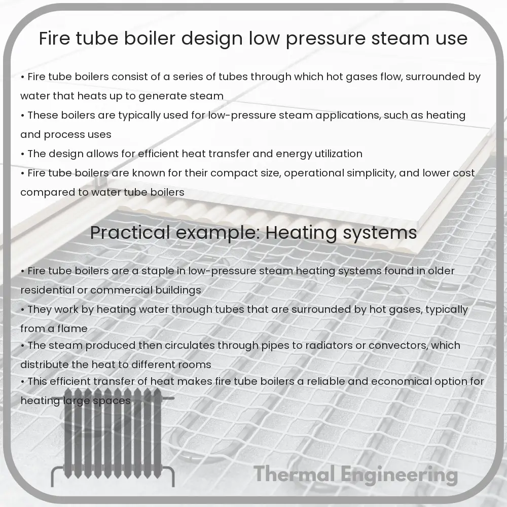
Fire Tube Boiler | Design, Low-Pressure Steam Use

Learn about the design, operation, and applications of Fire Tube Boilers, a fundamental boiler type used since the 18th century.

Fire Tube Boiler | Design, Low-Pressure Steam Use

Introduction to Fire Tube Boilers

Fire tube boilers are a type of boiler in which hot gases from a fire pass through one or more tubes running through a sealed container of water. The heat of the gases is transferred through the walls of the tubes by thermal conduction, heating the water and ultimately creating steam. These boilers are one of the oldest types of boilers and have been in use since the 18th century.

Design of Fire Tube Boilers

The design of fire tube boilers involves a cylindrical shell, closed at both ends, with a horizontal set of tubes that passes through the cylindrical shell. The fire itself is burned in a furnace that is an integral part of the boiler, but could also be separate, depending on the boiler configuration. Here’s how these components are typically arranged:

  • Shell: This is the outer cylindrical portion of the boiler, enclosing the water, steam, and the tubes through which the hot gases pass.
  • Tubes: A large number of small tubes running through the boiler help in the heat transfer process. The hot gases pass through these tubes, and the water surrounds these tubes.
  • Furnace/Firebox: This is where the fuel is burned to generate heat. The resulting hot gases are then directed into the tubes.
  • Smokestack: After the gases have passed through the tubes, they are expelled out of the boiler system through the smokestack or chimney.
  • Fire Door: It allows technicians to access the firebox for maintenance and fuel loading.

Operation of Fire Tube Boilers

The operation of a fire tube boiler is relatively simple. Fuel, often coal, wood, oil, or gas, is burned in the firebox, producing hot gases. These gases flow through the tubes, surrounded by water in the main body of the boiler. Heat from the gases passes into the water, turning it into steam.

Advantages and Disadvantages of Fire Tube Boiler

  • Advantages:
    • Simple construction makes them cheaper to manufacture and easier to maintain.
    • They have a compact shape and small water volume, which means they can produce steam at a faster rate.
    • Operational simplicity and reliability.
  • Disadvantages:
    • Lower efficiency in generating high pressure steam.
    • Not suitable for high power applications in which large volumes of steam are required.
    • Higher risk of explosion due to the large amount of water contained within the boiler shell.

Applications of Low-Pressure Steam in Fire Tube Boilers

Low-pressure steam generated by fire tube boilers is predominantly used in a variety of applications:

  • Heating applications in buildings and facilities.
  • Provision of steam for industrial processes at lower pressures.
  • Culinary uses such as steam for baking and cooking.
  • Steam for cleaning and sterilization processes.

Conclusion

While fire tube boilers are not suitable for high power or high pressure applications, their simplicity and cost-effectiveness make them a valuable tool for many heating tasks and low-pressure steam needs. With their extensive usage in non-power generation sectors, they remain a crucial component in many industrial and commercial setups.