Facebook Instagram Youtube Twitter

Magnetic Flow Meter | Electromagnetic, Wastewater Treat

Learn about magnetic flow meters, essential tools for measuring fluid flow in pipes using electromagnetic principles, ideal for impure liquids like wastewater.

Magnetic Flow Meter | Electromagnetic, Wastewater Treat

Understanding Magnetic Flow Meters

Magnetic flow meters, often referred to as mag meters or electromagnetic flow meters, are devices used to measure the flow rate of a fluid in a pipe. They utilize the principles of electromagnetism to produce a result that does not depend on moving parts, making them ideal for measuring the flow of liquids that contain impurities such as wastewater.

How Do Magnetic Flow Meters Work?

Magnetic flow meters operate based on Faraday’s Law of Electromagnetic Induction, which states that a voltage will be induced when a conductor moves through a magnetic field. In the context of a magnetic flow meter, the liquid acts as the conductor. As the fluid flows through the meter’s magnetic field, a voltage is induced. This voltage is directly proportional to the velocity of the flowing fluid and can therefore be used to calculate its flow rate.

The basic formula derived from Faraday’s Law for a magnetic flow meter is:

E = k * B * D * V

  • E is the voltage generated.
  • k is a constant depending on the characteristics of the meter.
  • B is the magnetic field strength.
  • D is the diameter of the pipe.
  • V is the average velocity of the fluid flow.

By measuring the induced voltage (E) and knowing the other factors, the flow rate of the fluid can be calculated.

Applications in Wastewater Treatment

Magnetic flow meters are particularly advantageous in wastewater treatment facilities due to their ability to handle dirty liquids that may contain solids, fibers, and other debris. These qualities make them suitable for various applications within the facility, including:

  • Measuring the inflow and outflow of wastewater.
  • Regulating dosages of treatment chemicals.
  • Monitoring reclaimed water.

Advantages of Using Magnetic Flow Meters

Magnetic flow meters offer several advantages over other types of flow meters:

  • Non-invasive Measurement: Since the measurement does not depend on moving parts, there is minimal wear and tear, making mag meters highly durable and low maintenance.
  • Accuracy: They provide highly accurate flow measurement, especially useful in applications involving corrosive liquids or slurries.
  • Versatility: Capable of measuring almost any liquid that conducts electricity, including harsh industrial fluids and wastewater.

Limitations

Despite their numerous advantages, magnetic flow meters also have some limitations:

  • They can only be used with conductive liquids, and their effectiveness decreases with decreasing conductivity.
  • In very low flow conditions, their accuracy might be compromised.
  • External magnetic fields can interfere with the measurement.

Conclusion

Magnetic flow meters are an essential instrument in engineering, particularly in industries managing fluids that contain multiple impurities such as wastewater treatment. Their principle of operation based on Faraday’s Law, combined with their robust and non-invasive nature, makes them ideal for such environments. Understanding how these meters work and their application scope can significantly benefit professionals in the field of fluid mechanics and wastewater management.

Thermal Flow Switch | Temp Detection, Flow Control

Learn how thermal flow switches monitor and manage fluid flow in various systems, ensuring operational safety and efficiency.

Thermal Flow Switch | Temp Detection, Flow Control

Understanding Thermal Flow Switches: Temperature Detection and Flow Control

Thermal flow switches are crucial components used in various applications to monitor and manage the flow of liquids and gases. This device operates based on changes in heat transfer in a fluid medium, making it a valuable tool for ensuring operational safety and efficiency in systems like HVAC, process industries, and equipment cooling.

How Thermal Flow Switches Work

The fundamental principle behind thermal flow switches is relatively straightforward. It involves two temperature sensors integrated into the switch. One sensor measures the temperature of the fluid at its ambient state, serving as a reference, while the other is heated and measures the temperature change due to the flow of the fluid. The difference in temperature between these two sensors helps determine the flow rate.

When there is no flow or the flow is below a preset threshold, the temperature difference between the two sensors remains relatively high due to the reduced cooling effect on the heated sensor. As flow increases, the fluid carries away more heat from the heated sensor, reducing the temperature difference. The switch is calibrated to respond to specific temperature differences, triggering an action when a particular flow rate is detected or not detected.

Key Components and Design

  • Temperature Sensors: Typically employ resistance temperature detectors (RTDs) or thermistors providing high accuracy.
  • Heating Element: Heats the active sensor to create a temperature differential necessary for operation.
  • Electronic Circuit: Processes the signals from the temperature sensors and outputs a control signal (often a relay) based on predetermined settings.
  • Housing: Constructed from materials compatible with the fluid to ensure durability and prevent corrosion.

Applications of Thermal Flow Switches

  • Industrial processes: Monitor and control the flow of coolants, lubricants, or other process fluids.
  • HVAC Systems: Ensure the proper flow of water and other fluids in heating and cooling systems.
  • Water Treatment: Detect changes in water flow to prevent equipment from running dry, which could lead to damage.
  • Safety Systems: Used in fire suppression systems to ensure coolant or suppression materials are flowing when needed.

Advantages and Limitations

Thermal flow switches offer several advantages, including simplicity, reliability, and their effectiveness in different fluid types without requiring significant modifications. However, their performance can be influenced by factors such as changes in fluid viscosity, temperature, and the presence of particulates in the fluid, which might require regular maintenance and calibration to ensure accuracy.

Conclusion

Thermal flow switches are essential tools for many engineering applications, providing critical monitoring and control for fluid flows. Understanding how they function, their applications, and limitations are vital for selecting the right switch for a specific need, ensuring that systems operate safely and efficiently.

Pneumatic Actuator | Valve Control, Automation

Learn how pneumatic actuators facilitate valve control and automation in various industries through the use of compressed air.

Pneumatic Actuator | Valve Control, Automation

Understanding Pneumatic Actuators: Essentials of Valve Control and Automation

Pneumatic actuators are a vital component in the field of automation and control engineering. These devices convert the energy of compressed air into mechanical motion. This type of actuator is particularly prevalent in the automation of valve operations, providing efficient and reliable means to control the flow of fluids in various industrial processes.

How Pneumatic Actuators Work

Pneumatic actuators operate on a simple principle: the conversion of energy from compressed air into mechanical motion. This motion can either be linear or rotary, depending on the design of the actuator. In the context of valve control, actuators typically use this motion to open or close valves, modulating the flow of gases or liquids through pipelines.

There are two main types of pneumatic actuators used in valve automation:

  • Rotary Actuators: These actuators turn a shaft to rotate the valve between open and closed positions, typically used with ball, plug, and butterfly valves.
  • Linear Actuators: These create a straight line motion to slide valve components for opening or closing, commonly used with gate and globe valves.

Components of a Pneumatic Actuator

A standard pneumatic actuator consists of several key components:

  • Body: The frame or casing that houses the other components of the actuator.
  • Piston: Moves within the cylinder under air pressure, creating motion to actuate the valve.
  • Spring: In spring-return actuators, the spring moves the piston back to its original position once air pressure is released.
  • Ports: Entry and exit points for compressed air that control the movement of the piston.

The Role of Compressed Air in Actuation

The use of compressed air is what sets pneumatic actuators apart from other types, such as hydraulic or electric actuators. Compressed air is ideal for use in many industrial environments due to its readiness and safety. Typically, air pressures used range from 20 to 120 psi (pounds per square inch), which are safe yet effective for robust industrial operations. The pneumatic system’s simplicity allows for lower maintenance and cost-effective solutions in valve automation.

Advantages of Using Pneumatic Actuators

  • Speed: Pneumatic actuators provide rapid response and quick movement of valve components.
  • Reliability: With fewer moving parts and minimal requirement for lubrication, these actuators are highly reliable and have a long service life.
  • Safety: Being powered by air, these systems don’t risk leaks of hazardous fluids and are preferred in explosive or flammable environments.
  • Cost-effectiveness: Generally, pneumatic systems are less expensive to install and maintain compared to their hydraulic and electric counterparts.

Applications in Industry

Pneumatic actuators are used extensively across various industries. Some common applications include:

  • Water treatment and distribution systems
  • Chemical and pharmaceutical manufacturing
  • Oil and gas industries
  • Food and beverage processing

They are particularly valued in industries where rapid and safe valve control is essential for efficient and smooth operations.

Challenges and Considerations

Despite their many benefits, pneumatic actuators do have limitations. Air supply must be clean and dry to avoid equipment degradation or failure. Additionally, temperature extremes can affect performance, and considerations must be taken for systems that require precise control over position, as compressed air systems can be slightly less precise than electric ones.

In conclusion, pneumatic actuators play a crucial role in automation and control processes in many industries. By understanding their operation, components, and applications, engineers and technicians can better optimize these systems for efficiency and reliability.

Hydraulic Accumulator | Storage, Shock Absorption

Learn how hydraulic accumulators function in systems, their types, and applications in various industries to enhance efficiency and safety.

Hydraulic Accumulator | Storage, Shock Absorption

Introduction to Hydraulic Accumulators

A hydraulic accumulator is an essential component used in hydraulic systems to store pressurized hydraulic fluid. Primarily, it serves two critical functions: energy storage and shock absorption. This versatility makes accumulators indispensable in a variety of hydraulic applications ranging from mobile machinery to industrial settings.

How Hydraulic Accumulators Work

At its core, a hydraulic accumulator is a pressure storage reservoir in which a non-compressible hydraulic fluid is held under pressure by an external source. This external source can be a spring, a raised weight, or a compressed gas. The most common type of accumulator is the gas-charged bladder or piston type.

In these systems, when hydraulic fluid from the pump is forced into the accumulator, the gas (usually nitrogen) is compressed. When the pressure from the pump drops or the system needs additional fluid, the pressurized gas expands, pushing the stored fluid back into the hydraulic circuit.

Applications of Hydraulic Accumulators

  • Energy Storage: Accumulators can store energy when the demand is low and release it during a peak demand period without requiring additional power input. This helps in smoothing out the demand on the system, leading to more efficient energy use.
  • Shock Absorption: Hydraulic accumulators are excellent for absorbing shock caused by sudden changes in hydraulic pressure. This feature is critical in systems where shock and vibrations can cause damage or lead to system failure, such as in industrial machining or in heavy machinery operations.
  • Pulse Dampening: Similar to shock absorption, pulse dampening smooths out pulses within the hydraulic fluid, ensuring a steady flow rate and pressure in sensitive equipment.
  • Leak Compensation: In systems where small leaks are inevitable, accumulators help maintain pressure by compensating for lost fluid, thus ensuring uninterrupted operation of the hydraulic system.
  • Emergency Power: In case of power loss, an accumulator can provide enough hydraulic power for the system to shut down safely or maintain critical functions temporarily.

Types of Hydraulic Accumulators

  1. Bladder Accumulator: Features a rubber bladder inside a steel shell. Hydraulic fluid compresses the nitrogen in the bladder to store energy.
  2. Piston Accumulator: Uses a piston to separate the hydraulic fluid from the compressed gas. Suitable for larger volumes and higher flow rates.
  3. Diaphragm Accumulator: Similar to the bladder type but uses a diaphragm rather than a rubber bladder, offering simpler construction and maintenance.

Considerations for Using Hydraulic Accumulators

Selecting the right type of accumulator depends on several factors including system pressure, fluid volume, and the specific application needs. Safety is also a critical factor, as the stored energy in accumulators can be hazardous. Regular maintenance checks, such as inspecting for leaks and pressure integrity, are imperative to ensure safe and efficient operation.

Conclusion

Hydraulic accumulators play a vital role in enhancing the efficiency and safety of hydraulic systems. By understanding the various types of accumulators and their applications, engineers can design systems that are not only efficient but also robust and reliable. Whether in industrial machines, aerospace applications, or mobile machinery, hydraulic accumulators contribute significantly to the performance and reliability of hydraulic systems.

Check Valve | Backflow Prevention, Fluid Control

Learn about check valves, essential for preventing backflow and ensuring unidirectional fluid flow in piping systems.

Check Valve | Backflow Prevention, Fluid Control

Understanding Check Valves: Essentials of Backflow Prevention and Fluid Control

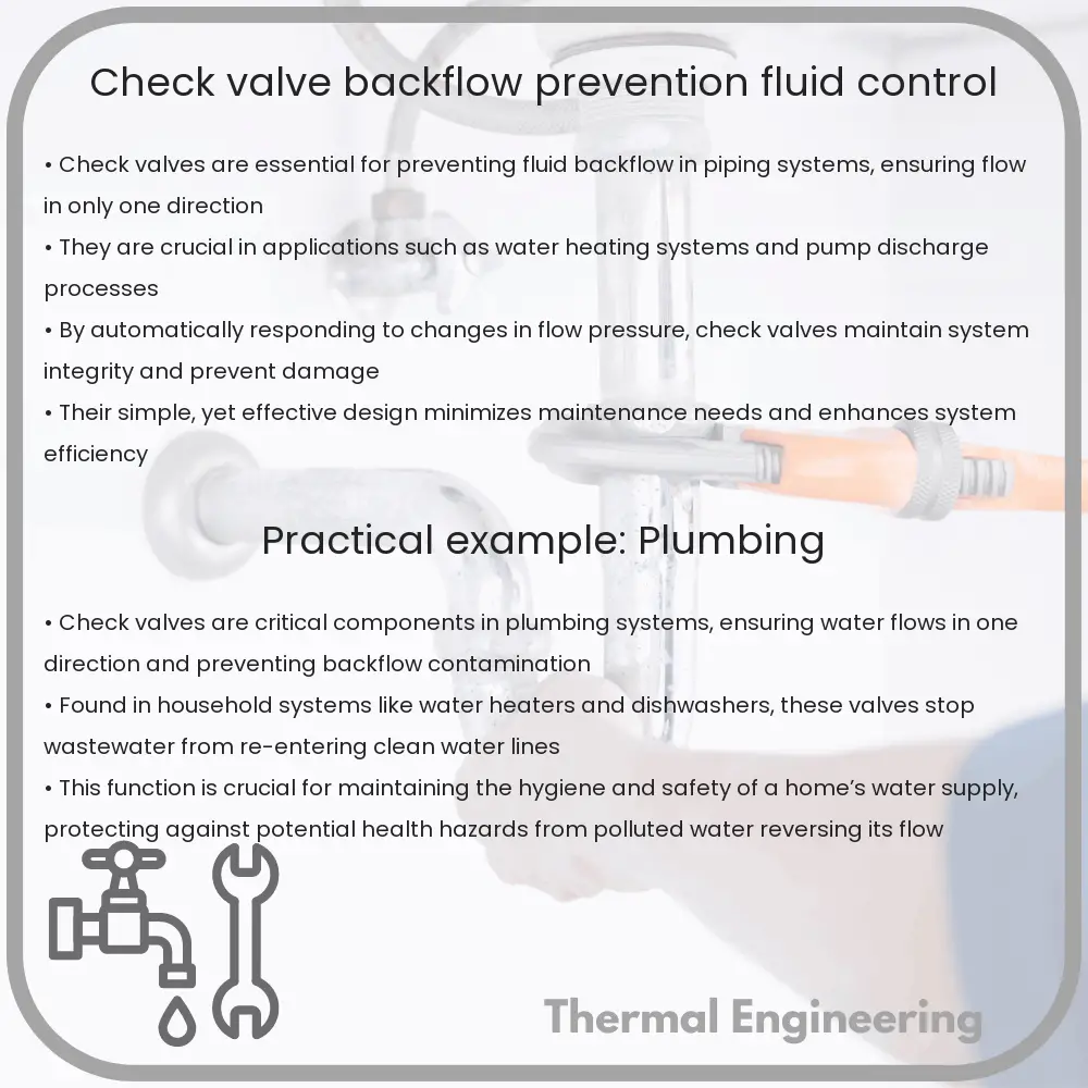
Check valves, also known as one-way valves or non-return valves, are a critical component in various piping systems. Their primary role is to prevent backflow and ensure fluid flows in only one direction. This simple yet vital function helps prevent potential problems such as water hammer, system contamination, and equipment damage. In this article, we’ll explore the basic principles, types, and applications of check valves in fluid control systems.

Basic Principles of Check Valves

At its core, a check valve allows fluid (liquid or gas) to flow through it in only one direction. The valve consists of a body, an entry port, an exit port, and a mechanism that allows the valve to open and close in response to flow pressure. When fluid enters the valve from the designated input direction, the pressure of the fluid opens the valve. Conversely, if fluid tries to flow in the opposite direction, the mechanism in the valve closes and blocks the flow.

Major Types of Check Valves

  • Swing Check Valves: These valves use a pivoting disc or door to allow or block flow. They are suitable for low-pressure drop applications and are often used in water supply systems.
  • Lift Check Valves: In these valves, fluid pressure lifts a ball or cone-shaped disc off its seat to allow flow. When the flow stops or reverses, gravity or a spring returns the disc to its seat, stopping the flow.
  • Wafer Check Valves: Known for their compact design, wafer check valves are placed between two flanges in a pipeline. They are typically lighter and smaller than swing check valves, making them ideal for systems with space constraints.
  • Duckbill Check Valves: Utilizing a flexible rubber material that forms a duckbill-shaped one-way entrance, these valves are commonly used in medical applications and sewage treatment systems.

Applications of Check Valves

Check valves are used in a variety of settings and industries to protect equipment and processes. The following are some key applications:

  1. Water and Sewage Systems: To prevent the reverse flow of contaminated water into the clean water supply.
  2. Pumping Systems: To prevent the backflow of water that could damage pumps and other equipment.
  3. Chemical and Power Plants: To control the flow of gases and liquids in various processes.
  4. Boilers: To prevent the reverse flow of steam and condensate.
  5. Load Holding: Hydraulic systems use check valves to hold loads and prevent reverse flow, which could lead to uncontrolled system movements.

Choosing the Right Check Valve

To ensure optimal performance and durability, it’s crucial to select the right type of check valve based on the specific requirements of the system, such as flow rate, pressure, and the nature of the fluid. Factors such as valve size, material compatibility (with the fluid), and pressure drop must also be considered. For instance, wafer check valves are preferred in tight spaces, while swing check valves are chosen for systems where low pressure drop is essential.

In conclusion, check valves play an indispensable role in many engineering systems, offering both protection and improved reliability. By understanding the basic types and applications, as well as the factors involved in selecting an appropriate check valve, engineers can design systems that are both efficient and safe.

Expansion Tank | Volume Compensation, Pressure Control

Learn about the function and design of expansion tanks, essential for pressure stability and system integrity in thermal and hydraulic systems.

Expansion Tank | Volume Compensation, Pressure Control

Understanding Expansion Tanks: Volume Compensation and Pressure Control in Engineering Systems

Expansion tanks are critical components in various mechanical systems where fluid volume tends to fluctuate due to temperature and pressure changes. Employed extensively in closed-loop heating and cooling systems, as well as in potable water applications, these tanks help maintain pressure stability and prevent system damage or failure. This article explores the principles behind expansion tanks and how they manage volume compensation and pressure control.

What is an Expansion Tank?

An expansion tank is a vessel designed to absorb the expansion and contraction of a fluid, typically water or an antifreeze solution, thereby maintaining a constant pressure within a heating or cooling system. The tank is divided into two sections by a rubber diaphragm. One side is connected to the system pipe work and contains the fluid, while the other side is filled with air or an inert gas.

How Do Expansion Tanks Work?

The primary function of an expansion tank is to compensate for the increase in volume and associated pressure rise in a system’s fluid due to temperature changes. As the temperature of the fluid increases, its volume expands. Without a mitigation strategy, this volume increase can lead to dangerously high pressures that could compromise system integrity. The expansion tank allows this extra volume a space to go, thereby reducing undue stress on the system.

Pressure Control via Expansion Tanks

The key to effective pressure control in an expansion tank is the pre-charge (initial gas pressure) of the air cushion, adjusted to the system’s static pressure. This pre-charge prevents the tank from being completely compressed at the normal operating pressure, which can cause the pressure to rise too high or drop too low, potentially leading to system failure.

Volume Calculation for Expansion Tanks

The volume of an expansion tank necessary to adequately serve a system is based on several factors, including the total volume of fluid, the temperature range the system will encounter, and the initial system pressure. The formula for calculating tank size is typically expressed as:

\[ V_t = \frac{V_s \cdot \beta \cdot (\Delta T)}{(P_1 – P_0)} \]

Where:

  • Vt: Volume of the expansion tank
  • Vs: Volume of the system
  • β: Volumetric expansion coefficient of the fluid
  • ΔT: Temperature change in degrees Celsius
  • P1: Maximum system pressure
  • P0: Initial (pre-charge) pressure of the expansion tank

Applications of Expansion Tanks

Expansion tanks are used in a variety of settings, including:

  • Residential and commercial heating systems
  • Cooling systems, including air conditioning and refrigeration units
  • Solar heating systems
  • Hydraulic applications in industrial processes

The proper functioning of these tanks is crucial for the longevity and efficiency of thermal and hydraulic systems. Regular maintenance checks, such as monitoring pressure levels and checking for leaks or membrane integrity, are essential for ensuring optimal performance.

Conclusion

Expansion tanks play a fundamental role in managing the dynamics of fluid expansion and maintaining the requisite pressure in closed-loop systems. By understanding the principles of volume compensation and pressure control, engineers can better design, utilize, and maintain these tanks to ensure system stability and durability. The ability of expansion tanks to adapt to varying conditions makes them an indispensable part of modern engineering systems.

Butterfly Valve | Quick Operation, Flow Regulation

Learn about butterfly valves, vital for regulating fluid flow in industrial applications, featuring simple design and rapid operation.

Butterfly Valve | Quick Operation, Flow Regulation

Introduction to Butterfly Valves

Butterfly valves are a type of flow control device, used to regulate or isolate the flow of a fluid. They consist of a rotating disc that pivots on an axis perpendicular to the flow in the pipe, similar to the operation of a butterfly’s wings, which is how they derive their name.

Why Use Butterfly Valves?

Butterfly valves are favored in many industrial applications because they are cost-effective, have a relatively simple construction, and provide quick operation with minimal effort. They are suitable for a wide range of fluids and can operate under varying pressure and temperature conditions.

Components of Butterfly Valves

  • Body: The main structure that holds all other components together and connects to the piping system.
  • Disk: The disk is the part that actually regulates the flow as it rotates within the body of the valve.
  • Stem: The stem connects the disk to an actuator or handle outside the valve body and transmits the motion to open or close the valve.
  • Seat: Usually made of rubber or other elastic materials, the seat provides a seal between the disk and the valve body.
  • Actuator: Can be manual, electric, hydraulic, or pneumatic, and is used to control the position of the disk.

Operating Principle

The operation of a butterfly valve is straightforward. When the valve handle or actuator is turned, the internal disc, which is mounted on a rod, rotates. A 90-degree rotation of the disc either completely opens or completely closes the valve. Intermediate positions allow for regulating the flow according to the angle of the disc.

Types of Butterfly Valves

  1. Zero Offset Butterfly Valve: The most common type, used for low-pressure and temperature applications.
  2. Double Offset Butterfly Valve: Also known as a high-performance butterfly valve, it is designed for higher pressure and temperature services.
  3. Triple Offset Butterfly Valve: Used for applications requiring tight shut-off, such as in high-pressure steam systems.

Advantages of Butterfly Valves

  • Compact and lightweight design.
  • Lower cost compared to other valve types, like ball valves.
  • Quick operation with low torque, easy to automate.
  • Minimal pressure drop when fully opened.

Applications

Butterfly valves are versatile and can be used in various sectors including water and wastewater treatment, fire protection, power generation, and chemical processing. They handle not only liquids but also gases and slurries. Their ability to throttle makes them particularly useful in flow regulation tasks.

Conclusions

Butterfly valves are an essential component in many piping systems allowing efficient control over the flow of fluids. Their simple mechanism, quick operation, and cost-effectiveness make them a preferable choice for many engineers and industry professionals.

Swirl Meter | Vortex Shedding, Flow Measurement

Learn about vortex shedding and swirl meters for accurate industrial flow measurement.

Swirl Meter | Vortex Shedding, Flow Measurement

Understanding Swirl Meters and Vortex Shedding for Flow Measurement

Flow measurement is a critical aspect in various engineering fields, including chemical processing, water management, and oil and gas industries. Among the different technologies employed for measuring flow rates, swirl meters and vortex shedding flow meters stand out for their accuracy and versatility. This article will delve into the principles of vortex shedding and the functionality of swirl meters, along with their applications.

What is Vortex Shedding?

Vortex shedding is a fluid dynamics phenomenon that occurs when a fluid such as water or air flows past a bluff (non-streamlined) body. The process of flow separation forms alternating vortices downstream of the body. These vortices, known as the Von Kármán vortex street, shed alternately from opposite sides of the body, creating a swirling flow pattern.

This phenomenon is characterized by oscillations in the pressure and velocity of the fluid, which can be captured and used to measure the flow rate. The frequency of these oscillations, known as the Strouhal number (St), is dimensionless and is defined as:

St = (f * D) / v

  • f = frequency of vortex shedding
  • D = characteristic diameter of the bluff body
  • v = velocity of the fluid

The Strouhal number is crucial for determining the flow rate as it remains relatively constant over a range of Reynolds numbers for a given body shape and orientation.

How Does a Swirl Meter Work?

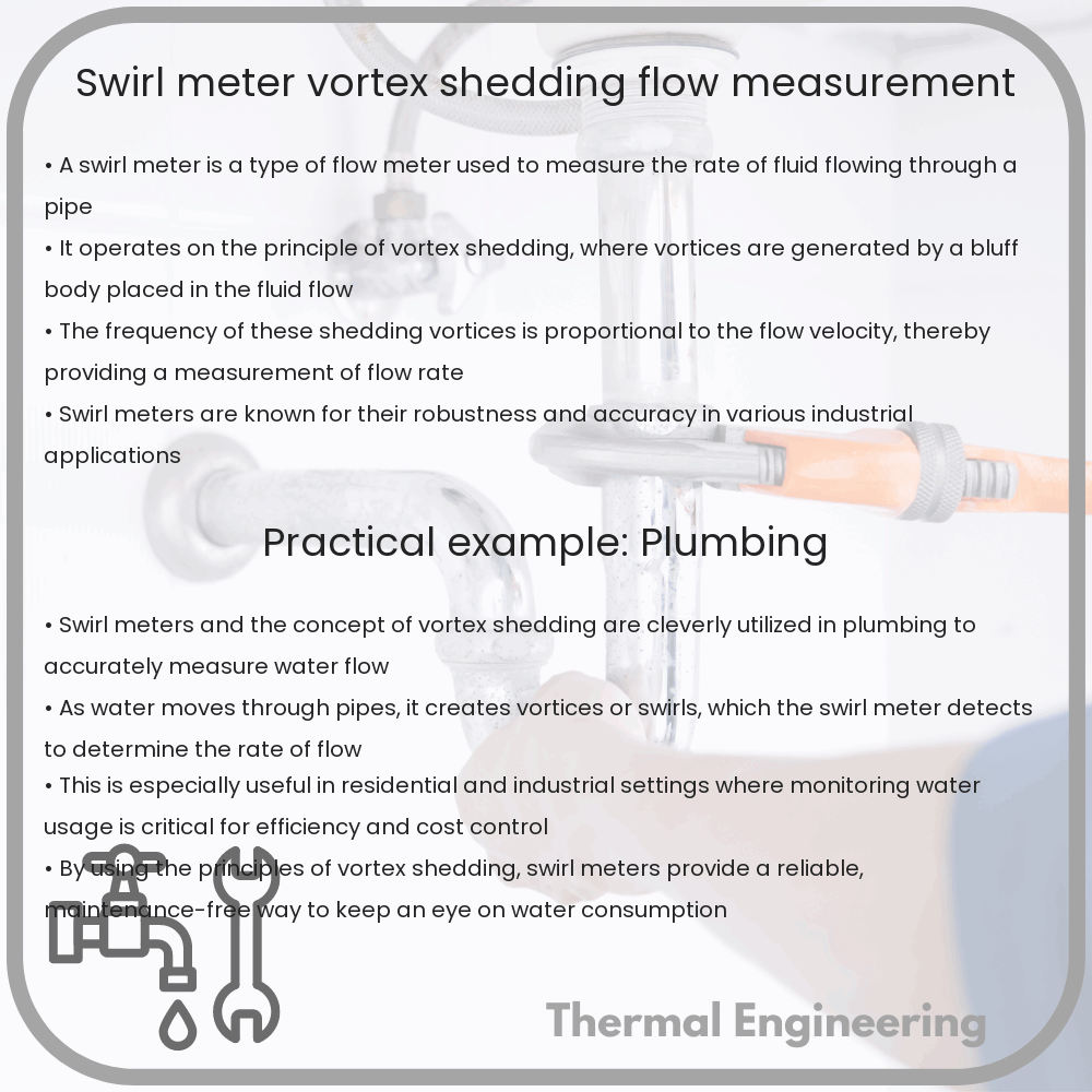
A swirl meter is a type of flow meter that utilizes the vortex shedding principle to measure the flow rate of a fluid. It consists of a simple bluff body placed in the path of the fluid flow, which causes the fluid to generate vortices. The meter detects these vortices electronically or mechanically.

The primary components of a swirl meter include:

  • A bluff body (vortex shedder)
  • Sensors for detecting vortices
  • A transmitter to process the sensor signals

As vortices are shed from the bluff body, the sensors detect and count them. Since the frequency of vortex shedding is directly proportional to the fluid velocity, it can be used to calculate the flow rate using the Strouhal number and the known dimensions of the meter.

Applications of Swirl Meters in Industry

Swirl meters are widely used in industries where precise flow measurements are necessary. Their robustness and reliability make them suitable for various applications:

  • Chemical Processing: For the regulation of reactants in a process where precise mixing ratios are critical.
  • Water and Wastewater Management: For monitoring water flow in treatment plants to ensure efficient processing and distribution.
  • Oil and Gas: For the accurate measurement of hydrocarbon flow rates, essential for both operational efficiency and safety.
  • Power Generation: For steam flow measurement in boilers and turbines to optimize the efficiency of thermal power plants.

Due to their minimal moving parts, swirl meters are not only accurate but also require minimal maintenance, making them a preferred choice in harsh industrial environments.

Conclusion

Understanding the principles of vortex shedding and the operation of swirl meters can significantly enhance the precision and reliability of flow measurement in many industrial applications. By leveraging the relationship between vortex frequency and flow velocity, these meters provide an efficient and straightforward solution for flow measurement challenges across various sectors.

Whether it’s ensuring the accurate blending of chemicals or managing vast volumes of water, swirl meters play a crucial role in maintaining operational accuracy and efficiency in industries around the globe.

Refrigeration Compressor | Types, Cooling Systems

Explore the crucial role of refrigeration compressors in cooling systems, covering types like piston, screw, scroll, rotary, and centrifugal compressors.

Refrigeration Compressor | Types, Cooling Systems

Understanding Refrigeration Compressors

At the heart of any refrigeration or air conditioning system is the compressor, a critical component that is often described as the “engine” of the cooling system. It plays a pivotal role in the refrigeration cycle, helping to maintain low temperatures by compressing the refrigerant and circulating it through the system. In this article, we will explore the different types of refrigeration compressors and discuss their applications in various cooling systems.

Types of Refrigeration Compressors

Refrigeration compressors come in various types, each with unique features and specific applications. The most common types include:

  • Piston Compressors: Also known as reciprocating compressors, these use pistons driven by a crankshaft to compress the refrigerant. They are widely used in residential and commercial settings due to their efficiency and capability to produce high pressure.
  • Screw Compressors: These compressors consist of two interlocking screws that compress the refrigerant as it moves through the threads. Screw compressors are appreciated for their durability and are commonly used in industrial refrigeration.
  • Scroll Compressors: Featuring two spiral-shaped scrolls, one fixed and one orbiting, scroll compressors compress the refrigerant by trapping it between the scrolls. They are known for their quiet operation and reliability, making them popular in commercial HVAC systems.
  • Rotary Compressors: Rotary compressors contain a rotor with slots that house vanes. These vanes slide in and out of the slots as the rotor turns, trapping and compressing the refrigerant. These are typically used in smaller systems, like residential air conditioners.
  • Centrifugal Compressors: Often used in large commercial and industrial applications, centrifugal compressors accelerate the refrigerant through a high-speed impeller and then decelerate it, which results in compression. They are valued for their ability to handle very large volumes of refrigerant with relatively low power consumption.

Cooling Systems and Their Applicability

Refrigeration compressors are integral to various cooling systems, each suitable for specific applications:

  1. Domestic Refrigerators and Freezers: These typically use piston or rotary compressors due to their high efficiency and suitability for small-to-medium scale cooling requirements.
  2. Commercial Refrigeration: This includes systems used in supermarkets or for food storage and processing, where scroll or screw compressors are favored for their reliability and ability to operate continuously.
  3. Air Conditioning Systems: Both residential and commercial air conditioning systems can use piston, scroll, or rotary compressors, depending on the size and cooling needs of the space.
  4. Industrial Chillers: Screw and centrifugal compressors are commonly used in these applications due to their capacity to handle large volumes and higher power efficiency for cooling industrial equipment or large buildings.
  5. Transport Refrigeration: Mobile refrigeration systems such as those used in trucks and trailers typically utilize piston or screw compressors due to their robustness and efficiency in variable operational conditions.

Conclusion

Refrigeration compressors are fundamental to the effectiveness and efficiency of cooling systems across various applications. Understanding the different types of compressors and their suitable applications helps in selecting the right compressor for specific cooling needs. Whether it’s maintaining fresh produce at the correct temperature or ensuring comfortable indoor environments, the choice of compressor plays a crucial role in the overall performance of refrigeration and air conditioning systems.

Scroll Compressor | Spiral, HVAC, Quiet Operation

Learn about scroll compressors, their operation, advantages, and applications in HVAC systems for enhanced efficiency and quiet performance.

Scroll Compressor | Spiral, HVAC, Quiet Operation

Understanding Scroll Compressors: Operation, Benefits, and Uses in HVAC

A scroll compressor, also known as a spiral compressor, is a device used for compressing air or refrigerant in many heating, ventilation, and air conditioning (HVAC) systems. Its unique design allows for smoother and quieter operation compared to other types of compressors.

Principles of Operation

The main components of a scroll compressor are two interleaved scrolls. One scroll is stationary (fixed scroll), while the other moves in a small orbiting motion (orbiting scroll). These scrolls are spiral-shaped, and their movement traps and compresses pockets of fluid or gas between them. As the orbiting scroll moves, the pockets of refrigerant or air progressively decrease in volume, increasing the pressure.

Components and Design

The components of a scroll compressor include:

  • Fixed Scroll: The stationary scroll that remains in place during operation.
  • Orbiting Scroll: The scroll that moves in a circular, orbiting motion to compress the refrigerant or air.
  • Motor: Drives the orbiting scroll.
  • Discharge Port: The point where compressed gas exits the compressor.

The design of scroll compressors offers a continuous compression process, as new pockets of air are trapped and compressed with every turn of the orbiting scroll. This leads to a continuous flow of compressed air at the outlet, minimizing pulsations and vibrations typical in other compressor designs.

Advantages of Scroll Compressors

Scroll compressors are highly valued in HVAC applications for several reasons:

  • Quiet Operation: With fewer moving parts and a more constant airflow, scroll compressors operate with significantly less noise compared to reciprocating or rotary compressors.
  • Efficiency: These compressors are more energy-efficient, primarily due to their ability to compress continuously without having significant energy losses to valve or port inefficiencies.
  • Reliability: The simplicity of the scroll design, having fewer moving parts, reduces the chances of mechanical failures, thus enhancing the durability and reliability of the unit.
  • Compact Design: Scroll compressors tend to be more compact, making them easier to incorporate into various HVAC systems without requiring a lot of space.

Applications in HVAC

Scroll compressors are widely used in HVAC systems due to their efficiency and quiet operation. They are particularly suitable for residential and commercial air conditioning systems, refrigerators, and heat pumps. Their ability to handle varying load demands makes them highly effective in environments where the need for air conditioning or refrigeration varies throughout the day.

Conclusion

Scroll compressors offer a blend of quiet operation, efficiency, and reliability, making them a preferred choice in modern HVAC systems. Their unique design and operation principles cater to a broad range of applications where reducing noise while maintaining efficiency is crucial. As technology advances, the role of scroll compressors in HVAC systems is expected to grow, further enhancing comfort and energy efficiency in homes and commercial buildings alike.