Facebook Instagram Youtube Twitter

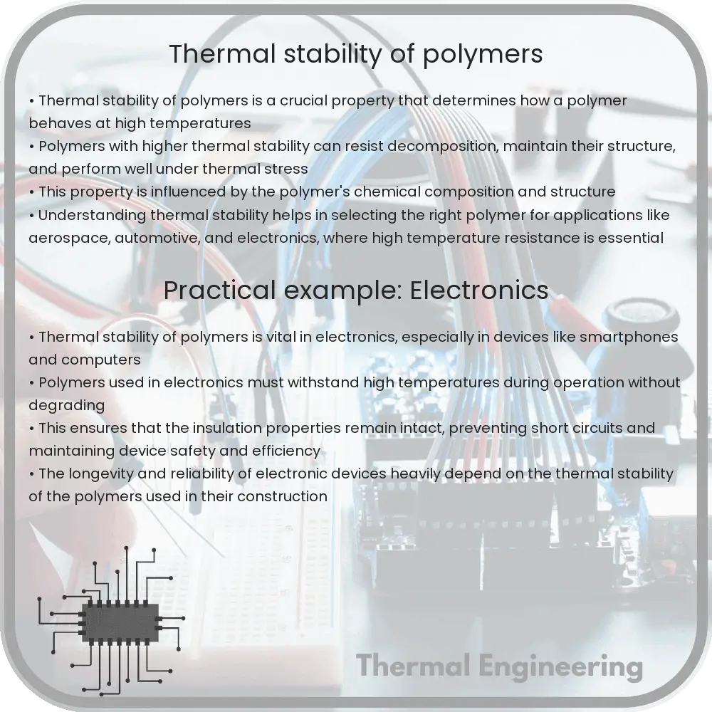
Thermal stability of polymers

Explore the factors, analytical methods, and engineering implications of polymer thermal stability.
Thermal stability of polymers

Understanding the Thermal Stability of Polymers

Thermal stability is a critical aspect of polymer science, influencing how materials perform under high temperatures and during manufacturing processes such as extrusion and molding. This stability determines the range of practical applications for polymers, from automotive parts to household appliances. In this article, we delve into the factors influencing thermal stability, methods of analysis, and the implications for material engineering.

Factors Affecting Thermal Stability

The thermal stability of polymers is influenced by several factors, which include the chemical structure of the polymer, the presence of stabilizing additives, and environmental conditions like oxygen availability and humidity. Here’s a closer look:

  • Chemical Structure: Polymers with aromatic rings or high degrees of cross-linking generally exhibit greater thermal stability due to the strong carbon-carbon bonds. For instance, polyimides and polybenzimidazoles are known for their exceptional heat resistance.
  • Additives: Stabilizers such as antioxidants and flame retardants can significantly enhance a polymer’s ability to withstand heat. These additives work by either capturing free radicals produced during thermal degradation or by promoting the formation of a protective char layer on the polymer’s surface.
  • Processing History: Thermal history, including processing temperatures and times, can affect a polymer’s structure and its subsequent thermal stability. Prolonged exposure to high temperatures can lead to changes in molecular weight and degree of crystallinity, which in turn affect stability.

Measuring Thermal Stability

The thermal stability of polymers is typically assessed using a variety of analytical techniques that measure changes in physical and chemical properties as a function of temperature. Common methods include:

  1. Thermogravimetric Analysis (TGA): TGA measures the amount of weight loss a polymer experiences as it is heated. This method provides information about the thermal stability and decomposition temperatures of polymers.
  2. Differential Scanning Calorimetry (DSC): DSC monitors heat flow associated with transitions in the polymer such as melting, crystallization, and decomposition. This is crucial for determining the operational temperature limits of a polymer.
  3. Dynamic Mechanical Analysis (DMA): DMA measures changes in a polymer’s mechanical properties with temperature. The glass transition temperature determined by DMA is also a useful indicator of a material’s thermal stability.

Implications in Engineering

The thermal stability of polymers plays a pivotal role in determining the suitability of materials for specific applications. For instance, polymers used in high-temperature environments such as under-the-hood automotive components or aircraft interiors need to maintain structural integrity and functionality despite the heat. Engineers must carefully select or design polymers that meet these demanding specifications without compromising on cost or processability.

In addition, understanding thermal degradation mechanisms can aid in improving the recyclability of polymers. By selecting thermally stable materials that degrade in a predictable manner, engineers can enhance the lifecycle of products and minimize environmental impact.

Conclusion

The thermal stability of polymers is a foundational property that influences their processing, performance, and longevity. Through the careful study of polymer chemistry, the judicious use of additives, and the selection of appropriate analysis techniques, engineers can develop materials that stand up to the demands of today’s high-performance applications. As polymer technology advances, the push for materials that can handle increasingly extreme conditions continues to grow, highlighting the importance of thermal stability in material engineering.
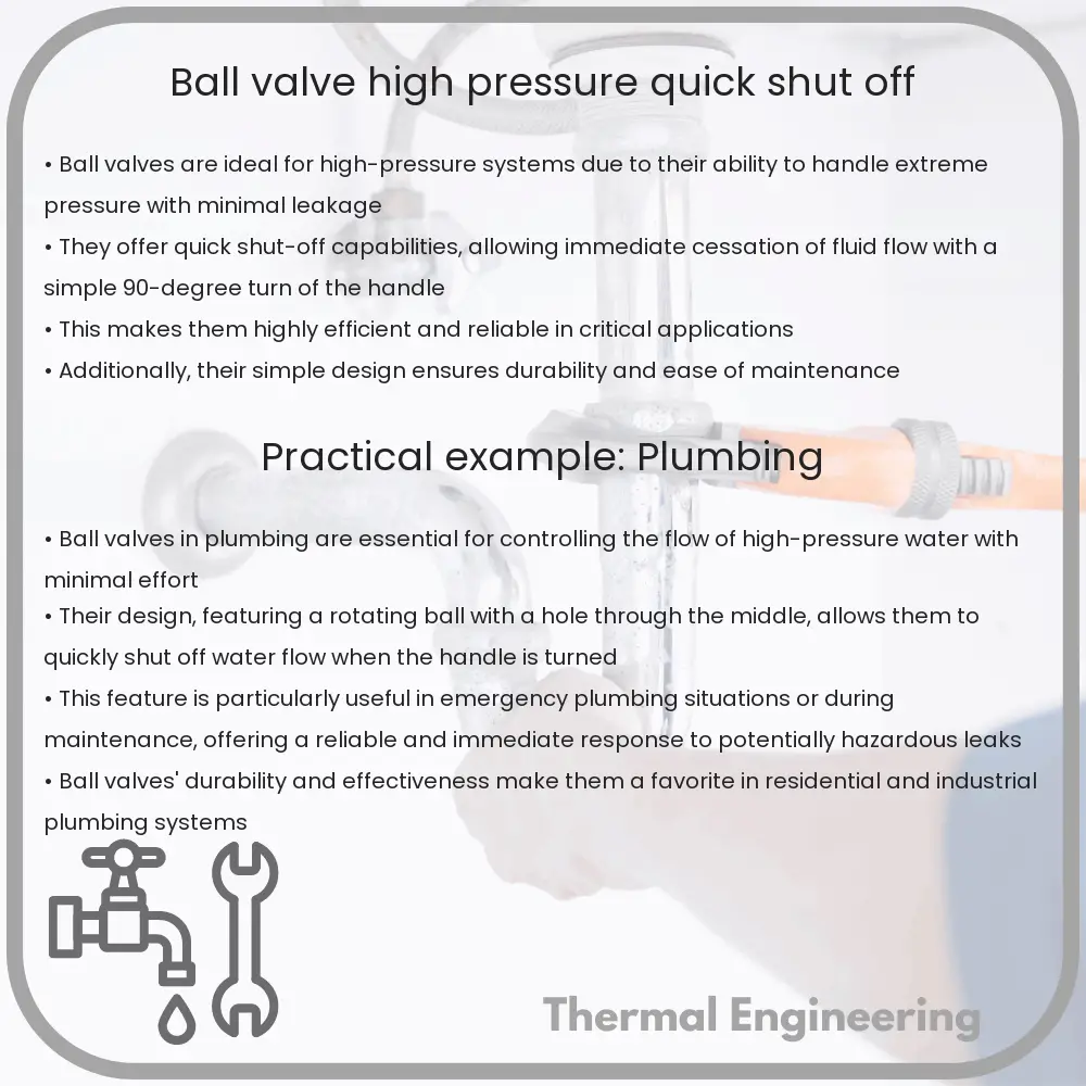
Ball Valve | High Pressure, Quick Shut-off

Learn about ball valves, their structure, advantages in high-pressure applications, and common materials and uses.

Ball Valve | High Pressure, Quick Shut-off

Understanding Ball Valves: High-Pressure, Quick Shut-off Applications

Ball valves are a type of valve commonly used in a variety of industrial and residential applications due to their durability and reliability. They are especially valued in high-pressure situations and for their ability to provide secure shut-off quickly. In this article, we’ll explore what makes ball valves suited for these roles, the structure of these valves, and why they are preferred in certain applications.

Structure and Working Principle of Ball Valves

At its core, a ball valve features a spherical disc, the part of the valve which controls the flow through it. The sphere has a hole, or port, through its center. When the port is aligned in the same direction as the pipeline, it is open, and fluid can flow through; when it is perpendicular to the pipeline, it is closed, blocking the flow.

The ball is controlled by a handle that makes it easy to adjust the flow. This simplicity in design allows for not only quick operation but also a reliable means of controlling the flow, making the valve very secure when in the closed position. This quick action is crucial in applications where rapid shut-off is needed to prevent accidents or damage to a system due to sudden changes in pressure or flow.

Advantages of Using Ball Valves in High-Pressure Applications

  • Durability: Ball valves are capable of withstanding high-pressure and temperature, making them suitable for high-pressure applications where other valves might fail.
  • Minimal Leakage: The tight seal made by the fitting of the spherical disc against the valve body ensures minimal leakage, which is crucial in high-pressure applications.
  • Long Service Life: Due to their simple structure, ball valves have fewer parts that can wear out or fail compared to other valve types. This simplicity extends their service life even under high-stress conditions.

Materials Commonly Used in High-Pressure Ball Valves

Ball valves can be made from a variety of materials, each selected for specific properties like strength, chemical resistance, and thermal properties. Common materials include:

  • Stainless Steel: Known for its resistance to corrosion and oxidation, stainless steel is a common choice for high-pressure environments.
  • Brass: While generally used in lower pressure applications, certain alloys and treatments can make brass suitable for higher pressures.
  • Plastic: Some high-strength plastics can be used in lower temperature and moderately high-pressure environments. Their advantage is in their resistance to corrosion.

Applications of High-Pressure Ball Valves

Due to their versatility and durability, ball valves are used in a variety of applications. Some common sectors utilizing high-pressure ball valves include:

  • Oil and Gas Industry: Used for controlling the flow of both gaseous and liquid fuels under high-pressure conditions.
  • Chemical Manufacturing: Crucial for processes that require the handling of high-pressure chemicals and fluids.
  • Water and Wastewater Treatment: Used in high-pressure lines to manage the flow of water and treatment chemicals.
  • Residential Plumbing: Suitable for managing the water supply, especially in high-pressure municipal systems or pumping applications.

Conclusion

Ball valves provide an efficient and secure method of controlling fluid flow in high-pressure environments, acting quickly to shut off flow when needed. The combination of simple design, durability, and reliability under pressure makes them an indispensable tool in many engineering applications. Whether in industrial settings or residential systems, their role in safe and effective fluid management is critical.

Understanding the design, materials, and advantages of high-pressure ball valves assists in selecting the right valve for specific applications, ensuring safety, effectiveness, and longevity of the system.

Peristaltic Pump | Sanitary Transfer, Lab Use

Learn about peristaltic pumps, their unique operation, applications across various industries, and the advantages they offer for sanitary fluid transfer.

Peristaltic Pump | Sanitary Transfer, Lab Use

Understanding Peristaltic Pumps

Peristaltic pumps play an essential role in various applications, ranging from biomedical research to food production. These pumps, characterized by their unique design and operation principle, offer significant advantages for sanitary transfer and laboratory contexts.

How Peristaltic Pumps Work

A peristaltic pump operates through a process called peristalsis, mirroring the method by which food is moved through the esophagus. The pump consists of a flexible tube fitted inside a circular pump casing. Around this tube, rollers or shoes compress the tubing as they rotate, pushing the fluid forward. This design ensures that the fluid only contacts the tubing, thus preventing contamination.

The complete enclosure of the fluid also minimizes the risk of contamination, an essential feature for hygienic and sterile applications. As the rollers pass over the tube, they pinch it closed, which forces whatever fluid is inside to move along the tube. Once the pressure from the roller is released, the tube returns to its original shape, creating a vacuum and drawing more fluid into the tube. This cycle repeats continuously as the roller moves.

Applications of Peristaltic Pumps

Given their sanitary operation, peristaltic pumps are widely used in industries that require sterile processes. Here are some of the primary applications:

  • Medical and Laboratory Use: In medical labs, peristaltic pumps facilitate the safe and precise transfer of fluids. They are commonly used in dialysis machines, IV fluid transfers, and automated blood analyzers.
  • Food and Beverage Industry: The food and beverage industry benefits from peristaltic pumps because they prevent product contamination and can handle viscous fluids, including dairy products and sauces.
  • Chemical Application: Peristaltic pumps are suitable for pumping aggressive chemicals as the pump’s mechanical components do not come into contact with the chemicals.
  • Waste Water Treatment: These pumps are effective in handling slurries, viscous, shear-sensitive or aggressive fluids, making them ideal for use in water treatment facilities.

Advantages of Peristaltic Pumps

Peristaltic pumps offer several advantages that make them appealing across various fields:

  1. Minimized Contamination Risk: Since the fluid remains within the tubing, there is minimal risk of the fluid being contaminated by the pump or the environment.
  2. Low Maintenance: With fewer moving parts in contact with the fluid, these pumps require less maintenance compared to other pump types.
  3. Gentle Pumping Action: The gentle squeezing action is ideal for handling shear-sensitive fluids like live cell cultures or proteins without denaturing them.
  4. Versatility: Peristaltic pumps can handle a wide range of fluids, including abrasive and viscous substances, adding to their versatility.
  5. Self-priming and Dry Running Capability: These pumps can effectively self-prime and run dry for extended periods without suffering damage.

Conclusion

Peristaltic pumps are indispensable in scenarios requiring high levels of hygiene, precision, and efficiency. Their distinctive operating mechanism and robust design make them suitable for a broad spectrum of applications ranging from medical laboratories to wastewater treatment facilities. Understanding how these pumps work and where they can be utilized can help industries better choose and implement fluid transfer systems that meet their needs efficiently and hygienically.

Steam Trap | Condensate Removal, Energy Efficiency

Learn about steam traps, essential for condensate removal and boosting energy efficiency in industrial steam systems.

Steam Trap | Condensate Removal, Energy Efficiency

Understanding Steam Traps: Essential Components for Condensate Removal and Energy Efficiency

Steam traps are a critical component in steam systems used in various industries, including refining, chemical processing, and power generation. They play a crucial role in enhancing system efficiency, reducing energy consumption, and minimizing operational costs. In this article, we will explore the function of steam traps, the importance of condensate removal, the impact on energy efficiency, and the different types of steam traps used in engineering applications.

What is a Steam Trap?

A steam trap is a device that automatically regulates the discharge of condensate, non-condensable gases, and air without letting steam escape. Steam is often used for heating applications in industrial processes because it is an efficient carrier of energy. However, as steam loses its heat, it condenses into water, which must be removed efficiently and quickly through the use of steam traps.

Importance of Efficient Condensate Removal

Efficient condensate removal is crucial for several reasons:

  • Safety: Accumulated condensate can cause water hammer, a sudden condensation of steam that creates a shock wave within the pipeline, potentially damaging the system and posing safety risks.
  • Energy Efficiency: Removing condensate allows steam to flow more freely, reducing energy losses and improving the efficiency of the heating system.
  • Equipment Longevity: Efficiently removing condensate minimizes the risk of corrosion and wear in pipes and equipment, thereby extending their lifespan and reducing maintenance costs.

How Steam Traps Boost Energy Efficiency

Steam traps contribute to energy efficiency by preventing steam leakage. Properly functioning steam traps ensure that only condensate and non-condensable gases are expelled, keeping the valuable steam within the system. This retention of steam means less fuel is required to generate steam, leading to significant energy savings and reduced environmental impact.

Types of Steam Traps

There are several types of steam traps used across industries, each with unique mechanisms and suitable for different operational conditions:

  1. Mechanical Traps: These traps operate on the principle of buoyancy and include ball float and inverted bucket types. They are effective at discharging air and condensate while remaining closed to steam.
  2. Thermostatic Traps: Thermostatic traps, including bimetallic and bellows types, function based on the expansion and contraction of materials in response to temperature changes. They are ideal for removing air and condensate at near-steam temperatures.
  3. Thermodynamic Traps: These traps use the dynamics of steam and condensate to operate a disc or piston, which is typically beneficial for high-pressure systems and can handle blast discharge of condensate.

Conclusion

Steam traps are an indispensable part of steam systems in many industrial applications. Their ability to efficiently remove condensate, prevent steam leakage, and thereby enhance energy efficiency, makes them pivotal for cost-effective and safe operations. Selecting the right type of steam trap and maintaining it properly can lead to substantial improvements in system performance and energy savings.

Understanding different types of steam traps and their applications helps facility managers and engineers make informed decisions, optimizing the performance and longevity of heating systems.

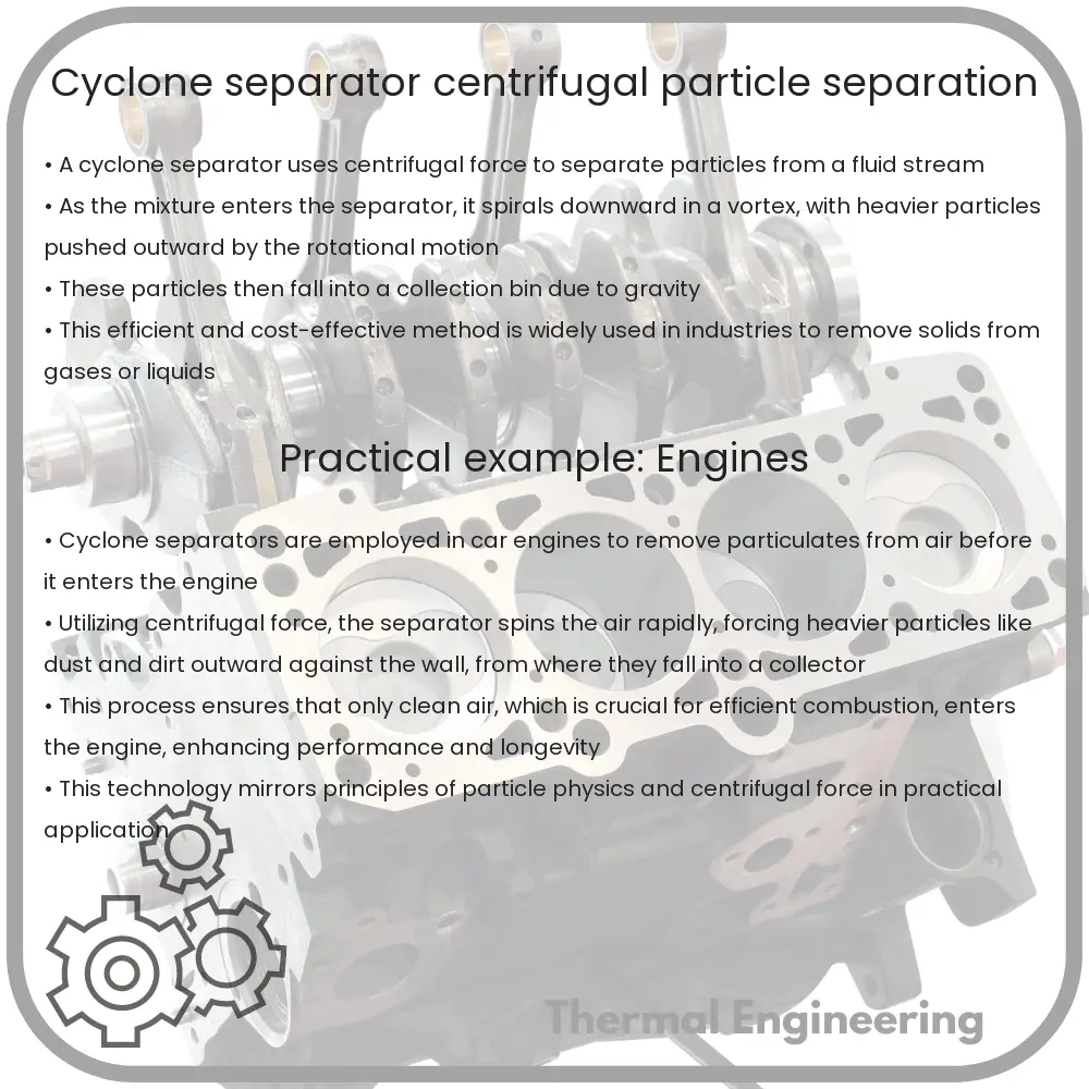
Cyclone Separator | Centrifugal, Particle Separation

Learn how cyclone separators use centrifugal force to efficiently separate particles from fluid streams in various industries.

Cyclone Separator | Centrifugal, Particle Separation

Understanding Cyclone Separators: Principles and Applications

A cyclone separator is a key piece of equipment used in the field of engineering to separate particulate matter from fluid streams. This separation is achieved through the use of centrifugal, gravitational, and inertial forces, making it an efficient and cost-effective solution in various industries. Let’s dive deeper into how cyclone separators work and where they are typically used.

How Cyclone Separators Work

The basic principle behind a cyclone separator is the use of centrifugal force to separate particles from a fluid stream. When the mixture enters the cyclone separator, it is subjected to a spin using a spirally guided configuration. Due to the centrifugal force, heavier particles are flung to the outer walls of the cyclone, while the cleaned fluid moves upwards and exits through the top.

The efficiency of a cyclone separator depends on several factors, including the particle size and density, the fluid velocity, and the dimensions of the cyclone itself. The mathematics behind the force exerted on the particles can be found using the equation:

Fcentrifugal = m * (v2 / r)

  • m represents the mass of the particle,
  • v represents the tangential velocity,
  • r is the radius of the cyclone.

This force leads to the efficient separation of solids from liquids or sorting of particles by size, making cyclones critical in processes where purity and particle segregation are paramount.

Applications of Cyclone Separators

Cyclone separators are widely used across various industries owing to their simple design and effectiveness in separating particles from fluid streams. Common applications include:

  • Natural Gas Processing: To remove sand and other solid contaminants from the gas before it enters processing equipment.
  • Petroleum Refining: Used in fluid catalytic cracking units to separate catalyst particles from hydrocarbon vapors.
  • Air Pollution Control: To collect particulate matter as part of systems aimed at reducing air emissions.
  • Manufacturing Processes: In cement production, metal smelting, and other manufacturing processes where control of airborne particulate is essential.

Advantages and Limitations

Cyclone separators offer several advantages which make them an attractive option for particle separation:

  • Low Initial Cost: Compared to other types of filters, cyclones have a lower initial purchase and installation cost.
  • Low Maintenance: They have no moving parts, which translates to minimal maintenance needs and lower operational costs over time.
  • High Temperature and Pressure Capability: They can operate under high-temperature and high-pressure conditions, which is ideal for processing industries.
  • Versatility: Can be used with almost any gas and particulate load combination.

However, there are also limitations to consider:

  • Size of Particles: Efficiency decreases with smaller particles—typically less effective with particles smaller than 10 micrometers.
  • Humidity: The presence of moisture can affect performance, leading to potential clogging issues.
  • Limited to Dry Particles: Generally, cyclones are not suitable for wet mixtures unless specifically designed for such conditions.

Conclusion

Cyclone separators, through the simple yet effective mechanism of centrifugal separation, continue to play a crucial role in industry. With their ability to handle high temperatures and pressures, along with minimal maintenance requirements, they are a valuable tool for engineers working to optimize the efficacy and cost-efficiency of their processes. As advances in materials and designs improve, the applications and capabilities of cyclone separators are likely to expand, further solidifying their place in industrial applications.

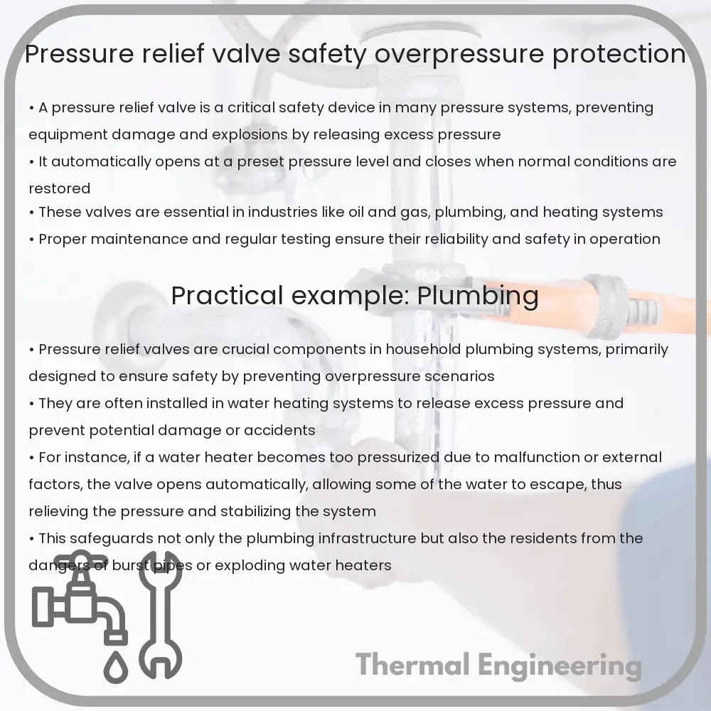
Pressure Relief Valve | Safety, Overpressure Protection

Learn about the essential role and functioning of pressure relief valves in maintaining system safety and managing overpressure.

Pressure Relief Valve | Safety, Overpressure Protection

Understanding Pressure Relief Valves: A Key to Safety and Overpressure Protection

Pressure relief valves are critical components in various mechanical systems, helping prevent accidents and ensuring the stability of operations in industries such as oil and gas, chemicals, and thermal power generation. These devices are engineered to provide a safety measure for pressurized systems, automatically releasing gases or liquids when the pressure within a system exceeds a predefined limit.

How Pressure Relief Valves Work

At its core, a pressure relief valve (PRV) is designed to protect equipment and personnel by releasing excessive pressure from a system when it reaches the pressure limit set for safe operations. The mechanism involves a spring-loaded valve which opens allowing the excess pressure to escape, thereby averting potential hazards.

  • The set pressure is the predetermined pressure at which the relief valve is configured to open. This setting ensures that the valve activates before the system pressure reaches a critical level.
  • The overpressure is typically a small percentage above the set pressure, usually about 3% to 5%, allowing some leeway for the valve to fully open without causing system interruptions during minor fluctuations.
  • The blowdown is the pressure drop after the valve opens, required to reset the valve back to its closed position. This is usually a lower percentage, such as 2% to 4% below the set pressure, ensuring the system’s pressure is sufficiently reduced.

Types of Pressure Relief Valves

There are several types of pressure relief valves, each suited for specific applications and operational conditions:

  1. Safety Valves: Often used in gas or vapor systems, these valves are spring-operated and rapidly open when the set pressure is exceeded.
  2. Pressure Safety Relief Valves (PSRVs): These can handle both liquid and gas mediums. They start to open at the set pressure and continue to discharge gradually.
  3. Pilot Operated Relief Valves: Controlled by a pilot valve instead of a spring, these valves are typically more accurate and stable under varying conditions.

Key Features and Materials

Pressure relief valves are constructed using materials capable of withstanding harsh environments and high pressures. Common materials include stainless steel, carbon steel, and brass. They also feature various seals and diaphragms made from elastomers like Viton® and Teflon® to ensure durability and leak-proof operation.

Applications in Industry

PRVs are essential in industries where overpressure conditions are likely. They include:

  • Oil and Gas: Used on drilling rigs, production platforms, and refineries to control the pressures of hydrocarbon processing systems.
  • Chemical Manufacturing: PRVs guard against the dangerous build-up of pressure in chemical reactors and other enclosed vessels.
  • Power Generation: Critical in preventing overpressure in boilers and steam systems.

Maintenance and Testing

Regular maintenance and testing are vital to ensure that pressure relief valves function correctly. This includes routine inspections, testing for correct opening pressure, and checking for signs of wear or corrosion. Utilizing certified technicians to perform these tasks can prevent operational failures and extend the lifespan of the equipment.

Safety and Compliance

Pressure relief valves must adhere to international safety standards and codes, such as those from the American Society of Mechanical Engineers (ASME). Compliance with these standards ensures the reliability and safety of the valves used in industrial applications.

Ultimately, pressure relief valves are indispensable in maintaining the safety and efficiency of high-pressure systems. Understanding their function and ensuring they are properly maintained can help mitigate risks associated with overpressure conditions, safeguarding both personnel and equipment.

Rotary Screw Compressor | Continuous Air, Efficiency

Learn how rotary screw compressors work, their components, benefits, and applications in various industries, ensuring efficient and continuous air supply.

Rotary Screw Compressor | Continuous Air, Efficiency

Understanding Rotary Screw Compressors

Rotary screw compressors are widely used in various industrial, manufacturing, and air conditioning systems due to their efficiency and ability to provide continuous air supply. This type of compressor utilizes two interlocking screws, often referred to as rotors, which compress the air as it moves through the compressor.

How Does a Rotary Screw Compressor Work?

The basic operation of a rotary screw compressor begins when air enters through an intake valve and fills the space between the helical screws. As the screws rotate, the volume of the spaces between them decreases, which compresses the air. This process typically occurs in a continuous flow, making rotary screw compressors ideal for tasks needing a steady, reliable air supply.

Key Components of Rotary Screw Compressors

  • Screws (Rotors): Usually one male and one female rotor mesh together to trap and compress air.
  • Drive Motor: Provides the necessary power to the rotors enabling them to rotate and compress air.
  • Air End: A crucial part where the actual compression of air occurs.
  • Inlet and outlet valves: Regulate the flow of air into and out of the compressor.
  • Oil Filter: In oil-injected rotary screw compressors, oil is used not only for lubrication but also for sealing and cooling. The oil filter removes any impurities from the circulating oil.

Benefits of Using Rotary Screw Compressors

Rotary screw compressors offer several advantages over other types of compressors like reciprocating or centrifugal compressors:

  1. Continuous Air Supply: They can run 24/7 without needing a break, making them suitable for operations requiring a constant air supply.
  2. Energy Efficiency: These compressors can vary their speed to match the air demand, significantly reducing energy consumption.
  3. Lower Noise Levels: Generally quieter than reciprocating compressors, making them ideal for indoor environments.
  4. Durability: With fewer moving parts and a less pulsating operation, rotary screw compressors tend to have a longer operational life.

Applications of Rotary Screw Compressors

Due to their efficiency and durability, rotary screw compressors have a wide range of applications:

  • Manufacturing: Used in factories for operating pneumatic tools, handling material, and product finishing.
  • Automotive: Utilized in air tools and paint systems within automotive manufacturing.
  • Construction: Helpful in powering air tools and machinery on construction sites.
  • Pharmaceuticals: They ensure clean, controlled air supply, vital in pharmaceutical production.

Conclusion

Rotary screw compressors are integral to various fields, providing efficient, reliable, and continuous air supply with relatively low maintenance needs. Their versatility and adaptability to different industrial environments make them a preferred choice for a wide array of applications, underpinning their importance in modern industrial operations.

Waste-to-energy thermal processes

Learn about waste-to-energy thermal processes, including incineration, pyrolysis, and gasification, their efficiencies, and environmental impacts.

Waste-to-energy thermal processes

Understanding Waste-to-Energy Thermal Processes

With the increasing global focus on sustainability and waste management, waste-to-energy (WTE) technologies have become a crucial component in modern waste disposal methods. WTE technologies use waste materials as a fuel, converting them into useful forms of energy, such as electricity and heat, through a variety of thermal processes. This article explores some of the main thermal processes used in waste-to-energy conversion, highlighting their principles, benefits, and challenges.

1. Incineration

Incineration is the most common and widely used thermal treatment for waste-to-energy conversion. It involves the combustion of organic substances contained in waste materials under high temperature, typically above 850°C. The process reduces the volume of waste by about 95-96% and converts it into ash, flue gases, and heat, which can then be used to generate steam and electricity.

  • Efficiency: Modern incineration plants are equipped with energy recovery systems that enable them to achieve energy efficiencies of 14-28%.
  • Emissions Control: To manage emissions, advanced air pollution control systems are used to capture and treat flue gases, significantly reducing the release of pollutants.
  • Applications: Widely used in countries with limited land area for landfills such as Japan, Sweden, and the Netherlands.

2. Pyrolysis

Pyrolysis is a process of chemically decomposing organic materials at elevated temperatures in the absence of oxygen. Temperatures typically range between 400°C and 700°C. This process converts waste into three products: a solid residue known as char, liquid oils (often referred to as bio-oils), and syngas.

  • Variants: Depending on the reactor design and operational conditions, pyrolysis can be slow or fast, impacting the yield and characteristics of the by-products.
  • Flexibility: The syngas and oils produced can be used for various applications including the production of chemicals and as fuel for engines and turbines.

3. Gasification

Gasification is similar to pyrolysis in that it involves the thermal decomposition of carbonaceous materials, but it occurs at higher temperatures (between 700°C and 1200°C) and with a controlled amount of oxygen and/or steam. This process primarily converts organic materials into a combustible gas mixture consisting mainly of carbon monoxide, hydrogen, and trace amounts of carbon dioxide.

  • Energy Production: The syngas produced from gasification can be used to generate electricity and as a feedstock for producing various chemicals.
  • Environmental Impact: Gasification typically produces fewer pollutants than incineration due to the lower levels of oxygen involved in the process.

Challenges and Future Outlook

While waste-to-energy technologies offer significant benefits by diverting waste from landfills and producing energy, they also face several challenges. These include high initial capital costs, the need for sophisticated emission control technologies, and public opposition due to concerns about emissions and incineration by-products. Furthermore, the variability of waste composition can impact the efficiency and stability of thermal processes.

Research is ongoing to enhance the efficiency, reduce the costs, and minimize the environmental impact of these technologies. Innovations in catalyst development, reactor design, and process integration hold promise for the future of waste-to-energy technologies. As we move towards a more sustainable world, the role of WTE processes in managing waste and providing renewable energy can be expected to grow significantly.

The exploration and improvement of waste-to-energy thermal processes are essential to balancing the demands of energy production, waste reduction, and environmental preservation, making this field a key component of sustainable urban development strategies.

Cavitation Plate | Vapor Prevention, Pumps/Turbines

Learn how cavitation plates prevent vapor formation in pumps and turbines by stabilizing pressure and optimizing flow.

Cavitation Plate | Vapor Prevention, Pumps/Turbines

Understanding Cavitation Plates: Essential for Vapor Prevention in Pumps and Turbines

Cavitation, a common phenomenon in the operation of pumps and turbines, can cause significant wear and tear on equipment, leading to reduced efficiency and damage. In this article, we will explore what cavitation is, why it occurs, and how cavitation plates are used to manage and mitigate its effects.

What is Cavitation?

Cavitation occurs when the local pressure in a fluid drops below the vapor pressure of the fluid. This leads to the formation of vapor bubbles within the fluid, which collapse as they move into higher pressure regions. The collapse of these bubbles produces shock waves that can damage machinery surfaces, especially those of impellers and turbines.

Causes of Cavitation in Pumps and Turbines

Cavitation typically arises from:

  • High flow velocities: Increased velocities cause a decrease in the pressure in certain regions of the pump or turbine.
  • Rapid changes in direction: Sudden changes in the direction of flow lead to changes in pressure, facilitating vapor bubble formation.
  • Inconsistent fluid intake: Irregular fluid levels can lead to areas of low pressure where cavitation can initiate.

The Role of Cavitation Plates

Cavitation plates are specially designed structures mounted near the propellers or impellers of turbines and pumps. They serve several critical functions:

  1. Pressure Stabilization: By altering the flow characteristics around the blades, cavitation plates help stabilize the pressure across the machinery. This decreases the likelihood of pressures dropping below vapor pressure.
  2. Flow Optimization: These plates help in smoothing the flow before it reaches critical components, reducing turbulence and the resultant wear and cavitation risks.
  3. Protection: They act as a physical barrier, shielding the impeller or turbine blades from potential impacts and bubbles produced by cavitation.

Design and Installation of Cavitation Plates

The design of cavitation plates is crucial and must be tailored to the specific conditions and architecture of each pump or turbine system. Factors such as size, shape, and positioning significantly influence their effectiveness. Installation is typically at a location where flow separation is likely to occur, or where fluid speeds transition sharply.

Conclusion

Cavitation plates are vital components in the management of cavitation in pumps and turbines. By understanding and utilizing these plates effectively, engineers can greatly enhance the longevity and efficiency of hydraulic machinery. The prevention of cavitation not only safeguards the equipment but also ensures optimal operational conditions, resulting in significant cost savings and maintenance reductions over time.

Coriolis Flow Meter | Mass Measurement, High Accuracy

Learn about the Coriolis flow meter, its operation principle, high accuracy in mass measurement, and diverse industrial applications.

Coriolis Flow Meter | Mass Measurement, High Accuracy

Understanding the Coriolis Flow Meter: Mass Measurement and High Accuracy

The Coriolis flow meter, named after the French scientist Gaspard-Gustave de Coriolis, is a sophisticated device used in the process and chemical industries for the measurement of mass flow and density. It is renowned for its high accuracy and reliability in various applications ranging from oil and gas production to pharmaceuticals and food processing. This article will explore the fundamental principles, advantages, and common applications of the Coriolis flow meter.

Principles of Operation

The operating principle of the Coriolis flow meter is based on the Coriolis effect. When a moving fluid is passed through a vibrating tube, the vibration creates inertia-induced forces on the fluid. As the fluid flows through the oscillating flow tubes, it experiences a Coriolis acceleration. This results in a phase shift or a twist in the tube, which is proportional to the mass flow rate of the fluid. Sensors at the inlet and outlet of the tube detect this phase shift, and from these measurements, the mass flow rate is calculated.

Mathematically, the mass flow rate (m) is directly proportional to the phase shift (ΔΦ) observed in the tube. The relationship can be expressed as:

m = K * ΔΦ

where K is a calibration constant determined by the characteristics of the meter.

Key Advantages

  • Direct Mass Measurement: Unlike other flow meters that measure volumetric flow and require corrections for fluid properties, Coriolis meters measure mass flow directly. This eliminates the need for temperature and pressure compensations, enhancing accuracy.
  • High Accuracy: Coriolis flow meters are highly accurate, typically within ±0.1% to ±0.5% of the flow rate. Their ability to maintain accuracy over a wide range of flow rates and conditions is a significant advantage.
  • Measurement of Various Parameters: Besides mass flow, Coriolis meters can simultaneously measure fluid density and temperature, providing comprehensive insights into the flowing medium.
  • No Moving Parts: The absence of moving parts reduces maintenance needs and enhances the meter’s durability and reliability.

Applications

Coriolis flow meters are used across a diverse range of industries due to their versatile benefits:

  1. Oil and Gas: They are crucial for the accurate measurement of hydrocarbons in upstream, midstream, and downstream processes.
  2. Pharmaceuticals: Ensuring precise formulation and compliance with stringent quality controls.
  3. Food and Beverage: Used for the measurement of ingredients in batching processes where precision is critical.
  4. Chemicals: Essential in chemical dosing applications where the chemical reaction depends on precise proportioning.

Conclusion

The Coriolis flow meter is a powerful tool in the arsenal of modern industrial technology. Its ability to deliver precise and direct measurement of mass flow and density makes it indispensable in industries where accuracy and efficiency are paramount. By understanding how it works and its applications, industries can better select and implement these devices to enhance their operations and product quality.

As technology advances, the development and refinement of Coriolis flow meters continue, promising even greater functionality and adaptability to meet the evolving needs of modern industries.