Facebook Instagram Youtube Twitter

Hydraulic Ram | Water Lifting, Types, Remote Supply

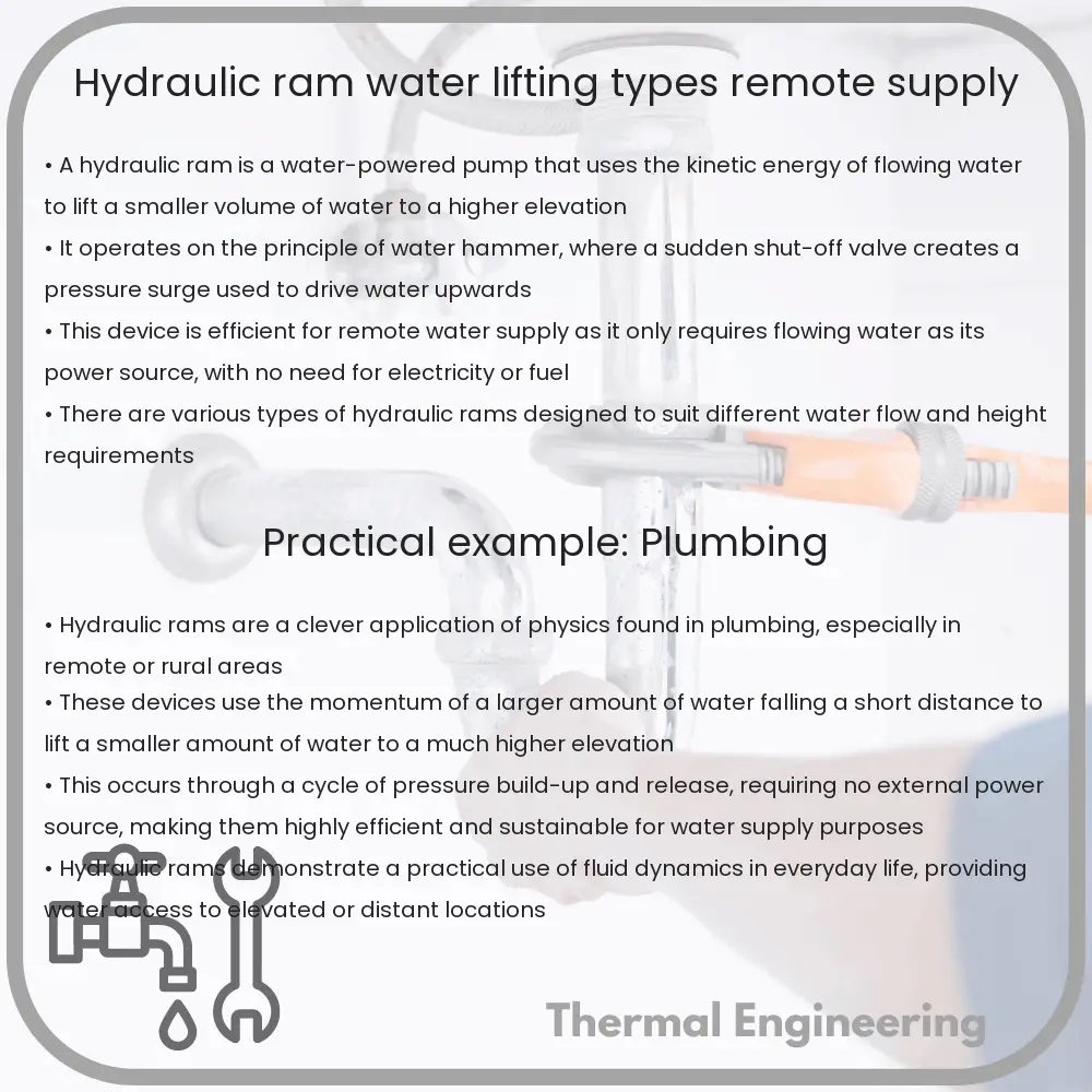
Understanding the hydraulic ram: an innovative device utilizing water’s kinetic energy for elevated water pumping without external power.
Hydraulic Ram | Water Lifting, Types, Remote Supply

Understanding the Hydraulic Ram: Water Lifting, Types, and Remote Supply

The hydraulic ram, or hydram, is a fascinating piece of engineering technology that has been used since the late 18th century for the purpose of lifting water without the need for an external power source. This simple yet effective device uses the power of water’s kinetic energy to pump a portion of that water to a height greater than its original source. In this article, we’ll explore how hydraulic rams work, their types, and their applications, particularly in remote water supply systems.

How Does a Hydraulic Ram Work?

The operation of a hydraulic ram is based on a principle known as water hammer, a phenomenon that occurs when a flowing fluid is suddenly forced to stop or change direction. The basic components of a hydraulic ram include:

  • Inlet pipe: Water flows through this pipe with kinetic energy due to its elevation or slope.
  • Drive pipe: This is a narrower pipe that increases the velocity of the water.
  • Waste valve: Also known as the impulse valve, it opens and closes under the force of the water, creating the water hammer effect.
  • Pressure vessel: Contains air that gets compressed by the water’s pressure spike during the water hammer effect.
  • Delivery pipe: Channels the water pumped to the elevated location.

As water flows through the inlet pipe into the drive pipe, it gains speed and pressure, forcing the waste valve to close. The abrupt closure leads to a rise in pressure (water hammer), which pushes a portion of the water into the pressure vessel and up the delivery pipe. The pressurized air in the vessel acts as a spring, which helps in reopening the waste valve, allowing the process to repeat.

Types of Hydraulic Rams

  1. Conventional Hydraulic Rams: These are the standard models widely used in agricultural and rural settings for pumping water to higher elevations without the need for electricity.
  2. Compound Hydraulic Rams: Designed for larger scale operations, these rams use multiple stages to boost efficiency and can handle higher flow rates and pressures.
  3. Automated Hydraulic Rams: These incorporate control systems and sensors to optimize performance and adapt to varying water supply conditions.

Remote Water Supply with Hydraulic Rams

Hydraulic rams are especially valuable in remote areas where electricity is scarce or unavailable. The ability of hydraulic rams to operate solely on the kinetic energy of flowing water makes them ideal for rural water supply applications, including:

  • Irrigation of fields located at higher elevations.
  • Supplying drinking water to hilltop communities.
  • Watering livestock in hilly terrains.

The self-acting nature of the hydraulic ram, requiring minimal maintenance and no external fuel or power, offers a sustainable and cost-effective solution for water pumping. Moreover, the durability of most hydraulic rams, often lasting decades, makes them a reliable option in hard-to-reach terrains.

Conclusion

The hydraulic ram represents a clever application of basic physics principles in engineering to solve practical problems in water transportation. It stands out for its simplicity, eco-friendliness, and efficacy, highlighting how classic engineering solutions can still be relevant and incredibly useful in modern contexts, particularly in remote and underserved areas. This technology not only supports sustainable development but also aligns with global efforts towards enhancing water accessibility in rural regions.

Exploring hydraulic rams and their applications is a testament to the ingenuity inherent in engineering and offers valuable lessons in leveraging natural forces to meet human needs sustainably.
Pitot Tube | Velocity Measurement, Aerospace Use

Learn about the Pitot tube, a crucial instrument in aerospace engineering used for measuring fluid velocity and airspeed.

Pitot Tube | Velocity Measurement, Aerospace Use

Understanding the Pitot Tube: A Critical Tool in Velocity Measurement and Aerospace Engineering

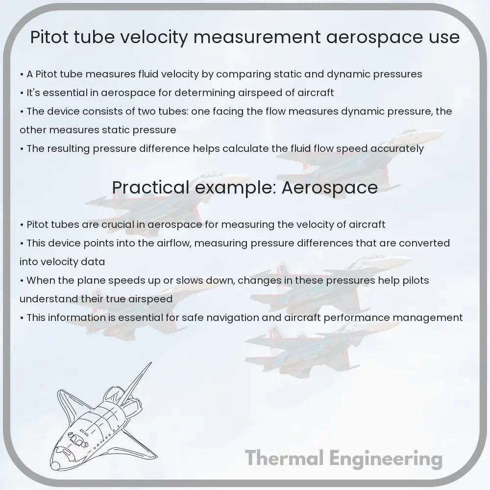
The Pitot tube is an essential device used in the field of aerospace engineering for measuring fluid velocity. Invented by the French engineer Henri Pitot in the early 18th century, the technology has evolved considerably but the basic principles remain largely unchanged. Today, it is most commonly seen on the exterior of aircraft and boats, where it serves as a critical component in measuring airspeed and navigational control.

How Does a Pitot Tube Work?

At its core, a Pitot tube measures fluid velocity by converting the kinetic energy of the flow into potential pressure. It consists of a tube pointing directly into the fluid flow; as the fluid enters the tube, it is brought to a rest, or stagnates, leading to an increase in pressure. This pressure, known as stagnation pressure, is then compared to the static pressure of the fluid to determine the velocity.

Essentially, the Pitot tube works based on Bernoulli’s Principle, which states that an increase in the speed of a fluid occurs simultaneously with a decrease in pressure or a decrease in the fluid’s potential energy. The fluid velocity can be quantified using the equation:

v = sqrt(2 * (P0 – P) / ρ)

Where:

  • v is the fluid velocity,
  • P0 is the stagnation pressure,
  • P is the static pressure, and
  • ρ is the fluid density.

Applications in Aerospace

In aerospace, Pitot tubes are primarily used for measuring the airspeed of aircraft. This is critical not only for safe operation but also for efficiency and performance monitoring. Airspeed indicators linked to Pitot tubes provide pilots with essential information to help make real-time decisions regarding altitude, speed, and aircraft handling.

A Pitot-static system combines the functions of the Pitot tube and static ports. While the Pitot tube measures the dynamic pressure of the airflow, the static ports measure the ambient air pressure. This combination allows for more accurate calculations of various flight parameters including airspeed, altitude, and vertical speed.

Challenges and Considerations

While the Pitot tube is a reliable instrument, it is not without its challenges and limitations. One of the primary concerns in its use is the potential for blockage. Ice, insects, or other debris can block the tube, leading to inaccurate readings or failure. Modern aircraft are equipped with systems to heat the Pitot tubes to prevent icing.

Accuracy can also be affected by the placement of the tube. Incorrect placement where air flow is turbulent or disrupted can lead to erroneous readings. Engineers must meticulously consider the location and exposure of Pitot tubes when designing and maintaining aircraft.

Conclusion

Despite its simplicity, the Pitot tube is a fundamental instrument in aerospace engineering, providing critical data for safe and efficient air navigation. Continued improvements in design and technology are enhancing the reliability and accuracy of this important tool, ensuring its role in aerospace for years to come.

Orifice Plate | Flow Restriction, Measurement

Learn about orifice plates, crucial for measuring and controlling fluid flow in pipelines using principles of fluid dynamics.

Orifice Plate | Flow Restriction, Measurement

Understanding Orifice Plates: Principles of Flow Restriction and Measurement

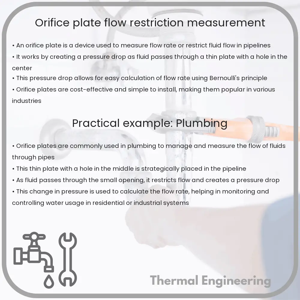
Orifice plates are simple yet essential devices used in fluid mechanics to measure flow rates and control or restrict fluid flow in pipelines. These devices function based on basic principles of physics and engineering, specifically Bernoulli’s equation and the continuity equation.

What is an Orifice Plate?

An orifice plate is a thin plate typically made of metal with a precise, sharp-edged hole drilled in it. It is installed in a pipeline and acts to constrict the flow of fluid (liquid or gas), causing a pressure drop across the plate. The characteristics of the orifice plate, such as the diameter of the hole and the thickness of the plate, significantly influence the flow and pressure drop, making it vital to calibrate them accurately for specific applications.

How Does an Orifice Plate Measure Flow Rates?

The operation of an orifice plate is based on two fundamental fluid dynamics equations:

  • Bernoulli’s Equation: This principle implies that an increase in the speed of a fluid occurs simultaneously with a decrease in pressure or a decrease in the fluid’s potential energy.
  • Continuity Equation: It asserts that the mass flow rate has to remain constant from one cross-section of a pipe to another, providing the flow is steady and the fluid is incompressible.

As fluid enters the orifice plate, it is forced to converge through the smaller hole, increasing its velocity and decreasing its pressure. This phenomenon is referred to as the “vena contracta” – the point where the stream diameter is at its smallest and the velocity is at its highest.

The basic equation used to determine the flow rate through an orifice plate can be expressed as:

\[ Q = C * A * \sqrt{\frac{2 * \Delta P}{\rho}} \]

  • Q is the flow rate,
  • C is the discharge coefficient, which accounts for the energy loss due to friction and the contraction of the stream,
  • A is the area of the orifice,
  • ∆P is the pressure drop across the orifice,
  • ρ is the density of the fluid.

This equation highlights the direct relationship between the flow rate and the square root of the pressure differential, making it clear why measuring the pressure drop allows for the determination of the flow rate.

Applications and Benefits of Orifice Plates

Orifice plates are widely used across various industries including oil and gas, water treatment, and chemical processing because they are economical, easy to install, and applicable to a wide range of fluid types. Their benefits include:

  1. Simplicity: Orifice plates are simple and have no moving parts, making them reliable and low maintenance.
  2. Cost-effectiveness: They are less expensive than most other flow meters and control devices.
  3. Versatility: They can be used in a wide range of fluid flow conditions and temperatures.

The versatile nature and practicality of orifice plates in measuring and controlling fluid flow make them an indispensable tool in the field of hydraulic and pneumatic engineering. Understanding how they work offers insights into broader principles of fluid dynamics and engineering design.

Thermal conductivity enhancement in composites

Explore the methods and importance of enhancing thermal conductivity in composites for various industrial applications.

Thermal conductivity enhancement in composites

Understanding Thermal Conductivity Enhancement in Composites

Thermal conductivity is a fundamental property of materials that measures the ability to conduct heat. In the world of materials science and engineering, enhancing the thermal conductivity of composites is crucial for a variety of applications, from heat sinks and thermal interface materials in electronics to aerospace components and automotive parts. Composites, by their nature, are materials made from two or more constituent materials with significantly different physical or chemical properties. When combined, they produce a material with characteristics different from the individual components.

Basics of Thermal Conductivity in Composites

The thermal conductivity of a composite material depends not only on the conductivities of the constituent materials but also on their proportions, the structure of the composite, and the interface characteristics between different phases. Commonly, composites are designed to enhance specific properties including mechanical strength, thermal stability, and thermal conductivity.

For example, adding high thermal conductivity fillers like copper, aluminum, or carbon fibers to a polymer matrix can significantly enhance the thermal conductivity of the resulting composite. The overall effectiveness of this enhancement depends on several factors:

  • The volume fraction of the conductive filler
  • The distribution and alignment of the filler material within the matrix
  • The thermal conductivity contrast between the matrix and the filler
  • The quality of the thermal contact at the interface between the matrix and the filler

Strategies for Enhancing Thermal Conductivity

To achieve higher thermal conductivities, engineers employ various strategies such as:

  1. Maximizing Filler Conductivity: Using fillers with intrinsically high thermal conductivity.
  2. Improving Interface Quality: Enhancing the interface thermal contact through surface treatments and the use of coupling agents.
  3. Optimizing Filler Distribution and Alignment: Ensuring an even distribution and proper alignment of fillers to form effective heat-conducting pathways throughout the matrix.
  4. Increasing Filler Content: Increasing the proportion of thermally conductive filler in the composite, up to the point where it optimizes the percolation threshold for conductivity enhancement.

Each of these strategies brings its own set of challenges and trade-offs, particularly in terms of processing techniques, cost implications, and impacts on other material properties such as mechanical strength and durability.

Case Studies and Applications

Recent advances in materials engineering have led to the development of composites with significantly enhanced thermal properties. For example, polymer composites with carbon nanotubes or graphene fillers have shown exceptional increases in thermal conductivity because these materials combine ultra-high conductivity with unique structural and surface characteristics.

In the electronics industry, thermally conductive composites are used for heat sinks and thermal interface materials to help manage the heat generated by components. In automotive applications, these composites contribute to efficient thermal management systems that enhance vehicle performance and longevity.

Future Directions

As technology advances, the demand for materials with superior thermal management capabilities continues to rise. Future research in thermal conductivity enhancement in composites is likely to focus on nanoscale engineering of components, the development of hybrid composites that synergistically utilize different conductive fillers, and the exploration of novel polymers with inherently higher thermal conductivities.

Furthermore, advancements in fabrication methods such as 3D printing and self-assembly techniques will open new possibilities for designing and manufacturing custom-tailored composites that meet specific thermal conductivity requirements for a wide range of applications.

Conclusion

Enhancing the thermal conductivity of composites plays a crucial role in the design of more efficient and durable materials for modern technological applications. By understanding and manipulating the interplay of material components at the microscopic level, engineers and scientists can continue to push the boundaries in materials science, leading to breakthroughs in electronics, automotive, aerospace, and many other critical sectors.

Francis Turbine | Efficiency, Hydropower Stations

Learn about the Francis turbine, its design, efficiency, and pivotal role in hydropower stations for sustainable energy generation.

Francis Turbine | Efficiency, Hydropower Stations

Understanding the Francis Turbine: Efficiency and Application in Hydropower Stations

The Francis turbine is a type of water turbine that was developed by James B. Francis in the mid-19th century. It is an inward-flow reaction turbine that combines radial and axial flow concepts, making it one of the most efficient turbines used in hydropower stations. This article explores the design features, efficiency aspects, and applications of the Francis turbine in generating hydroelectric power.

Design and Working Principle of Francis Turbine

Francis turbines consist of the following main parts: the spiral casing, guide vanes, runner blades, and the draft tube. Water enters the turbine through the spiral casing, which surrounds the guide vanes. These vanes direct the water flow onto the runner blades, causing the runner to spin. The water’s kinetic energy at the entrance gets converted into mechanical energy as it spins the runner. After transferring its energy, the water exits through a draft tube where the cross-sectional area gradually increases, helping to recover pressure from the kinetic energy of the flowing water.

The design of the Francis turbine allows it to operate efficiently over a wide range of flow rates and water heads, making it versatile for different power generation requirements. The efficiency of these turbines can typically range from 90% to 95% under optimal operating conditions.

Efficiency of Francis Turbines

The efficiency of a Francis turbine largely depends on its design and the conditions under which it operates. Factors such as water head, flow rate, and turbine geometry play crucial roles. The equation for hydraulic efficiency of a turbine can be expressed as:

η = Pout / Pin

Here, Pout represents the output power generated by the turbine and Pin is the power available from the water flow. In practical terms, minimizing losses due to friction, turbulence, and other mechanical inefficiencies is key to enhancing the turbine’s efficiency.

  • Friction Losses: Occur due to the resistance faced by water flowing through various components of the turbine.
  • Turbulence: Caused by improper flow angles or roughness of the surface, leading to a loss of kinetic energy.
  • Mechanical Losses: In the bearings and the generator, usually due to heat generation from moving parts.

Francis Turbines in Hydropower Stations

Francis turbines are widely used in hydropower installations worldwide. They are suitable for medium to high-head applications and can adapt to various operational requirements, such as load variation and water flow changes.

  1. They offer significant versatility and reliability for grid-connected power systems, allowing stations to adjust power output as per the demand.
  2. Their capability to operate in a reversible manner (as pump-turbines) in pumped-storage power plants makes them crucial for energy balancing, storing power during low demand and generating power during peak demand.
  3. Environmental impact is relatively controlled as modern designs emphasize fish-friendly turbines.

Conclusion

The Francis turbine continues to be a cornerstone in the field of renewable energy generation. Its design and efficiency make it ideal for a wide range of hydraulic heads and flow conditions, while advances in materials and technology have further enhanced its performance and application. Understanding these turbines’ engineering and operational mechanics provides insights into their critical role in sustainable energy solutions.

As the demand for sustainable and clean energy sources grows globally, Francis turbines play a pivotal role in meeting these needs through effective and efficient hydroelectric power generation.

Kaplan Turbine | Axial Flow, River Power

Kaplan turbines: axial flow hydro turbines optimized for low-head, high-flow water sources to efficiently generate electricity.

Kaplan Turbine | Axial Flow, River Power

Understanding Kaplan Turbines: Harnessing River Power Through Axial Flow

Kaplan turbines are a type of hydroelectric turbine that convert the energy of flowing water into mechanical energy, and subsequently electrical energy. Developed by Austrian engineer Victor Kaplan in the early 20th century, Kaplan turbines are specifically designed to operate efficiently in low-head and high-flow conditions, making them ideal for river and low-drop dam applications.

Design and Operation

The distinctive feature of Kaplan turbines is their axial flow design. In axial flow turbines, water flows in a direction parallel to the turbine shaft. The Kaplan turbine consists of several main components:

  • Runner with Adjustable Blades: The runner, or the rotating part, has blades that can be adjusted to optimize angle according to the water flow and load on the turbine, enhancing efficiency.
  • Guide Vanes: Surrounding the runner are guide vanes that direct the flow of water onto the turbine blades in an optimal manner. These vanes can also be adjusted to control the amount of water entering the turbine.
  • Draft Tube: The draft tube allows the water exiting the turbine to decelerate and recover kinetic energy, improving the overall efficiency of the turbine.

The ability of the Kaplan turbine to adjust the pitch of its blades provides a significant operational advantage. This capability allows it to maintain high efficiency over a wide range of flow rates and water levels.

Application of Kaplan Turbines

Kaplan turbines are particularly well-suited for river-based installations where the height of water (head) is relatively low and water flow is variable. Examples include:

  • River mainstream installations
  • Low-head dams
  • Tidal power stations

Their adaptability to varying flow conditions makes them an excellent choice for power generation in environments where water flow is not consistent, thereby supporting a more stable generation of energy.

Advantages of Kaplan Turbines

  • High Efficiency: Kaplan turbines maintain high efficiency across a variety of flow conditions, thanks to the adjustable blades and guide vanes.
  • Flexibility: They are capable of operating efficiently in sites with significant variations in water flow and head.
  • Low Environmental Impact: As a technology suitable for low-head applications, Kaplan turbines often do not require large dams, reducing their environmental footprint compared to other hydroelectric systems.

The Physics Behind Kaplan Turbines

The operation of Kaplan turbines can be understood through principles of fluid dynamics and energy conversion. Water enters the turbine at a certain kinetic and potential energy level, dictated by the flow rate and head. As water moves through the turbine, its energy is transferred to the rotor blades, causing them to spin. The adjustable nature of the blades allows the turbine to maximize the conversion of hydrodynamic force into rotational motion.

The rotational motion of the turbine is then used to drive a generator, converting mechanical energy into electric energy through electromagnetic induction.

Conclusion

Kaplan turbines represent a sophisticated application of fluid dynamics and mechanical engineering principles, designed to optimize energy extraction from large volumes of water at low heads. They play a crucial role in sustainable energy generation, helping to harness the renewable power of rivers with minimal environmental disruption.

As our understanding and technology evolve, further advancements in Kaplan turbine design will continue to enhance their efficiency and applicability, supporting more robust and ecologically friendly energy systems.

Positive Displacement Pump | Types, Viscosity Handling

Learn about positive displacement pumps, their types, and how they handle various fluid viscosities for industrial use.

Positive Displacement Pump | Types, Viscosity Handling

Understanding Positive Displacement Pumps

A positive displacement (PD) pump moves a fluid by repeatedly enclosing a fixed volume and moving it mechanically through the system. These pumps are capable of handling a wide variety of fluids, offering a consistent flow rate despite changes in pressure, which differentiates them from other types of pumps like centrifugal pumps. This makes PD pumps particularly useful in applications requiring precise volume control, high pressure, and the ability to handle viscous fluids.

Types of Positive Displacement Pumps

Positive displacement pumps are classified into two main categories based on their mechanism: rotary and reciprocating. Each type is suited to specific applications depending on viscosity, pressure requirements, and the nature of the fluid being pumped.

  • Rotary Pumps: These pumps use a rotating mechanism to create movement of the fluid. Common types include:
    • Gear Pumps – Two interlocking gears rotate to pump the fluid.
    • Screw Pumps – A helical screw(s) rotates to move the fluid along the axis of the screw.
    • Lobe Pumps – Similar to gear pumps but uses lobes instead of gears.
    • Vane Pumps – Uses a series of vanes in a rotor to pump fluids.
  • Reciprocating Pumps: These pumps use a back-and-forth (reciprocating) motion to move the fluid. They include:
    • Piston Pumps – A piston moves within a cylinder to push and pull the fluid.
    • Plunger Pumps – Similar to piston pumps but the seal is stationary and the plunger slides through the seal.
    • Diaphragm Pumps – Uses a flexible diaphragm instead of a piston.

Handling Viscosity in Positive Displacement Pumps

One of the primary advantages of positive displacement pumps is their ability to efficiently handle fluids with a wide range of viscosities, from thin liquids like water to thick pastes and creams. The performance of a PD pump is less affected by the viscosity of the fluid compared to other types of pumps, such as centrifugal pumps, where increased viscosity can significantly reduce performance.

Viscosity primarily affects the choice of pump type, speed of operation, and clearance between moving parts. High-viscosity fluids typically require pumps with larger clearances and lower speeds to reduce shear and maintain the integrity of the fluid. Conversely, low-viscosity fluids can be handled at higher speeds with tighter clearances for improved efficiency.

Overall, the ability of positive displacement pumps to deliver a consistent flow rate, regardless of pressure changes in the system, along with their versatility in handling different fluid viscosities, makes them indispensable in many industrial and engineering applications.

Centrifugal Pump | Operation, Design, Fluid Transport

Learn about the design, operation, and applications of centrifugal pumps, crucial for fluid transportation in various industries.

Centrifugal Pump | Operation, Design, Fluid Transport

Understanding Centrifugal Pumps

Centrifugal pumps are a subclass of dynamic axisymmetric work-absorbing turbomachinery. They are used extensively in the engineering field for the transportation of fluids through a piping system. The pump converts rotational energy, often from a motor, to energy in a moving fluid. We’ll explore the basic operation, design considerations, and applications of centrifugal pumps.

Basic Operation of Centrifugal Pumps

The primary function of a centrifugal pump is to move fluid by transferring rotational energy from one or more driven rotors, called impellers. The fluid enters the pump impeller along or near to the rotating axis and is accelerated by the impeller, flowing radially outward into a diffuser or volute chamber, from where it exits.

During operation, as the impeller rotates, it imparts kinetic energy to the fluid. This kinetic energy is then partially converted to pressure energy, according to Bernoulli’s principle, allowing the fluid to be transported through the system.

  • Suction Stage: The pump sucks the fluid into the impeller along the rotational axis.
  • Discharge Stage: The fluid is propelled outward by centrifugal force into a diffuser or volute that converts the kinetic energy to pressure energy, facilitating flow.

Design and Components of Centrifugal Pumps

The design of centrifugal pumps involves several key components:

  • Impeller: The heart of the pump, which transfers energy from the motor by accelerating the fluid radially outward.
  • Casing: Contains the liquid and acts as a pressure containment vessel that directs the flow of liquid in and out of the centrifugal pump.
  • Shaft: A rod that connects to the impeller and motor, transferring rotational power to the impeller.
  • Bearings: Support the shaft, allowing it to rotate freely within the pump casing.
  • Seal: Prevents leaks between the shaft and the casing or in other places where the pump might be vulnerable to leakage.

Engineers design the centrifugal pump casing (volute or turbine-type) to ensure smooth flow of liquid within the pump and reduce the hydraulic losses.

Fluid Transport in Centrifugal Pumps

The transport of fluid in a centrifugal pump is primarily determined by the pump’s design and the system’s needs. The flow rate of a centrifugal pump can be described by the formula:

Q = A * v

  • Q is the flow rate (usually expressed in cubic meters per second)
  • A is the cross-sectional area of the pipe (m2)
  • v is the fluid velocity (m/s)

Furthermore, the performance of a centrifugal pump is often illustrated on its characteristic curve (a graph of head against flow rate). The curve provides critical information needed to match the pump to the hydraulic requirements of a system.

Applications of Centrifugal Pumps

Due to their ability to efficiently handle large volumes of liquids, centrifugal pumps are widely used across many industries:

  • Water supply: For municipal water distribution, sewage, fire protection systems, and irrigation.
  • Chemical and petrochemical industries: Handling volatile and corrosive fluids.
  • Food and beverage: Though specially designed hygienic pumps are used here.
  • Pharmaceuticals: Again, with the use of hygienic, often sanitary, centrifugal pumps.

The versatility and efficiency of centrifugal pumps make them preferable for many applications where safe and effective fluid transport is required.

Conclusion

Centrifugal pumps are a key component in many industrial and engineering applications, valued for their simplistic design, operational efficiency, and wide capability in fluid processing and management. Understanding their operation, design, and practical uses in fluid transport can aid in selecting the right pump for specific needs, significantly impacting system performance.

Turbine Flow Meter | Mechanism, Liquid Measurement

Learn about turbine flow meters, their functioning, components, and applications in precise liquid flow measurement.

Turbine Flow Meter | Mechanism, Liquid Measurement

Understanding Turbine Flow Meters: Mechanism and Liquid Measurement Applications

Turbine flow meters are widely used in various engineering fields for precise measurement of liquid flow. Employing a simple yet effective mechanism, these devices play a crucial role in monitoring and controlling fluid flow in sectors such as water management, oil and gas, and chemical processing. This article explores how turbine flow meters work and their applications in measuring liquid flow.

What is a Turbine Flow Meter?

A turbine flow meter is a volumetric measuring device. It consists of a rotor with blades mounted on a shaft that is placed in the line of flow. The principle behind its operation is quite straightforward: as liquid flows through the meter, it impinges on the turbine blades which then rotate. The rate of this rotation is proportional to the velocity of the fluid passing through the meter.

Key Components and Their Functions

  1. Housing: Typically made from sturdy materials like stainless steel or brass, the housing contains and protects the internal components of the flow meter.
  2. Rotor: This is the primary sensing element with blades that spin in proportion to flow rate.
  3. Shaft: The rotor is attached to a shaft, which supports the rotor and allows it to spin freely.
  4. Bearings: Bearings reduce friction and wear, aiding the smooth rotation of the rotor.
  5. Pickup Sensor: Converts the mechanical action of the rotor into an electrical signal that can be recorded or displayed. This sensor usually uses magnetic or optical sensing mechanisms.

Operating Principle

The operation of a turbine flow meter is governed by the principle of angular momentum. The flow of liquid imparts a force on the turbine blades, causing them to rotate. The speed of the rotor is directly proportional to the flow rate of the liquid. This relationship can be represented by the equation:

\[ \text{Flow rate (Q)} = k * \text{Number of rotations (N)} \]

where \( k \) is a constant that depends on the characteristics of the meter and the properties of the fluid.

Calibration and Accuracy

Calibration is crucial for ensuring accurate readings. It involves setting the meter with known flows and adjusting the measurement system to match these accurately. Factors like temperature, viscosity, and pressure of the measured fluid can affect accuracy, and thus, appropriate corrections need to be applied during calibration. Modern turbine flow meters often come with built-in compensation algorithms for these variables.

Applications in Liquid Measurement

  • Water Treatment: Turbine flow meters are used extensively to measure water flow in treatment facilities to ensure proper treatment dosages and process control.
  • Petroleum and Chemicals: In industries where precise quantification of fluid volumes is necessary, such as in the dispensing of fuels or chemical reagents, turbine flow meters provide reliable and accurate measurements.
  • Food and Beverage: These meters are also employed in food and beverage production, for applications requiring stringent monitoring of liquid ingredients.

Advantages and Limitations

The primary advantage of turbine flow meters includes their high accuracy and reliability in steady, clean, and low-viscosity fluid flow conditions. They also feature quick response times and easy installation and maintenance. However, their effectiveness can be compromised by the presence of particulate matter or high-viscosity fluids, which may cause wear or jamming of the rotor. Additionally, abrupt changes in flow rate or direction can adversely affect measurement accuracy.

In conclusion, turbine flow meters are versatile tools for the precise measurement of liquid flow. With proper installation, calibration, and maintenance, they offer effective solutions across various industries where flow measurement is critical to operations and process efficiency.

Pelton Wheel | Impulse Design, Hydro Power

Learn about the Pelton wheel, a crucial component in hydroelectric power generation, known for its efficiency and innovative design.

Pelton Wheel | Impulse Design, Hydro Power

Understanding the Pelton Wheel: A Key Component in Hydroelectric Power

The Pelton wheel, named after inventor Lester Allan Pelton in the 1870s, represents a landmark in the design of impulse water turbines used predominantly for hydroelectric power. These turbines are specifically adapted for high-head water sources and are remarkably efficient in converting the energy of falling water into mechanical energy. Understanding the basic design and functionality of the Pelton wheel can provide insights into hydroelectric power generation, one of the oldest and most important forms of renewable energy.

Design and Operation of the Pelton Wheel

The Pelton wheel is composed primarily of a circular disk with specially designed buckets around its perimeter, which capture the energy of incoming water jets. Each bucket is split down the middle by a divider, known as a splitter, which allows the water jet to be split into two equal streams. This innovative design ensures that the water jet impacts the bucket without pushing against the incoming flow, enhancing efficiency by minimizing counter-torque.

  • The bucket design is critical in controlling the speed and efficiency of the Turbine. The shape and depth of the buckets ensure that water enters smoothly, turns almost 180 degrees, and leaves with reduced speed, thus maximizing momentum transfer from the water jet to the wheel.
  • Jet nozzles control the flow of water striking the buckets. Operators can adjust the number and size of these nozzles according to power needs, which makes the Pelton wheel adaptable to varying water flow conditions.

Mathematical Implications in a Pelton Wheel System

The operation of a Pelton wheel can be analyzed using the principles of linear momentum and energy conversion. The primary equation governing the Pelton wheel’s mechanics derives from the law of conservation of momentum, explained as follows:

If v1 is the velocity of the water jet at the point of impact and v2 is the velocity of water leaving the bucket, the effective change in velocity (Δv) which is crucial for calculating turbine power, is given by:

\[ \Delta v = v_1 – (-v_2 \cos \theta) \]

where \(\theta\) is the angle at which water exits the bucket relative to its incoming direction. The ideal design ensures that \(\theta\) is close to 180 degrees, minimizing the \(-v_2 \cos \theta\) term and maximizing \(\Delta v\).

The power (P) generated by the Pelton wheel can thus be estimated using the equation:

\[ P = \frac{1}{2} \rho Q \Delta v^2 \]

where \(\rho\) is the density of water, and \(Q\) is the volumetric flow rate of the jet.

Applications of the Pelton Wheel in Hydroelectric Projects

The Pelton wheel is most effective in scenarios where water source availability is characterized by high head and low flow. Such conditions are typical in mountainous regions where steep falls are more prevalent. Key advantages include:

  • High efficiency across varying load conditions.
  • Robust and simple design, leading to lower maintenance costs compared to other turbine types.
  • Ease of integration with electrical generators due to its operational stability and good speed regulation.

In conclusion, the Pelton wheel has stood the test of time as one of the most efficient solutions for converting water energy into electrical power under specific geographical conditions. Its design optimization and engineering adjustment have allowed it to play a pivotal role in the sustainable production of hydroelectric power worldwide, demonstrating a compelling example of how classical engineering concepts continue to impact modern technology.