Facebook Instagram Youtube Twitter

How does a thermal power station generate electricity

Learn how thermal power stations convert heat into electricity using coal, oil, or gas, detailing their operation, efficiency, and environmental impact.

How does a thermal power station generate electricity

Introduction to Thermal Power Stations

Thermal power stations are pivotal in meeting the electricity demands of large populations and industries around the world. These power plants generate electricity by converting heat energy into electrical energy, primarily using coal, natural gas, or oil as fuel. This article explores how a thermal power station functions, detailing each step of the process from fuel burning to electricity generation.

Basic Principle

The fundamental principle behind a thermal power station is the conversion of thermal energy to mechanical energy, and finally to electrical energy. This process involves several core components including the boiler, turbine, generator, and cooling system.

Step-by-Step Electricity Generation Process

  • Fuel burning: Energy production begins in the furnace, where fuel (typically coal, oil, or natural gas) is burnt to generate heat. This heat is used to raise the temperature of water in the boiler, transforming it into steam.
  • Steam generation: In the boiler, high pressure is used to convert the water into high-pressure steam. This high-pressure steam possesses both heat energy and kinetic energy.
  • Steam turbine: The high-pressure steam from the boiler is directed to a steam turbine where it expands and cools. This expansion under high pressure drives the turbine blades to rotate, converting thermal energy into mechanical energy.
  • Electric generator: The rotating turbine is connected to a generator. As the turbine blades turn, they spin a rotor inside the generator. This rotor, equipped with magnets, rotates within a coil of wire, producing electricity through electromagnetic induction.
  • Cooling and condensation: After the steam has passed through the turbine, it needs to be cooled and condensed back into water. This cooled water is recycled back to the boiler where it can be heated again, creating a closed loop. Cooling is usually achieved with the help of a cooling tower and a condenser.
  • Power distribution: Electricity generated is then stepped up in voltage through a transformer and transmitted via power lines for distribution to homes, industries, and businesses.

Efficiency and Environmental Impact

Thermal power stations are efficient in terms of energy output, but they also have significant environmental impacts, primarily due to the burning of fossil fuels. They produce large amounts of carbon dioxide—a major greenhouse gas—along with other pollutants. Continuous efforts are made to improve the efficiency of these power plants and to reduce their environmental footprint through the adoption of cleaner technologies and various pollution control measures.

Conclusion

Thermal power stations play a crucial role in modern energy production, providing a significant portion of the world’s electricity supply. Understanding the operational mechanics of these plants helps in appreciating how energy is produced and the challenges associated with its generation and environmental management. Although essential, these plants also highlight the ongoing need for sustainable and cleaner energy alternatives.

How does a reciprocating compressor compress gas

Learn how a reciprocating compressor compresses gas in systems like refrigeration and HVAC through a detailed explanation of its components and operation cycle.

How does a reciprocating compressor compress gas

Understanding How a Reciprocating Compressor Works

A reciprocating compressor, often used in refrigeration and air conditioning systems, compresses gas with the help of a piston moving in a cylinder through the mechanics of a crankshaft and a connecting rod. This type of compressor is known for its ability to achieve high pressures, which is suitable for various industrial applications. Let’s explore the process in more detail.

Components of a Reciprocating Compressor

  • Piston: Moves back and forth inside the cylinder.
  • Cylinder: Houses the piston and controls the flow of gas.
  • Crankshaft: Converts rotational motion into linear motion.
  • Connecting Rod: Connects the piston to the crankshaft.
  • Valve: Regulates gas entry and exit from the cylinder.

The Compression Cycle

The compression of gas in a reciprocating compressor follows these major steps:

  1. Suction Stroke: As the piston moves downwards, it creates a vacuum in the cylinder above it. The inlet valve opens due to the pressure difference, allowing the refrigerant gas to enter the cylinder.
  2. Compression Stroke: The inlet valve closes, and the piston starts moving upwards. The gas in the cylinder is compressed by the decreasing volume caused by the piston’s upward movement. This increase in pressure and decrease in volume follow the relation PVn = C, where P is pressure, V is volume, and C is a constant, while n depends on the type of gas.
  3. Discharge Stroke: Once the gas reaches a sufficient pressure that exceeds the pressure in the discharge line, the discharge valve opens, and the compressed gas is forced out into the refrigeration system or storage tank.

Energy Transformations

The primary energy transformation in a reciprocating compressor is from mechanical energy into pressure energy of the gas. The mechanical energy is supplied by the motor which rotates the crankshaft. This rotational motion is translated into linear motion of the piston via the connecting rod, leading to the compression of the gas.

Key Factors Affecting Performance

The efficiency and performance of a reciprocating compressor can be influenced by several factors:

  • Clearance Volume: The volume within the cylinder that is not swept by the piston affects the capacity of the compressor to fully discharge the compressed gas, impacting efficiency.
  • Piston Displacement: Represents the actual volume of gas taken in and compressed per stroke of the piston. Higher displacement can mean a higher capacity compressor.
  • Maintenance: Regular maintenance such as checking the tightness of the seals, ensuring the valves are functioning properly, and lubricating moving parts is crucial to maintaining the performance and extending the life of a compressor.

Applications

Reciprocating compressors are widely used in various applications where high pressures are required. These include:

  • Refrigeration and HVAC systems
  • Gas pipelines
  • Oil refineries
  • Chemical plants

In conclusion, the reciprocating compressor plays a vital role in numerous industrial and commercial settings by efficiently compressing gases into smaller volumes at higher pressures. Understanding how it works helps in optimizing its usage and maintaining its operation over time.

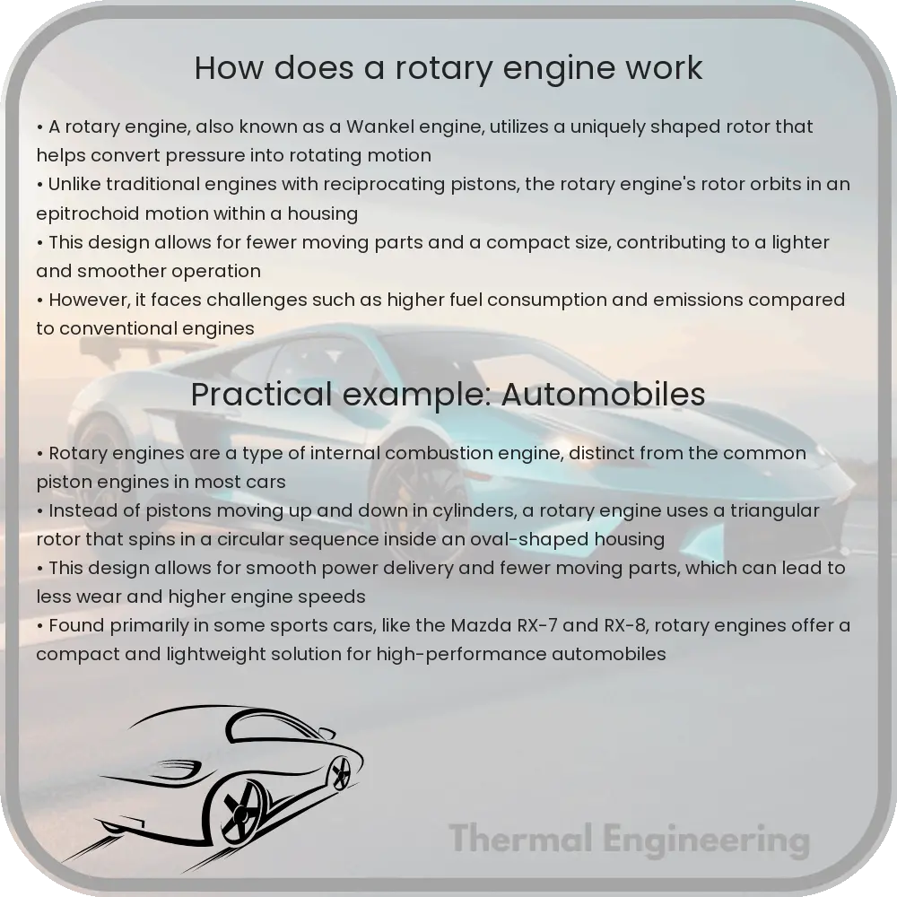
How does a rotary engine work

A comprehensive guide to the rotary engine, exploring its unique design, operation, and how it differs from traditional piston engines.

How does a rotary engine work

Understanding the Rotary Engine

The rotary engine, also known as the Wankel engine, is a type of internal combustion engine that stands out for its unique design and mechanism of operation. Unlike the more common reciprocating piston engines, the rotary engine utilizes a radically different geometric approach to convert pressure into rotating motion. Here’s a deep dive into how rotary engines work and what makes them distinct.

Basic Working Principle

The heart of the rotary engine is the rotor, which rotates inside an epitrochoidal-shaped housing. The basic operation of a rotary engine involves three main processes: intake, compression, ignition, and exhaust. Each of these processes occurs in separate sections of the engine housing as the rotor rotates. Unlike piston engines which use the linear motion of pistons, the rotary engine uses the eccentric rotation of the rotor.

Components of the Rotary Engine

  • Rotor: The triangular-shaped rotor replaces the conventional pistons. It rotates around an eccentric shaft and has three convex faces, each serving as a combustion chamber.
  • Housing: The epitrochoidal or oval-like shape of the housing is designed to maintain contact with the rotor’s faces throughout each rotation cycle. To picture this shape, imagine a rounded triangle with sides that bulge outward.
  • Intake and exhaust ports: These are located on the engine housing. The intake port allows the air-fuel mixture into the engine, and the exhaust port lets out the combustion gases.
  • Spark plugs: Typically, there are two spark plugs per rotor, which are vital for igniting the air-fuel mixture in the combustion chambers.

Operation Cycle of a Rotary Engine

  1. Intake: As the rotor moves past the intake port, a mixture of air and fuel enters the combustion chamber formed between one face of the rotor and the housing.
  2. Compression: As the rotor continues to turn, the volume of the chamber decreases, compressing the air-fuel mixture. This movement brings the apex of the rotor closer to the spark plugs.
  3. Ignition: Once the air-fuel mixture is sufficiently compressed, the spark plugs ignite it, causing combustion. The force of combustion pushes the rotor, causing it to turn and produce power.
  4. Exhaust: As the rotor continues to rotate, the exhaust gases are pushed out of the chamber through the exhaust port when it aligns with it.

Advantages and Disadvantages of Rotary Engines

Rotary engines are admired for several advantages:

  • Smooth Operation: Their design allows for fewer moving parts, which generally results in smoother operation compared to piston engines.
  • Compact Size: They tend to be smaller and lighter than traditional engines with equivalent power outputs.
  • High Power-to-Weight Ratio: Rotary engines can deliver more power relative to their weight, a characteristic beneficial in sports cars and aircraft.

However, there are some disadvantages:

  • Fuel Consumption: They tend to have poorer fuel efficiency and higher emissions compared to piston engines.
  • Wear and Tear: The rotor and housing are subject to wear due to the high-speed contact, requiring more frequent maintenance.

Conclusion

The rotary engine, with its innovative design, offers a different approach to generating power in vehicles and other machinery. While it has not become as widespread as the piston engine, its unique advantages make it particularly valuable for specific applications where size, weight, and smooth operation are crucial. Understanding the mechanisms behind the rotary engine provides an impressive glimpse into the variety of solutions engineering can offer to everyday challenges.

How does an axial flow pump move fluid

Learn how axial flow pumps, also known as propeller pumps, efficiently move fluids using a propeller-like impeller in a direction parallel to the shaft.

How does an axial flow pump move fluid

Understanding the Functioning of Axial Flow Pumps

An axial flow pump, often referred to as a propeller pump, utilizes a propeller-like impeller to move fluid in a direction parallel to the impeller shaft. This type of pump is distinguished by its cylindrical shape and the way in which it induces flow along the axis of the impeller. In this article, we’ll explore the basic mechanics behind how axial flow pumps operate, their design features, and typical applications.

Basic Principle of Operation

The core operation of an axial flow pump revolves around its central component, the impeller, which is mounted on a shaft and positioned within a tube. As the impeller rotates, it pushes the fluid in the direction parallel to the shaft. Unlike centrifugal pumps, which move fluid perpendicular to the shaft, axial flow pumps operate more like a fan or propeller.

The energy transfer to the fluid occurs through the impeller blades, which are designed to push the fluid in a streamlined direction. The fluid enters the pump in an axial direction and is pressurized as it passes through the impeller, exiting the pump in the same direction but at a higher velocity and pressure.

Design Characteristics

Axial flow pumps are known for their simple design, which typically includes fewer moving parts than other pump types, leading to reduced maintenance needs. Key components of an axial flow pump include:

  • Impeller: Equipped with several blades, it is the primary part responsible for fluid movement.
  • Shaft: Supports the impeller and connects to the drive mechanism.
  • Tubular casing: Houses the impeller and helps direct the flow of the fluid.
  • Suction and discharge ports: Located at either end of the pump for fluid ingress and egress.

The impeller blades are usually adjustable, allowing for flexibility in the flow rate and head pressure without changing the speed of the impeller. This feature is particularly useful in applications requiring variable flow conditions.

Key Performance Equations

The performance of an axial flow pump can be assessed based on several key parameters which are expressed by the following equations:

The flow rate \( Q \) of the pump is influenced by the impeller speed (\( n \)), the impeller diameter (\( D \)), and the fluid flow velocity (\( v \)):
\[ Q = \pi * D^2 / 4 * v \] where \( \pi \) (pi) is a mathematical constant, \( D \) is the diameter, and \( v \) is the velocity of the fluid.

The pressure rise (\( \Delta P \)) across the pump is related to the fluid density (\( \rho \)), the square of the velocity (\( v^2 \)), and a pressure coefficient (\( C_p \)), which depends on the pump and impeller design:
\[ \Delta P = \rho * C_p * v^2 / 2 \] where \( \rho \) is the density of the fluid and \( C_p \) is a variable dependent on various factors including the blade angle and spacing.

Applications of Axial Flow Pumps

Axial flow pumps are typically used in applications requiring large volumes of fluid to be moved at relatively low pressure. Some common applications include:

  • Flood control: Used for large-scale dewatering and water level management.
  • Water parks: Helps in creating river-like flows and other water features.
  • Agricultural irrigation: Ideal for distributing large volumes of water over wide areas.
  • Chemical processing: Useful in handling large volumes of chemicals at controlled flow rates.

Understanding the basic operation and components of axial flow pumps provides insights into their versatility and suitability for specific applications. With their ability to handle large volumes of fluid, axial flow pumps play a critical role in various industrial and environmental processes.

Cooling load calculations in buildings

Learn about cooling load calculations, a crucial process in designing efficient HVAC systems for maintaining indoor comfort in buildings.

Cooling load calculations in buildings

Understanding Cooling Load Calculations in Buildings

Cooling load calculations are crucial in the design and operation of efficient air conditioning systems in buildings. These calculations help engineers determine the amount of heat that needs to be removed from a building to maintain a comfortable indoor environment. This process is vital to ensure that the HVAC (Heating, Ventilation, and Air Conditioning) systems are appropriate for the space they serve, optimizing energy consumption and enhancing occupant comfort.

Factors Influencing Cooling Loads

The cooling load of a building is influenced by various factors, both external and internal. Understanding these factors allows engineers to estimate cooling requirements accurately:

  • External Heat Gains: Sunlight through windows, external air temperature, and humidity levels can significantly impact the internal temperature of a building.
  • Internal Heat Gains: Heat emitted from occupants, electronic devices, lighting, and machinery also contribute to the cooling load.
  • Building Material and Construction: The thermal properties of building materials and the quality of construction (such as insulation and air leakage) affect how heat is transferred into and retained within the building.
  • Occupancy: The number of people using the building and their activity levels influence the internal heat gain and thus the cooling load.
  • Geographical Location: Buildings in hotter climates or areas with high solar radiation require more significant cooling efforts compared to those in cooler climates.

Methods for Calculating Cooling Loads

There are primarily two methods used to calculate cooling loads in buildings: the CLTD/CLF/SCL (Cooling Load Temperature Difference/Cooling Load Factor/Solar Cooling Load) method and the Heat Balance Method (HBM). Each has its applications, advantages, and complexity.

  1. CLTD/CLF/SCL Method: This is a simplified method suitable for quick, preliminary calculations and is generally used in smaller or less complex installations. It involves adjusting tabulated values for temperature differences, cooling load factors, and solar radiation to tailor them to the specific conditions of the building.
  2. Heat Balance Method (HBM): This method is more comprehensive and involves detailed calculations that account for the dynamic interactions between different heat gains and the building mass. HBM is typically used for larger and more complex buildings, requiring a more detailed consideration of thermal interactions.

Equations and Calculations

The basic equation used in cooling load calculations is a form of the energy balance equation, which can be stated as:

Qtotal = Qgain – Qloss

Where:

  • Qtotal is the total cooling load,
  • Qgain is the heat gained internally and externally, and
  • Qloss is the heat lost.

In practical applications, sophisticated software is often used to perform these calculations by simulating various scenarios and accounting for all the variables involved. Accurate cooling load calculations consider transient heat gains and losses, varying occupancy, and operating schedules, which are crucial for energy-efficient building design.

Importance of Accurate Cooling Load Calculations

Accurate cooling load calculations are imperative for several reasons:

  • System Efficiency: Proper sizing of HVAC systems ensures operational efficiency, reducing energy consumption and the environmental impact.
  • Cost Effectiveness: Oversized systems are more expensive and consume more energy than necessary, while undersized systems may not maintain comfort during peak loads.
  • Comfort: Adequately calculated cooling loads ensure that the indoor environment remains comfortable for occupants, regardless of external weather conditions.
  • Environmental Impact: Efficient systems help in reducing the carbon footprint of a building by minimizing unnecessary energy use.

Understanding cooling load calculations is a fundamental aspect of HVAC design and is critical for engineers, architects, and builders aiming to create efficient and sustainable buildings.

How does an orifice plate measure flow rate

Learn how an orifice plate measures flow rates in pipelines by leveraging the principles of fluid dynamics such as Bernoulli’s and Continuity equations.

How does an orifice plate measure flow rate

Understanding How an Orifice Plate Measures Flow Rate

An orifice plate is a simple yet essential device used in engineering to measure the flow rate of liquids and gases in a pipeline. It operates based on principles from fluid mechanics, specifically Bernoulli’s equation and the Continuity equation. This article explains how an orifice plate functions and how it uses these principles to determine flow rate.

The Basics of Orifice Plate Design

An orifice plate is typically a thin plate with a precisely measured hole drilled in the center. It is installed in a pipe system, and as fluid reaches the plate, the hole forces the fluid to constrict as it passes through, creating a pressure drop from one side of the plate to the other. The size of the hole in the orifice plate is smaller than the diameter of the pipe, which is a critical aspect of its design.

Measurement Principle:

The principle behind the measurement of flow rate using an orifice plate draws from two fundamental equations in fluid dynamics:

  • Bernoulli’s Equation: This equation describes the conservation of energy in a flowing fluid and is expressed as:

P1 + 1/2 ρv12 + ρgh1 = P2 + 1/2 ρv22 + ρgh2

where P is the pressure, ρ (rho) is the density of the fluid, v is the velocity of the fluid, g is the acceleration due to gravity, and h is the height of the fluid column. Subscripts 1 and 2 represent conditions at two different points along the pipe, before and after the orifice plate.

  • Continuity Equation: This equation states that in a closed system, the mass flow rate must be constant throughout the system:

A1v1 = A2v2

where A represents the cross-sectional area of the pipe and v is the velocity of the fluid at locations 1 and 2.

Applying The Principles

When the fluid passes through the smaller opening of the orifice plate, its velocity increases, and according to Bernoulli’s principle, the pressure decreases. This differential pressure (ΔP = P1 – P2) created across the orifice plate is measured using pressure sensors installed before and after the orifice.

The increase in velocity and the corresponding pressure drop are key to calculating the flow rate. By rearranging the Continuity and Bernoulli equations, engineers can derive the flow rate (Q) as follows:

Q = C * A2 * √(2ΔP / ρ)

where C is the discharge coefficient, which accounts for energy losses and can vary based on the geometry of the orifice plate and the properties of the fluid. A2 is the area of the orifice, and ρ is the fluid density.

Real-World Applications

Orifice plates are widely used in various industries, including oil and gas, water treatment, and chemical processing, due to their simplicity, reliability, and cost-effectiveness. They are particularly useful in applications where a robust and straightforward method for flow measurement is required.

Conclusion

The orifice plate is a fundamental tool in the field of engineering, providing critical data for the efficient management and operation of fluid systems. By understanding how it operates through the principles of fluid dynamics, engineers are able to design more effective and efficient systems. The technology behind orifice plates exemplifies how basic physical laws can be applied to solve practical, everyday engineering challenges.

How does a turbocharger increase engine power

Learn how a turbocharger boosts engine power by compressing air for more efficient fuel combustion, enhancing vehicle performance.

How does a turbocharger increase engine power

Understanding How a Turbocharger Increases Engine Power

Ever wondered how some engines, particularly in smaller cars or performance vehicles, can deliver such impressive power? One key component that helps achieve this is the turbocharger. Turbocharging is an engineering marvel that allows engines to produce more power, which ultimately enhances the vehicle’s performance. Here’s a simple explanation of how a turbocharger works and its impact on engine power.

What is a Turbocharger?

A turbocharger is a turbine-driven forced induction device that increases an internal combustion engine’s efficiency and power output by forcing extra compressed air into the combustion chamber. The basic principle behind a turbocharger is to use the engine’s exhaust gases to drive a turbine, which then drives a compressor, compressing ambient air and delivering it at a higher pressure to the engine. This allows the engine to burn more fuel per second, thus increasing power.

The Components of a Turbocharger

  • Turbine: This component harnesses the energy from the exhaust gases exiting the engine. The gases enter the turbine housing, hit the turbine wheel, and cause it to spin.
  • Compressor: Connected to the turbine by a shaft, the compressor draws in ambient air, compresses it, and then sends the highly compressed air to the engine’s intake. Compressing air increases its oxygen density, enabling more fuel combustion than would normally be possible.
  • Intercooler: Often used in conjunction with a turbocharger, the intercooler is a type of radiator that cools the compressed air before it enters the engine. Cooling the air helps increase its density even further, which enhances combustion.

How Turbocharging Increases Engine Power

The core goal of a turbocharger is to improve the engine’s efficiency and power without increasing its weight. By compressing the air, more air molecules (and therefore more oxygen) are forced into the combustion chamber. When there is more oxygen available, the engine can burn more fuel. The equation for the combustion process can be briefly described as follows:

More oxygen + More fuel = More power

This process is particularly effective because it utilizes the exhaust gas that would otherwise be wasted energy. In simple terms:

  1. Exhaust gases from the engine enter the turbocharger turbine.
  2. The turbine spins and powers the compressor.
  3. The compressor draws in and compresses ambient air, then pushes it into the engine’s air intake.
  4. Compressed air allows the engine to burn more fuel efficiently.
  5. Increased combustion results in higher output power from the engine.

Benefits and Considerations

While turbochargers can significantly increase power and efficiency, they also come with considerations. Turbocharged engines might face increased engine temperature and need robust materials that can withstand higher pressures and temperatures. Furthermore, there can be a slight delay between demanding power from the engine and the turbocharger responding, known as “turbo lag”. Advances in technology and design continue to mitigate these effects, improving responsiveness and efficiency.

In conclusion, a turbocharger is a powerful tool for boosting engine performance. By reusing exhaust gas energy to compress air, it allows for more intense combustion, translating into increased power output without the need for a larger engine. As automotive technologies evolve, the integration and efficiency of turbochargers are only likely to improve, continuing to play a crucial role in enhancing engine performance across various applications.

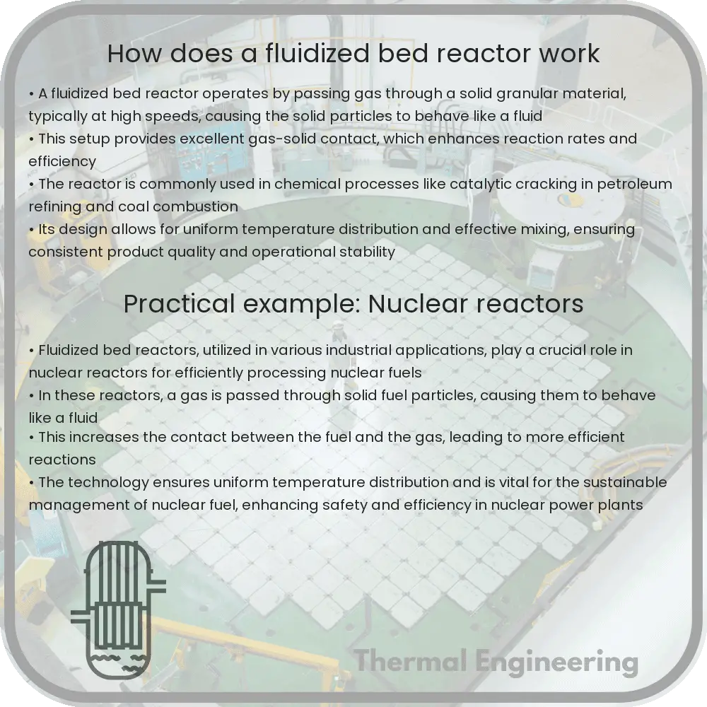
How does a fluidized bed reactor work

Explore the functionality and applications of fluidized bed reactors, key devices in enhancing reaction rates and efficiency in various industries.

How does a fluidized bed reactor work

Understanding Fluidized Bed Reactors

Fluidized bed reactors are remarkable engineering devices primarily used in chemical processes and in the energy industry. They facilitate improved reaction rates and high efficiency thanks, in part, to their superior heat and mass transfer characteristics. This technology can be found in settings ranging from fossil fuel processing to waste treatment facilities and is crucial in the manufacture of various chemicals and materials.

Principle of Operation

At its core, a fluidized bed reactor operates by suspending solid particles in an upward-flowing stream of fluid, typically gas or air. This suspension process is referred to as “fluidization. When the fluid velocity is sufficient to balance the gravitational force on the particles, they become suspended, creating a fluid-like state. The bed of solid particles is said to be “fluidized,” exhibiting properties akin to both solids and liquids.

The Fluidization Process

Fluidization is achieved when the upward drag force from the flowing fluid equals the gravitational force pulling the particles downward. This condition is quantified by the dimensionless numbers like Reynolds number and minimum fluidization velocity. At this critical point, particles begin to bubble and move vigorously within the reactor, promoting high-contact efficiency between the phases.

Advantages of Fluidized Bed Reactors

  • High Efficiency: Fluidized bed reactors provide excellent heat and mass transfer. This is due to the large surface area of the particles involved and the turbulent mixing within the bed.
  • Uniform Particle Mixing: Due to the fluid-like behavior of the bed, particles are continuously mixed. This ensures a uniform temperature and composition of the reaction mass, leading to better product consistency.
  • Temperature Control: The vigorous mixing helps in maintaining uniform and stable temperatures throughout the reactor, reducing the likelihood of hotspots which can adversely affect the reaction.
  • Scalability: These reactors are relatively easy to scale based on process needs. Adjustments to bed height and fluid velocities can accommodate different production volumes.

Common Applications

  1. Chemical Production: Synthesis of polymers and complex chemicals often employ fluidized bed reactors due to their efficiency and control over reaction conditions.
  2. Combustion and Gasification: Fluidized bed reactors are widely used for the combustion of coal and biomass, as well as in the gasification processes, due to their ability to operate efficiently with a variety of fuel types and sizes.
  3. Waste Treatment: Incineration of wastes using fluidized bed technology helps in achieving complete combustion of organic materials, turning them into ash and flue gas.
  4. Pharmaceutical Manufacturing: The precise control and high rates of heat and mass transfer make fluidized bed reactors suitable for the production of pharmaceuticals.

Challenges and Limitations

Despite their numerous benefits, fluidized bed reactors do face some challenges. These include erosion of reactor components from constant particle contact, potential for agglomeration of particles under certain conditions, and complex flow dynamics that might require sophisticated control strategies. Addressing these challenges continues to be a focus for improving reactor designs and operational techniques.

Conclusion

Fluidized bed reactors are crucial in many industrial processes due to their superior heat and mass transfer capabilities. They offer high efficiency, better control over reaction conditions, and are adaptable to a wide range of applications. Understanding the basics of how these reactors work is essential for engineers and scientists working to improve industrial processes across various sectors. By optimizing the design and operation of fluidized bed reactors, industries can achieve more efficient, sustainable, and cost-effective production cycles.

How does a pitot tube measure velocity

Learn how a pitot tube measures fluid velocity using design features and Bernoulli’s principle in engineering applications.

How does a pitot tube measure velocity

Understanding How a Pitot Tube Measures Velocity

A pitot tube is an essential tool used in various engineering disciplines to measure fluid velocity. Particularly common in aerospace and automotive engineering, this instrument plays a crucial role in measuring the speed of aircrafts and cars. But what exactly is a pitot tube, and how does it work? Let’s delve into the principles of its operation.

The Basic Design of a Pitot Tube

A pitot tube is a simple, yet ingeniously designed device, consisting of a tube that has two holes: a front hole pointed directly into the fluid flow and side holes that are exposed to the fluid but not directly in the flow. These openings are connected to a manometer, or a differential pressure gauge, which measures the difference in pressure between the two openings.

How It Works

As the fluid (air or liquid) moves, it enters the pitot tube through the front hole. The speed of the fluid causes a pressure increase inside the tube; this is known as the stagnation pressure because the fluid particles are virtually “stagnated” (brought to a stop). Meanwhile, the side holes measure the static pressure, which is the pressure of the fluid in the environment independent of the flow.

The main principle on which a pitot tube operates involves the Bernoulli Equation for incompressible fluids, which is expressed as:

\[ P + \frac{1}{2} \rho v^2 + \rho gh = \text{constant} \]

Here, \( P \) represents the static pressure, \( \rho \) the fluid density, \( v \) the fluid velocity, and \( gh \) the hydrostatic pressure term, where \( g \) is gravitational acceleration and \( h \) is the height above a reference level.

To determine the velocity \( v \) of the fluid flow, the pitot tube uses the difference between the stagnation pressure and the static pressure. The difference in pressure, known as dynamic pressure (\( q \)), is given by:

\[ q = \text{stagnation pressure} – \text{static pressure} \]

Using Bernoulli’s Principle, the dynamic pressure can also be expressed as:

\[ q = \frac{1}{2} \rho v^2 \]

From the dynamic pressure equation above, the velocity \( v \) of the fluid can be calculated using the formula:

\[ v = \sqrt{\frac{2q}{\rho}} \]

It’s crucial to consider fluid density \( \rho \), which can vary significantly, especially in gases, depending on temperature and pressure.

Applications and Limitations

Pitot tubes are widely used in environments where accurate measurements of fluid flow velocity are necessary. In aircraft, these instruments are crucial for providing pilots with real-time data on airspeed, which is vital for safe and efficient operation. Similarly, in car racing, pitot tubes help measure the speed of the car, providing valuable data for performance tuning.

However, their accuracy can be affected by several factors, such as the angle of the tube relative to the flow direction, the viscosity and turbulence of the fluid, and environmental factors like temperature and pressure changes. Engineers must calibrate and sometimes adjust pitot tube readings to account for these variables to ensure accurate velocity readings.

Conclusion

The pitot tube remains a fundamental tool in measuring fluid velocity due to its simple design and the direct applicability of Bernoulli’s principle. Understanding how it works not only emphasizes the beauty of fluid mechanics in practical applications but also illustrates the interconnectedness of physics and engineering principles in solving real-world problems.

How does a Stirling engine work

Learn about the Stirling engine, a highly efficient heat engine known for its quiet operation and versatility in using various heat sources.

How does a Stirling engine work

Understanding the Stirling Engine

The Stirling engine is a fascinating example of a heat engine that operates by cyclic compression and expansion of air or other gas (the working fluid) at different temperature levels. Invented by Rev. Robert Stirling in 1816, its main allure today comes from its ability to generate power from virtually any heat source and its reputation for being exceptionally quiet and efficient compared to other types of engines.

Basic Principles

The Stirling engine works on the principles of the Stirling cycle, which includes four main processes: isothermal expansion, isochoric (constant volume) cooling, isothermal compression, and isochoric heating. This cycle can be described as follows:

  1. Isothermal Expansion: The working gas is heated externally, causing it to expand at a constant temperature. This expansion pushes a piston outward, doing work against an external load.
  2. Isochoric Cooling: The gas undergoes a reduction in temperature at constant volume. This process typically occurs by moving the gas to a cooler part of the engine where it releases heat to the surroundings.
  3. Isothermal Compression: The cooled gas is then compressed isothermally (at a constant temperature) by an internal mechanism, which requires work to be done on the gas. This typically involves a piston moving inward.
  4. Isochoric Heating: The gas is heated again but at constant volume by moving it to a hot area of the engine or through an internal heat exchanger, preparing it for the next cycle.

Key Components

The Stirling engine consists of several key components that allow it to operate efficiently:

  • Heat Source: Provides the external heat necessary for the expansion of the working gas.
  • Heat Sink: Allows the gas to release the absorbed heat and cool down.
  • Regenerator: A crucial component, typically a porous material, that temporarily stores heat from the hot gas during the cooling phase and transfers it back during the heating phase, enhancing the engine’s efficiency.
  • Displacer: Helps in moving the working gas back and forth between the hot and cold areas in the engine.
  • Pistons: These are used to compress and expand the gas; in some designs, a single piston acts as both displacer and power piston, while others use separate pistons.

Efficiency and Applications

One of the notable advantages of the Stirling engine is its potential for high efficiency and low emissions. Theoretically, its efficiency can approach that of the Carnot cycle, the most efficient thermodynamic cycle possible for a heat engine. This efficiency makes it suitable for a variety of applications, ranging from small generators for individual use to larger power generation systems where waste heat recovery or renewable heat sources are available.

Despite its high efficiency potential, the practical use of Stirling engines has been limited by factors such as cost, complexity, and materials issues at high temperatures. However, ongoing research and development efforts continue to explore its applications in areas such as solar power generation, combined heat and power systems, and even in space exploration, where its quiet operation and reliability are highly valued.

Conclusion

The Stirling engine exemplifies a remarkable piece of engineering that showcases the application of thermodynamic principles in creating sustainable and efficient energy solutions. With advancements in technology and materials science, the potential applications of Stirling engines are expanding, promising a more energy-efficient future.