Facebook Instagram Youtube Twitter

How does phase change cooling manage heat

Learn about phase change cooling, an efficient heat management technique using the latent heat of substances during phase transitions.

How does phase change cooling manage heat

Understanding Phase Change Cooling

Phase change cooling is a highly efficient method used to manage and disperse heat in various applications, from electronic devices to industrial systems. This cooling technique exploits the heat absorption characteristics of a substance as it changes from one phase to another, typically from a solid to a liquid, or more commonly, from a liquid to a vapor.

Basic Principles of Phase Change Cooling

The foundation of phase change cooling lies in the thermodynamic process known as the latent heat of transformation. Latent heat is the amount of heat absorbed or released by a substance during a phase change, without a change in temperature. In the context of cooling systems, the most utilized phase change is the transition from liquid to gas, which absorbs a significant amount of heat, thereby cooling the surroundings.

Components of a Phase Change Cooling System

  • Evaporator: At this stage, the working fluid (commonly water or refrigerants like R134a) absorbs heat from the component to be cooled. The fluid evaporates, changing from liquid to vapor.
  • Compressor: The vapor is compressed, which increases its pressure and temperature, turning it into a superheated vapor.
  • Condenser: Here, the superheated vapor releases its heat to the environment, condenses, and turns back into a liquid.
  • Expansion valve: The liquid then passes through an expansion valve where it experiences a pressure drop, cools further, and returns to the evaporator to repeat the cycle.

Thermodynamics Behind Phase Change Cooling

Let’s dive deeper into the heat transfer equation during the phase change process:

Q = m * L

where:

  • Q is the total heat absorbed or released,
  • m is the mass of the substance,
  • L is the latent heat of vaporization (for liquid to vapor) or fusion (for solid to liquid).

For example, the latent heat of vaporization for water at 100°C is approximately 2260 kJ/kg. This means that 1 kilogram of water absorbs 2260 kJ of heat energy to convert from liquid to vapor phase at this temperature.

Applications of Phase Change Cooling

Phase change cooling has practical applications in various fields:

  • Computing: High-performance computing systems and data centers use phase change cooling to handle intense heat loads, maintaining operational stability and efficiency.
  • Electronics: Phase change materials (PCMs) are used in devices like smartphones and laptops to absorb and manage heat spikes without bulky heatsinks.
  • HVAC Systems: This cooling method is integral to refrigeration and air conditioning systems, playing a critical role in thermal management and comfort.

Advantages of Phase Change Cooling

Phase change cooling offers several benefits over traditional air cooling techniques:

  • Higher heat absorption efficiency: The use of latent heat allows for greater heat absorption capacity compared to sensible heat methods.
  • Compact system design: Due to the efficient heat transfer, cooling systems can be more compact and fit into smaller spaces.
  • Stability and control: Provides more consistent temperature control, which is crucial for sensitive electronic components and industrial processes.

In conclusion, phase change cooling represents a sophisticated approach to managing heat through the exploitation of the latent heat properties of substances. This technology not only enhances the efficiency of heat dissipation but also enables smaller and more reliable system designs, supporting advancements in numerous technological and industrial fields.
How does a heat pipe transfer heat

Explore the efficient heat transfer capabilities of heat pipes, focusing on their structure, the mechanism of heat movement, and applications.

How does a heat pipe transfer heat

Understanding Heat Pipes and Their Heat Transfer Mechanism

Heat pipes are a highly efficient type of heat transfer equipment that are used to transport heat over relatively long distances with minimal temperature drop. They are commonly found in electronics cooling, air conditioning systems, and space applications. The operation of a heat pipe is based on the principles of thermodynamics and fluid mechanics.

Basic Structure of a Heat Pipe

A heat pipe typically consists of three main components:

  • The Envelope: This is the outer shell of the heat pipe, usually made of materials with good thermal conductivity like copper or aluminum.
  • The Wick Structure: Located inside the envelope, this structure acts like a capillary pumping mechanism, transporting liquid from colder areas (the condenser) back to warmer areas (the evaporator).
  • The Working Fluid: Chosen based on the operational temperature range of the heat pipe, the fluid undergoes phase changes (evaporation and condensation) within the pipe to transfer heat.

How Heat Pipes Transfer Heat

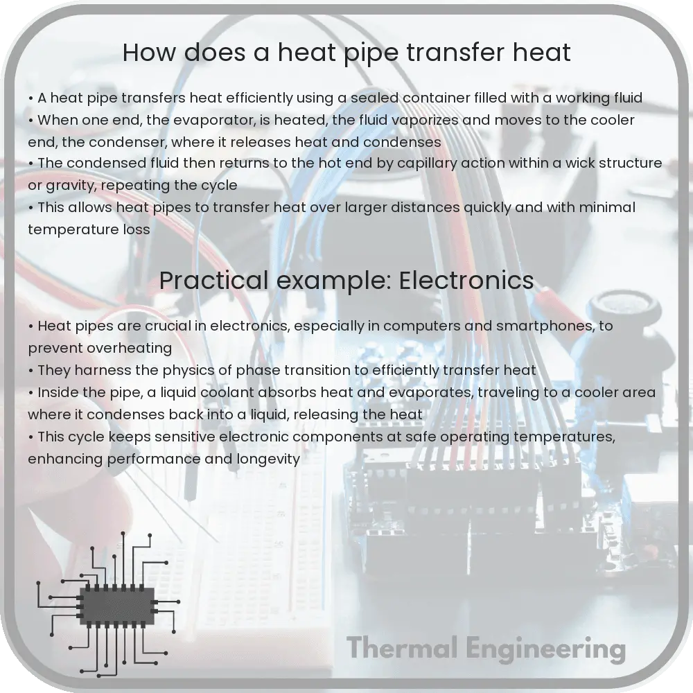
Heat pipes operate on a simple yet effective principle involving two primary physical processes: evaporation and condensation. Here’s a step-by-step explanation:

  1. Heat Absorption: At the evaporator section, which is the heat input source, working fluid inside the wick absorbs heat. This causes the fluid to evaporate, transforming from a liquid to a vapor phase.
  2. Vapor Movement: The generated vapor, which now carries the absorbed heat energy, travels through the hollow center of the heat pipe towards the cooler end known as the condenser section.
  3. Heat Release: Upon reaching the condenser, the vapor condenses back into a liquid form, releasing the transported heat to the cooler environment outside the heat pipe.
  4. Liquid Return: The condensed liquid is then drawn back to the evaporator through the wick structure by capillary action, ready to absorb more heat and restart the cycle.

The efficiency of heat pipes lies in their ability to transfer large amounts of heat with very small temperature differences between the heat source and the sink. This is primarily due to the latent heat of vaporization, which is much greater than the sensible heat capacity of the working fluid. Theoretically, the amount of heat transferred, Q, can be described by the equation:

Q = mL

where:

  • m is the mass flow rate of the vapor,
  • L is the latent heat of vaporization of the working fluid.

Applications and Advantages

Heat pipes offer several advantages over traditional heat transfer methods, including:

  • High thermal conductance,
  • Ability to transfer heat over considerable distances without substantial energy loss,
  • Uniform temperature distribution across the length of the pipe,
  • Reliability and maintenance-free operation due to the lack of moving mechanical parts.

These properties make heat pipes a valuable component in modern engineering designs, particularly where efficient heat management is crucial, such as in high-performance electronic devices, satellite technology, and renewable energy systems.

In summary, heat pipes are fascinating devices that utilize the physics of phase change and capillary action to efficiently manage heat in a variety of applications. Their ability to operate under different orientations and across varying temperature ranges while maintaining high efficiency and reliability makes them integral to modern thermal management solutions.

How does a catalytic converter reduce emissions

Learn how a catalytic converter reduces harmful vehicle emissions through oxidation and reduction reactions in exhaust systems.

How does a catalytic converter reduce emissions

Understanding How a Catalytic Converter Reduces Emissions

A catalytic converter is an essential component in the exhaust system of gasoline-powered vehicles, playing a critical role in reducing harmful emissions and protecting the environment. In this article, we will explore the basic functioning of a catalytic converter, how it helps reduce pollutants, and the chemical reactions involved in this process.

The Structure of a Catalytic Converter

A catalytic converter is typically located between the engine and the muffler on the underside of a vehicle. It looks like a small metal box attached to the exhaust pipe. Inside, it contains a core made up of a ceramic or metal structured coated with a catalyst usually made from precious metals such as platinum, palladium, and rhodium. This structure is often described as a honeycomb to maximize the surface area that interacts with exhaust gases.

How Catalytic Converters Reduce Emissions

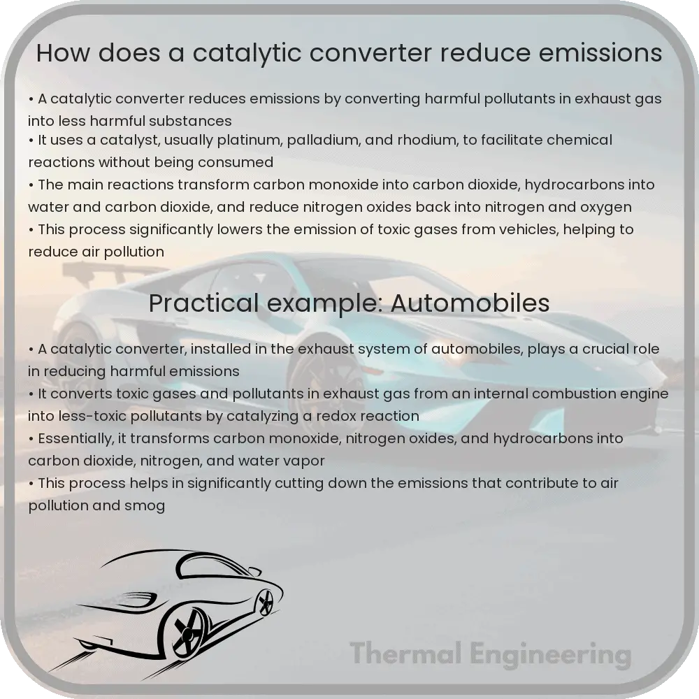
The primary function of the catalytic converter is to convert harmful pollutants into less harmful emissions before they leave the vehicle’s exhaust system. The conversion occurs through two main types of reactions facilitated by the catalyst: reduction and oxidation reactions.

  • Reduction Reactions: These reactions help reduce nitrogen oxide emissions, a major component of smog and acid rain. The catalyst promotes the breakdown of nitrogen oxides (NOx) into nitrogen (N2) and oxygen (O2), effectively reducing the amount of NOx released into the atmosphere.
  • Oxidation Reactions: These reactions target hydrocarbons (unburned fuel) and carbon monoxide (CO), which are both toxic and contribute to smog. In the presence of the catalyst, hydrocarbons are converted to carbon dioxide (CO2) and water (H2O), and carbon monoxide is converted to carbon dioxide (CO2).

Chemical Reactions Inside the Catalytic Converter

The effectiveness of a catalytic converter is largely dependent on the precise temperature and environment inside the converter. Here are the specific chemical reactions facilitated by the catalyst:

  1. Reduction of Nitrogen Oxides:

    2NOx + 2CO → N2 + 2CO2
  2. Oxidation of Carbon Monoxide:

    2CO + O2 → 2CO2
  3. Oxidation of Hydrocarbons:

    CnHm+ (n + m/4)O2 → nCO2 + (m/2)H2O

These reactions are highly efficient when the vehicle is at its optimal operating temperature and typically start to occur when the exhaust system reaches about 400 degrees Celsius (about 752 degrees Fahrenheit). This is why vehicles have higher emissions during the initial minutes after start-up, known as “cold start”.

Conclusion

Overall, the catalytic converter plays a pivotal role in reducing the environmental impact of car emissions. By converting harmful pollutants into water vapor, nitrogen, and carbon dioxide through sophisticated chemical processes, it helps meet environmental standards and contributes to cleaner air. Continuous advancements in catalytic converter technology will further enhance their ability to clean up vehicle emissions effectively.

How does a pneumatic system use air pressure

Learn about pneumatic systems, their components, and the utilization of air pressure in industrial and commercial applications.

How does a pneumatic system use air pressure

Understanding Pneumatic Systems: How Air Pressure is Used

Pneumatic systems are a crucial part of various industrial, commercial, and engineering applications. From manufacturing plants to office automation, these systems utilize compressed air to perform work, powering a wide array of equipment and processes. Understanding how pneumatic systems harness the power of air pressure can help demystify many of the tools and machines we depend on daily.

Basics of Pneumatic Systems

A pneumatic system fundamentally comprises a few key components: a compressor, reservoir, valves, actuators, and piping. The principal function of the compressor is to convert mechanical energy into pneumatic energy by compressing air. This compressed air is then stored in a reservoir or tank.

The pressurized air travels through a network of pipes to reach various pneumatic devices. Valves control the flow and direction of the air within the system, and actuators – such as cylinders and motors – convert the air pressure into mechanical motion.

How Air Pressure is Utilized in Pneumatic Systems

The operation of a pneumatic system is primarily based on the physical principle described by Boyle’s Law which states that for a given mass of compressed gas, the product of pressure and volume is a constant at constant temperature. Thus, when the volume of a chamber containing air decreases, the pressure increases.

  • Generation and Storage of Compressed Air: Air is first drawn from the atmosphere and compressed in the compressor, thereby increasing its pressure and decreasing its volume as per Boyle’s Law. This high-pressure air is stored in a tank or reservoir, ready for use.
  • Transmission Through Pipes: Compressed air travels through pipes or tubes to reach the point of use. The design of the system is crucial to minimize pressure drops due to friction and other factors.
  • Actuation: Once the compressed air reaches the actuator, it creates movement. For instance, in a pneumatic cylinder, air pressure pushes against a piston inside a cylinder, causing it to move. The movement of this piston then can be used to drive mechanical processes.
  • Control Through Valves: Valves regulate the flow and pressure within the pneumatic system by opening, closing, or partially obstructing various passageways. These are crucial for directing the flow of air efficiently and act as control points within the system.

Advantages of Using Air Pressure in Pneumatic Systems

Pneumatic systems offer several advantages which make them favorable over other types of power transmission methods like hydraulic systems. Some of these advantages include:

  • Simplicity and Cost-Effectiveness: Air, the working fluid, is abundant and inexpensive. Pneumatic systems thus require less upfront and maintenance costs.
  • Safety: Unlike hydraulic systems, which use oil, pneumatic systems pose no fire hazard since air is non-flammable.
  • Speed and Ease of Installation: Air compresses easily and rapidly allowing pneumatic systems to operate at considerable speeds. The components are also relatively straight-forward to connect and maintain.
  • Clean Operation: The use of air creates no environmental pollution issues. In the case of a leak, compressed air being clean causes little to no damage in contrast to hydraulic leaks.

In summary, pneumatic systems leverage air pressure effectively by compressing air, transferring this energy via a network of pipes and via actuators, turning pneumatic energy into mechanical work. Their simplicity, efficiency, and clean operation make them indispensable in many areas of manufacturing and automation.

Conclusion

Pneumatic systems are not just interesting from a theoretical standpoint; they offer practical engineering solutions across many applications. By understanding how these systems work, users can improve system efficiencies, troubleshoot issues, and innovate new applications for this versatile technology.

How does a Rankine cycle convert heat to work

Learn about the Rankine cycle, a key thermodynamic process in converting heat into mechanical work in power generation.

How does a Rankine cycle convert heat to work

Understanding the Rankine Cycle: Converting Heat into Work

The Rankine cycle is a fundamental concept in thermodynamics and engineering, widely used in power generation systems, particularly in thermal power plants that use steam as the working fluid. This cycle describes how heat energy is converted into mechanical work by exploiting the properties of water and steam. Here, we delve into the basics of the Rankine cycle, its components, and the science that enables this transformation from heat to work.

Main Components of the Rankine Cycle

The Rankine cycle consists of four main components:

  1. Boiler (Steam Generator): Here, water is converted into steam by applying heat energy derived from various sources such as coal, natural gas, nuclear reactions, or even concentrated solar power.
  2. Turbine: The high-pressure steam generated in the boiler is then directed to a turbine, where it expands, causing the turbine blades to spin, thus converting heat energy into mechanical work.
  3. Condenser: After losing energy in the turbine, the steam exits and is then cooled back into liquid water in the condenser. Cooling is usually achieved by a heat exchange with a separate water loop, often using water from a local body of water or a cooling tower.
  4. Feedwater Pump: The condensed liquid water, now at a lower pressure, is pumped back into the boiler by the feedwater pump, raising its pressure and completing the cycle. This pump requires external power to operate.

Thermodynamics Behind the Rankine Cycle

The Rankine cycle operates on the principle of the conservation of energy, where energy is merely transformed from one form to another without being created or destroyed. Each component of the cycle plays a crucial role in this energy transformation:

  • In the boiler, heat is added to the system, increasing the internal energy of the water and converting it into steam.
  • In the turbine, the steam’s heat energy is used to do mechanical work (rotating the turbine). The energy conversion from heat to mechanical energy primarily happens here.
  • In the condenser, the spent steam releases heat to the environment, lowering its temperature and pressure and changing it back to a liquid state.
  • The feedwater pump requires mechanical energy to increase the pressure of the condensed water and feed it back into the boiler, thus continuing the cycle efficiently.

The Efficiency of the Rankine Cycle

The efficiency of a Rankine cycle is a critical measure and is defined as the ratio of the work done by the turbine to the heat absorbed by the boiler. Mathematically, it is represented as:

\[ \text{Efficiency (}\eta\text{)} = \left( \frac{\text{Net Work Output}}{\text{Heat Input}} \right) \times 100 \% \]

Net Work Output is the difference between the turbine work output and the work required to operate the feedwater pump. The Cycle’s efficiency can be improved by increasing the temperature and pressure of the steam entering the turbine or by decreasing the temperature of the steam exiting the condenser.

Real-World Applications

The Rankine cycle is predominantly used in power generation stations, including fossil-fuel plants and nuclear power plants. It sets the backbone for the operation of these plants, providing a reliable method for converting thermal energy into electrical energy efficiently and sustainably.

By understanding these processes, engineers can design more efficient systems and contribute to more sustainable practices in energy production, reflecting the critical role that thermodynamics plays in our daily life and the environment.

In conclusion, the Rankine cycle is a vital principle in thermal power generation, showcasing how fundamental physics concepts are applied to produce substantial real-world impacts, such as electricity generation.

How does a magnetic bearing levitate

Explore the principles of magnetic levitation in magnetic bearings, focusing on their operational techniques and components for precise, contact-free support in various applications.

How does a magnetic bearing levitate

Understanding the Principles of Magnetic Levitation in Magnetic Bearings

Magnetic bearings are a sophisticated type of bearing that support moving parts without physical contact, using magnetic fields instead of traditional metal bearings. This technology finds applications in various fields, ranging from aerospace to industrial machinery, where minimal friction and no wear are crucial. The ability of a magnetic bearing to levitate an object involves complex interactions between magnetic fields, forces, and stability control systems. This article explores the fundamental principles behind magnetic levitation in magnetic bearings.

Basics of Magnetic Levitation

Magnetic levitation, or maglev, is the process by which an object is suspended in air with no support other than magnetic fields. The magnetic forces used to counteract the effects of the gravitational force and any other accelerations. This is typically achieved via one of two methods:

  • Attractive Magnetic Levitation: This method involves using magnets to attract the object towards a fixed point. It is simpler but requires active stabilization to prevent the object from attaching directly to the magnet.
  • Repulsive Magnetic Levitation: This method employs either permanent magnets or electromagnets that repel one another, thus providing the necessary levitative force without contact.

Both of these methods can be implemented in the design of magnetic bearings.

Components of Magnetic Bearings

A typical magnetic bearing system involves several key components:

  • Magnets: Either permanent magnets or electromagnets create the magnetic field necessary for levitation.
  • Sensors: Position sensors detect the real-time location of the rotor or levitated part in relation to the stator or stationary part of the bearing.
  • Control System: A feedback system which receives data from the sensors and adjusts the magnetic field accordingly to maintain stable levitation.
  • Power Amplifiers: These amplify the control signals from the control system to the electromagnets to adjust the magnetic field strength.

How Magnetic Levitation Works in Bearings

The operational principle of a magnetic bearing is to balance the magnetic forces with the gravitational force acting on the object. Here’s a closer look at the two dominant forces in magnetic bearings:

  1. Lorentz Force: This is the force exerted by the magnetic field on electrically charged particles moving through it. It is given by the equation F = q*(v × B), where F is the Lorentz force, q is the charge, v is the velocity of the charge, and B is the magnetic field.
  2. Levitating Force: This is the upward force that balances the weight of the levitated object. It must equal the gravitational force to achieve levitation, derived from Fm = m*g where Fm is the magnetic force required, m is the mass of the object, and g is the acceleration due to gravity.

By constantly adjusting the magnetic field based on feedback from sensors, the system maintains a stable levitation of the rotating shaft or object without physical contact.

Applications and Advantages

Magnetic bearings are especially useful in applications where reducing friction and avoiding physical wear are critical, such as in turbines, compressors, and high-speed trains. The elimination of friction not only reduces energy loss but also decreases heat generation and wear, leading to longer machinery life and lower maintenance costs.

The future of magnetic bearings suggests even broader applications and improvements, including enhanced levitation techniques and integration with other smart materials and technologies.

By harnessing magnetic fields, magnetic bearings provide an elegant and efficient solution for precision and longevity in mechanical operations, epitomizing the fusion of physics and engineering in practical applications.

How does an absorption chiller cool water

Learn how absorption chillers use heat instead of mechanical energy to cool water, ideal for commercial and industrial cooling.

How does an absorption chiller cool water

Understanding How an Absorption Chiller Cools Water

Absorption chillers are a type of refrigeration system that provide cooling by using heat energy, rather than mechanical energy as commonly used in conventional vapor-compression refrigerators. Here’s a simple explanation of how these devices utilize a thermal-driven cycle to cool water, often used in large-scale applications like air conditioning in commercial buildings and industrial processes.

Basic Principle Behind Absorption Chillers

The underlying principle of an absorption chiller is based on the absorption refrigeration cycle. Unlike the more common vapor-compression chillers which use mechanical energy (typically provided by an electric motor) to compress a refrigerant, absorption chillers use heat (such as solar energy, waste heat from industrial processes or natural gas) to power the cycle. The main components of an absorption chiller include an evaporator, a condenser, an absorber, and a generator.

Core Components and Their Functions

  • Evaporator: Water enters the evaporator where it is cooled and then circulated into the building or process where cooling is needed.
  • Condenser: This part cools down the vaporized refrigerant, condensing it back into a liquid form.
  • Absorber: This component absorbs the vaporized refrigerant into a liquid solution, typically using water as the absorbent.
  • Generator: Here, the heat source is used to raise the temperature and pressure of the refrigerant-solution mixture, causing the refrigerant to vaporize and separate from the absorbent.

The Absorption Refrigeration Cycle Explained

The cycle begins in the evaporator, where the low-pressure liquid refrigerant (commonly water or ammonia) absorbs heat from the water to be cooled and evaporates. The vaporized refrigerant is then absorbed by a secondary fluid, called the absorbent (usually a lithium bromide solution), in the absorber. This absorption process generates heat which is removed by cooling water.

In the generator, the heat source is applied to the refrigerant-absorbent solution, causing the refrigerant to boil off and separate from the absorbent. The refrigerant vapor, now at a higher pressure, travels to the condenser where it releases its heat to the outside environment and condenses into a high-pressure liquid.

The liquid refrigerant then passes through a pressure-reducing device, such as an expansion valve, where it experiences a drop in pressure. It returns to the evaporator to repeat the cycle, continuing to absorb heat and cool the water.

Key Advantages of Absorption Chillers

  • Energy Efficiency: Utilizes waste heat or other energy that might otherwise be lost, effectively reducing the overall energy consumption and operational costs.
  • Environmental Impact: Typically uses water as the refrigerant, which has no ozone depletion potential and no direct global warming potential.
  • Versatility: Can be powered by various heat sources, including steam, hot water, or combustion gases.

Absorption chillers are a complex yet fascinating example of how basic physical principles can be harnessed to develop innovative solutions to everyday problems—like cooling large buildings or industrial processes efficiently and sustainably.

With their ability to integrate seamlessly with various heat sources, absorption chillers not only highlight the adaptability of engineering solutions but also emphasize the importance of sustainable practices in modern engineering and technology.

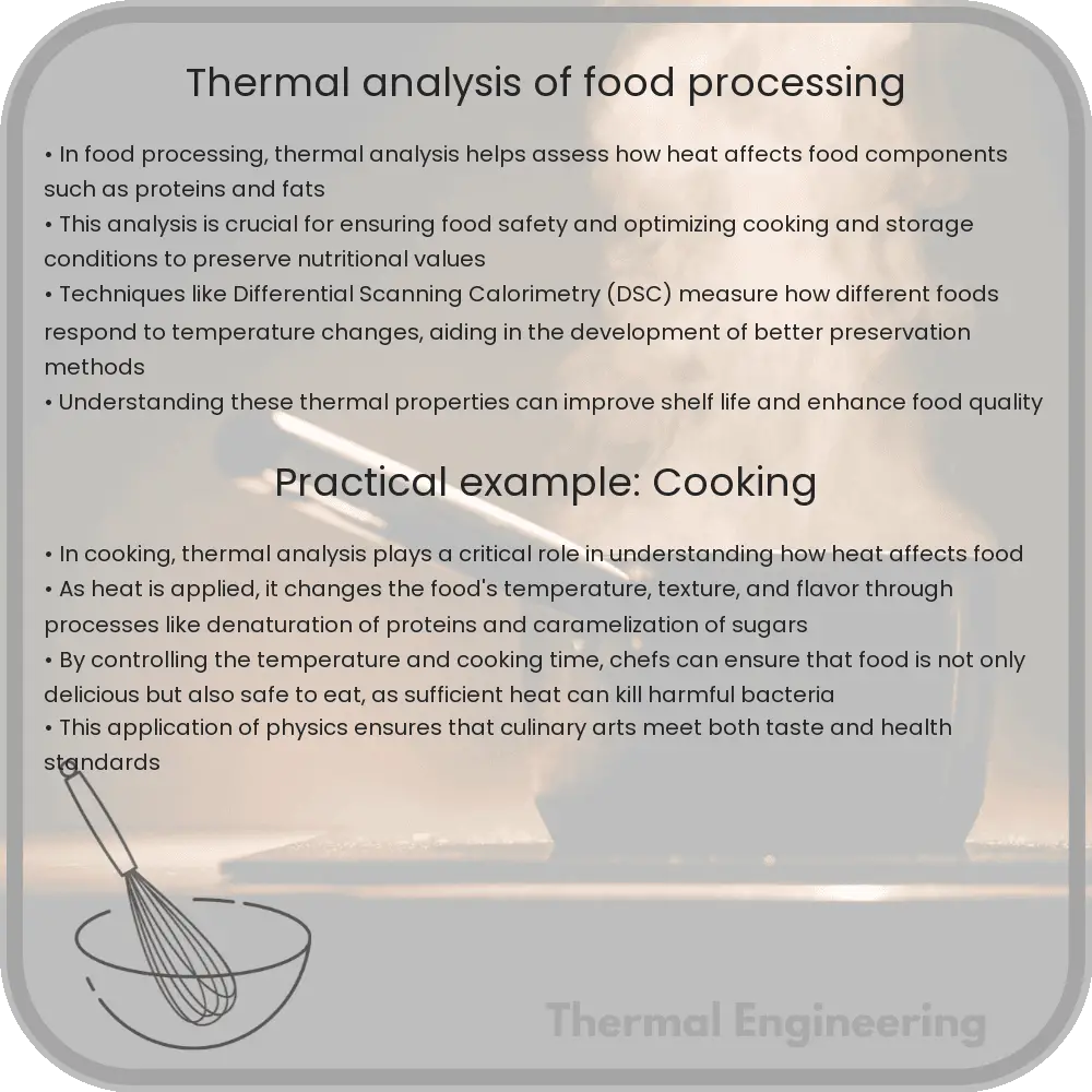
Thermal analysis of food processing

Thermal analysis in food processing examines how heat affects food’s safety, quality, and shelf life by studying physical and chemical property changes at varying temperatures.

Thermal analysis of food processing

Understanding Thermal Analysis in Food Processing

Thermal analysis in food processing is a critical aspect of engineering that focuses on understanding how heat treatment affects the safety, quality, and shelf life of food products. This type of analysis employs various techniques to measure changes in physical and chemical properties of food substances as they are subjected to different temperatures. In this article, we’ll explore the principles of thermal analysis, methods used, and its importance in maintaining food safety and quality.

Basic Principles of Thermal Analysis

At its core, thermal analysis in food processing investigates how heat transfers within food products and how this affects various attributes such as texture, color, nutritional content, and microbial load. The key principle underlying thermal analysis is the heat transfer equation, which can be expressed in its simplest form as:

q = m * c * ΔT

Where:

  • q represents the heat added or removed (in joules or calories),
  • m is the mass of the food item (in grams or kilograms),
  • c denotes the specific heat capacity of the food (J/g°C), and
  • ΔT is the change in temperature (°C).

Understanding this equation helps engineers design effective food processing systems that can control the amount of heat delivered or removed during processes such as cooking, freezing, or drying.

Methods of Thermal Analysis

  1. Differential Scanning Calorimetry (DSC): DSC measures the amount of heat required to increase the temperature of a food sample as compared to a reference. This method is particularly useful for detecting phase changes like melting or crystallization.
  2. Thermogravimetric Analysis (TGA): TGA measures changes in the mass of a food sample as it is heated or cooled. This can provide insights into moisture loss, decomposition, or oxidative stability.
  3. Thermal Conductivity: This method determines how well heat is transmitted through a food product, which affects cooling and heating rates during processing.

Importance of Thermal Analysis in Food Safety and Quality

Thermal analysis is integral to ensuring that food processing methods achieve the necessary microbial inactivation while maintaining nutrient integrity and sensory qualities. For instance, the precise calculation of heating times and temperatures can prevent the overcooking of foods, preserving vitamins and minerals that are sensitive to heat.

Moreover, thermal analysis aids in developing sterilization and pasteurization protocols. By determining the specific heat treatment required to destroy pathogens while minimizing quality degradation, food engineers can ensure the safety and efficacy of food preservation methods.

Applications of Thermal Analysis in Industry

In the food industry, thermal analysis is used in various applications, such as:

  • Developing new products: Understanding thermal properties helps in formulating recipes that can withstand processing temperatures while delivering on taste and texture.
  • Improving existing processes: By analyzing how heat affects different food components, engineers can optimize heating and cooling cycles to enhance efficiency and reduce energy costs.
  • Shelf life testing: Simulating how products respond to fluctuating storage temperatures helps predict shelf life based on how quickly they degrade.

In conclusion, thermal analysis plays a pivotal role in the engineering aspects of food processing. By deepening our understanding of heat effects on food, engineers are better equipped to design processes that enhance safety, efficiency, and product quality.

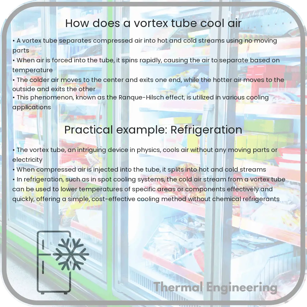
How does a vortex tube cool air

Explore how a vortex tube operates to separate compressed air into hot and cold streams using the principles of angular momentum and energy separation.

How does a vortex tube cool air

Understanding the Cooling Mechanism of a Vortex Tube

A vortex tube is a fascinating device that separates compressed air into hot and cold streams without the need for moving parts or electricity. Also known as a Ranque-Hilsch vortex tube, it presents an intriguing application of basic physics principles to create temperature separation based solely on the flow of air under pressure. Here’s how it works.

Principle of Operation

The vortex tube operates by injecting compressed air tangentially into a chamber, creating a high-speed spinning vortex. The air enters through a nozzle and is forced to rotate along the inner walls of the tube. This setup allows the tube to exploit the principles of angular momentum and energy separation effectively.

Components of a Vortex Tube

  • Intake valve: Where compressed air is introduced into the tube.
  • Swirl chamber: The section where the incoming air is accelerated and initiates a vortex.
  • Hot tube: The longer outer shell of the vortex where the outer layers of the air spiral down and are expelled as hot air.
  • Cold tube: The inner tube through which the center core of the air vortex flows, expelling colder air.

Thermal Separation Process

As the vortex of air spirals down the tube towards the hot end, two key processes occur:

  1. Conservation of Angular Momentum: As the radius of the spiral increases, the rotational velocity of the air decreases, according to the conservation of angular momentum (L = r * v, where L is angular momentum, r is radius, and v is velocity).
  2. Energy Separation: Due to the centrifugal force in the rapidly spinning air, the heavier, high-energy outer layers of the air are forced outward against the tube’s walls, moving towards the hot end. Meanwhile, the lower-energy, colder air remains on the inside and moves towards the opposite end.

Applications and Uses

Vortex tubes are utilized in various cooling applications where conventional electricity or refrigerants are impractical. Common uses include:

  • Cooling of cutting tools during machining operations.
  • Cooling of electronic and electrical equipment in harsh environments.
  • Environmental cooling in hazardous areas where traditional air conditioning systems are not feasible.

Efficiency and Environmental Impact

While vortex tubes offer a unique method for air temperature separation without chemical refrigerants, their efficiency is generally lower than that of traditional refrigeration equipment. Advances in vortex tube design continue to improve their efficiency and potential applications, making them a notable option in specific industrial applications.

Vortex tubes highlight how fundamental physics principles can be ingeniously applied in engineering to solve practical problems in innovative ways. Harnessing the power of air and its inherent properties allows for creative solutions in environments where traditional methods may fall short.

How does an airfoil produce lift

Learn how an airfoil produces lift, exploring aerodynamics, Bernoulli’s principle, airflow, and angle of attack for effective aircraft flight.

How does an airfoil produce lift

How Does an Airfoil Produce Lift?

The generation of lift by an airfoil is a fundamental concept in aerodynamics and is crucial for the flight of aircraft. An airfoil, commonly known as a wing, uses its shape and motion through air to lift the aircraft off the ground. Understanding how an airfoil produces lift involves a blend of physics principles, particularly those related to fluid dynamics and the Bernoulli’s Principle.

The Shape of an Airfoil

An airfoil is typically characterized by its curved upper surface and flatter lower surface. This design is intentional and critical for its function. When an airfoil moves through air, the air is split and forced to move over and under the wing.

The Path of Airflow and Lift Creation

The key to generating lift lies in the behavior of the airflow around the airfoil and the resulting pressure differences:

  • Longer Path Over the Top: Air traveling over the top of the wing follows a longer path than the air going underneath. This is primarily due to the curvature and thickness of the wing.
  • Increased Air Speed: According to Bernoulli’s principle, the increase in the velocity of the airflow over the top surface of the wing leads to a decrease in pressure.
  • Pressure Difference: The faster-moving air over the top of the airfoil creates a lower pressure area in comparison to the higher pressure on the underside of the wing. This difference in pressure results in an upward lifting force.

Angle of Attack and Lift

The angle of attack (AOA) is another critical factor in lift production. It is defined as the angle between the chord line of the wing and the oncoming air.

  • Optimal Angle: At the optimal angle of attack, lift is maximized and drag is minimized. This angle allows for the most effective deflection of airflow downwards, which according to Newton’s third law (action and reaction), results in an upward lift.
  • Stalling: If the angle of attack becomes too large, the smooth flow of air around the airfoil can separate from the upper surface, causing a sudden reduction in lift and an increase in drag, leading to a stall.

Mathematical Representation of Lift

The lift (L) generated by an airfoil can be calculated using the Lift Equation:

L = 0.5 * ρ * V2 * A * CL

  • ρ (rho): Air density
  • V: Velocity of the airflow
  • A: Wing area
  • CL: Lift coefficient, which is a measure of the ability of the wing to generate lift at given AOA and airspeed

Each of these components influences the amount of lift produced by an airfoil. For instance, increasing the airspeed or the angle of attack (up to a certain point before stall) typically increases the lift coefficient, thereby increasing the total lift force.

Conclusion

The production of lift by an airfoil is a fascinating blend of physics principles applied ingeniously in aircraft design. By understanding the interaction of airspeed, wing shape, angle of attack, and airflow behavior, engineers can optimize wings to achieve efficient, safe, and effective flight outcomes. Such principles not only apply to airplanes but also to various technologies such as wind turbines and race cars, showcasing the versatile implications of aerodynamic engineering.