Facebook Instagram Youtube Twitter

What is Definition of Fluid – Definition

By definition, a fluid material possesses no rigidity at all. Fluid is a substance that continually deforms (flows) under an applied shear stress. Thermal Engineering

Definition of Fluid

Definition of FluidIn physics, a fluid is a substance that continually deforms (flows) under an applied shear stress. The characteristic that distinguishes a fluid from a solid is its inability to resist deformation under an applied shear stress (a tangential force per unit area). Fluids are a subset of the phases of matter and include liquids, gases, plasmas and, to some extent, plastic solids.

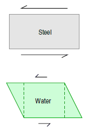
By definition, a solid material is rigid. For example, if one were to impose a shear stress on a solid block of steel, the block would not begin to change shape until an extreme amount of stress has been applied. To be more exact, when a shear stress is first applied to a rigid material it deforms slightly, but then springs back to its original shape when the stress is relieved.

Phase diagram of water
Phase diagram of water.
Source: wikipedia.org CC BY-SA

A plastic material, such as clay, also possess some degree of rigidity. However, the critical shear stress above which it yields is relatively small, and once this stress is exceeded the material deforms continuously and irreversibly, and does not recover
its original shape when the stress is relieved.

By definition, a fluid material possesses no rigidity at all. For example, if one were to impose a shear stress on a fluid element, the fluid element deforms, because it is unable to withstand any tendency of an applied shear stress to change its shape. Furthermore, the more stress that is applied, the more the fluid element will deform. This provides us with a characterizing feature of liquids (and gases—fluids, in general) that distinguishes them from other forms of matter, and we can thus give a formal definition.

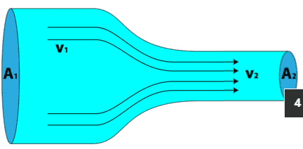
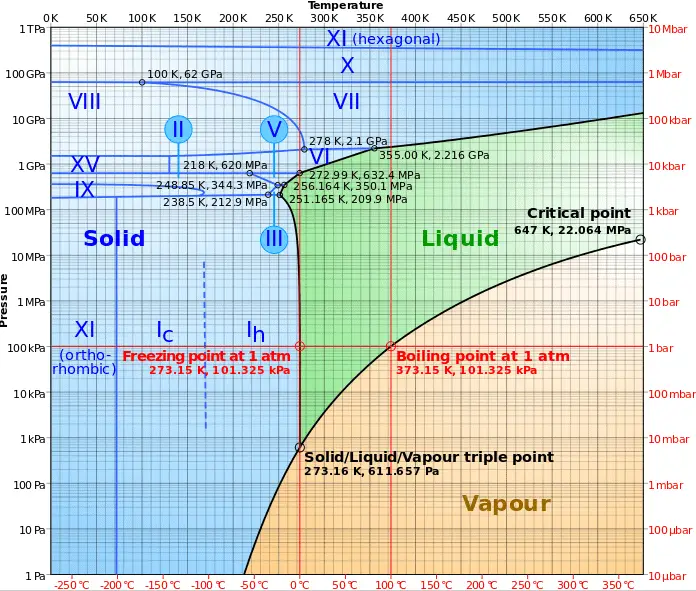
There are two types of fluid: liquids and gases. The most important difference between these two types of fluid is in their relative compressibility. Gases can be compressed much more easily than liquids. Consequently, any motion that involves significant pressure variations is generally accompanied by much larger changes in mass density in the case of a gas than in the case of a liquid.

 
Chart: Absolute pressure as a function of temperature of water
Water: Absolute pressure as a function of temperature
Chart: Density as a function of temperature of water
Chart - density - water - temperature
Density as a function of temperature of water
Chart: Dynamic viscosity as a function of temperature of water
Dynamic viscosity as a function of temperature of water
Chart: Dynamic viscosity as a function of temperature of water
Source: wikipedia.org CC BY-SA

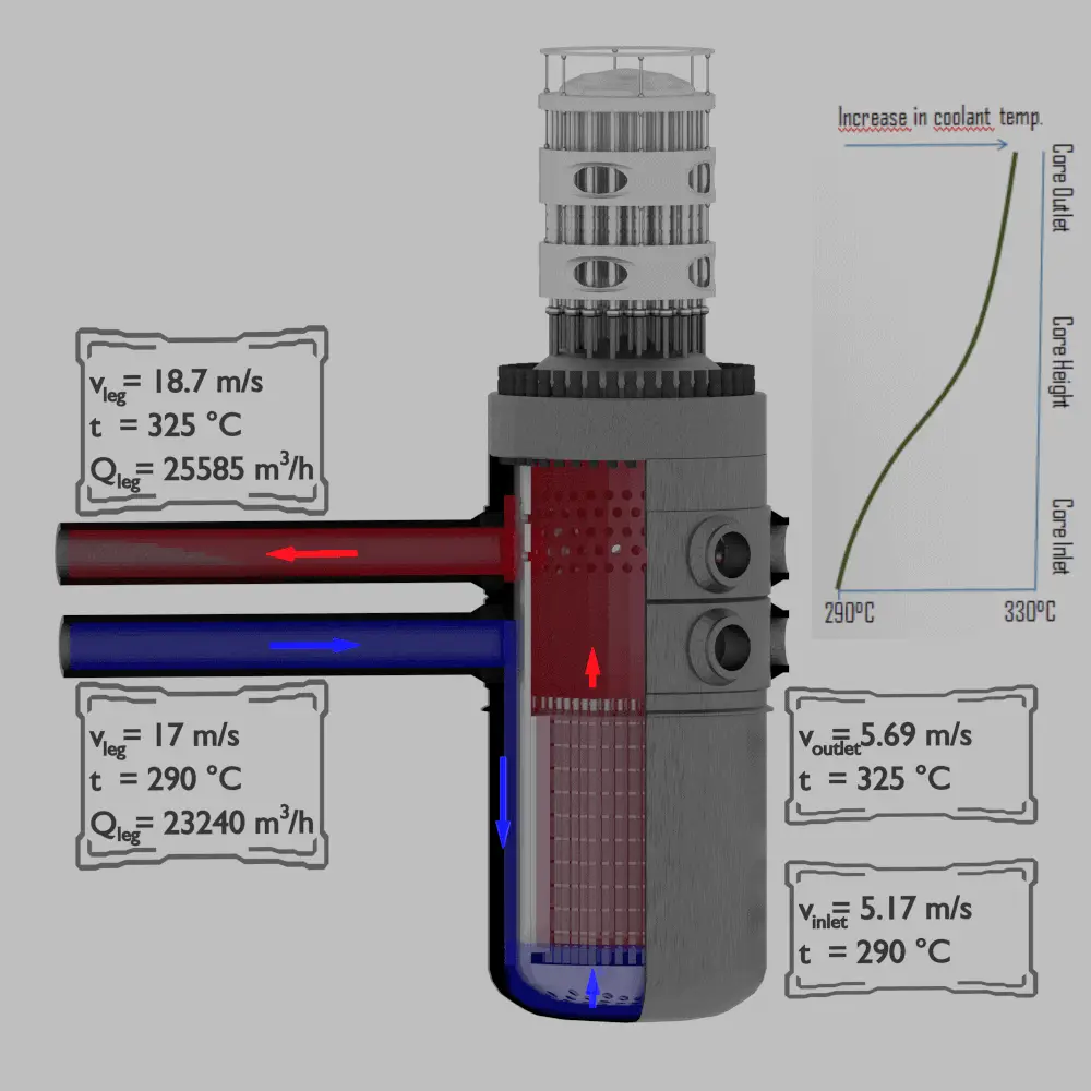
Water as a reactor coolant

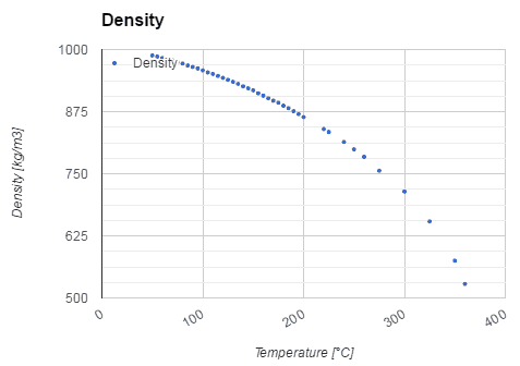
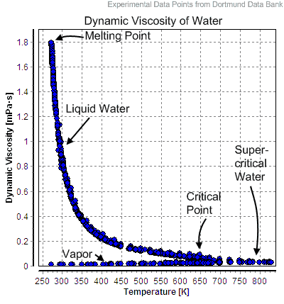
Water and steam are a common fluid used for heat exchange in the primary circuit (from surface of fuel rods to the coolant flow) and in the secondary circuit. It used due to its availability and high heat capacity, both for cooling and heating. It is especially effective to transport heat through vaporization and condensation of water because of its very large latent heat of vaporization.

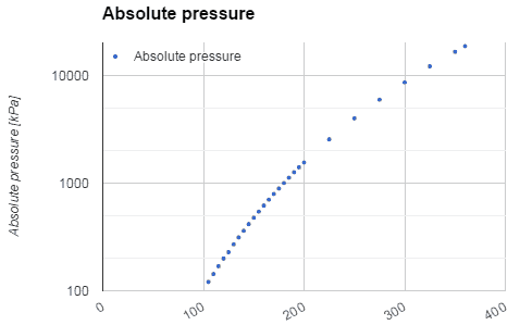
A disadvantage is that water moderated reactors have to use high pressure primary circuit in order to keep water in liquid state and in order to achieve sufficient thermodynamic efficiency. Water and steam also reacts with metals commonly found in industries such as steel and copper that are oxidized faster by untreated water and steam. In almost all thermal power stations (coal, gas, nuclear), water is used as the working fluid (used in a closed loop between boiler, steam turbine and condenser), and the coolant (used to exchange the waste heat to a water body or carry it away by evaporation in a cooling tower).

Water as a moderator

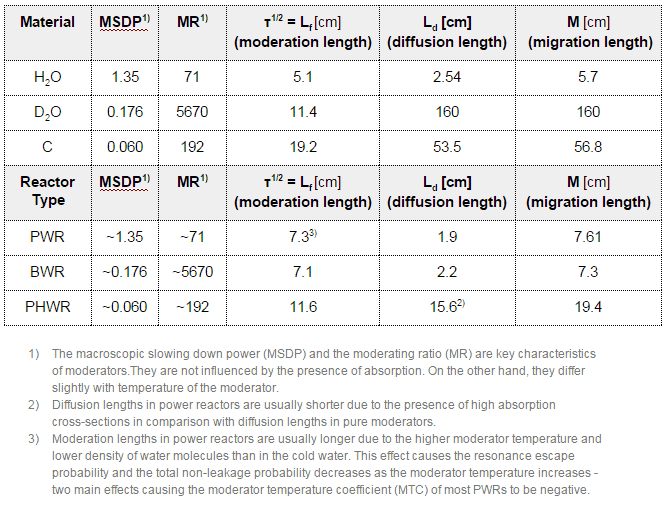
The neutron moderator, which is of importance in thermal reactors, is used to moderate, that is to slow down neutrons from fission to thermal energies. Nuclei with low mass numbers are most effective for this purpose, so the moderator is always a low-mass-number material. Commonly used moderators include regular (light) water (roughly 75% of the world’s reactors), solid graphite (20% of reactors) and heavy water (5% of reactors).

In most nuclear reactors, water is both a coolant and a moderator. The moderation occurs especially on hydrogen nuclei. In case of the hydrogen (A = 1) as the target nucleus, the incident neutron can be completely stopped – it has the highest average logarithmic energy decrement of all nuclei. On the other hand hydrogen nuclei have relatively higher absorption cross section, therefore water is not the best moderator according to the moderating ratio.

Neutron Moderators - Parameters

Water as a neutron shielding

Shielding of Neutron Radiation
Water as a neutron shield

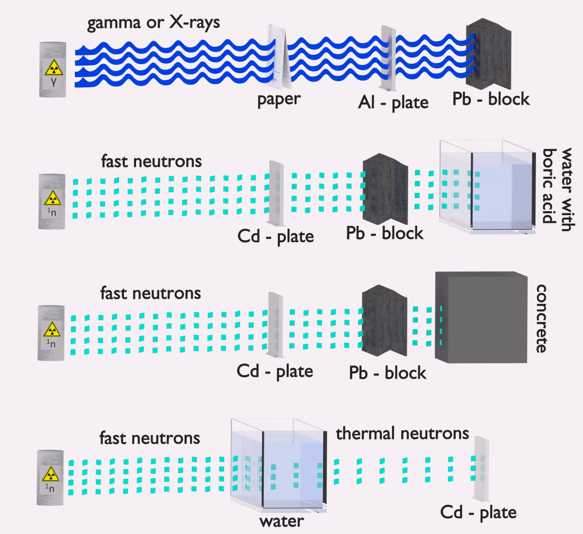
Water due to the high hydrogen content and the availability is efective and common neutron shielding. However, due to the low atomic number of hydrogen and oxygen, water is not acceptable shield against the gamma rays. On the other hand in some cases this disadvantage (low density) can be compensated by high thickness of the water shield.  In case of neutrons, water perfectly moderates neutrons, but with absorption of neutrons by hydrogen nucleus secondary gamma rays with the high energy are produced. These gamma rays highly penetrates matter and therefore it can increase requirements on the thickness of the water shield. Adding a boric acid can help with this problem (neutron absorbtion on boron nuclei without strong gamma emission), but results in another problems with corrosion of construction materials.

See also: Shielding of Neutrons

 
References:
Reactor Physics and Thermal Hydraulics:
  1. J. R. Lamarsh, Introduction to Nuclear Reactor Theory, 2nd ed., Addison-Wesley, Reading, MA (1983).
  2. J. R. Lamarsh, A. J. Baratta, Introduction to Nuclear Engineering, 3d ed., Prentice-Hall, 2001, ISBN: 0-201-82498-1.
  3. W. M. Stacey, Nuclear Reactor Physics, John Wiley & Sons, 2001, ISBN: 0- 471-39127-1.
  4. Glasstone, Sesonske. Nuclear Reactor Engineering: Reactor Systems Engineering, Springer; 4th edition, 1994, ISBN: 978-0412985317
  5. Todreas Neil E., Kazimi Mujid S. Nuclear Systems Volume I: Thermal Hydraulic Fundamentals, Second Edition. CRC Press; 2 edition, 2012, ISBN: 978-0415802871
  6. Zohuri B., McDaniel P. Thermodynamics in Nuclear Power Plant Systems. Springer; 2015, ISBN: 978-3-319-13419-2
  7. Moran Michal J., Shapiro Howard N. Fundamentals of Engineering Thermodynamics, Fifth Edition, John Wiley & Sons, 2006, ISBN: 978-0-470-03037-0
  8. Kleinstreuer C. Modern Fluid Dynamics. Springer, 2010, ISBN 978-1-4020-8670-0.
  9. U.S. Department of Energy, THERMODYNAMICS, HEAT TRANSFER, AND FLUID FLOW. DOE Fundamentals Handbook, Volume 1, 2 and 3. June 1992.

See also:

Fluid Dynamics

We hope, this article, Definition of Fluid, helps you. If so, give us a like in the sidebar. Main purpose of this website is to help the public to learn some interesting and important information about thermal engineering.

What is Continuity Equation – Definition

The continuity equation is simply a mathematical expression of the principle of conservation of mass. A general continuity equation can also be written in a differential form. Thermal Engineering

Conservation of Mass

The mass can neither be created nor destroyed.
Continuity Equation - Definition
Continuity Equation – Definition

This principle is generally known as the conservation of matter principle and states that the mass of an object or collection of objects never changes over time, no matter how the constituent parts rearrange themselves. This principle can be use in the analysis of flowing fluids. Conservation of mass in fluid dynamics states that all mass flow rates into a control volume are equal to all mass flow rates out of the control volume plus the rate of change of mass within the control volume. This principle is expressed mathematically by following equation:

in = ṁout +∆m∆t

Mass entering per unit time = Mass leaving per unit time + Increase of mass in the control volume per unit time

Continuity Equation - Flow Rates through Reactor
Example of flow rates in a reactor. It is an illustrative example, data do not represent any reactor design.

This equation describes nonsteady-state flow. Nonsteady-state flow refers to the condition where the fluid properties at any single point in the system may change over time. Steady-state flow refers to the condition where the fluid properties (temperature, pressure, and velocity) at any single point in the system do not change over time. But one of the most significant properties that is constant in a steady-state flow system is the system mass flow rate. This means that there is no accumulation of mass within any component in the system.

Continuity Equation

The continuity equation is simply a mathematical expression of the principle of conservation of mass. For a control volume that has a single inlet and a single outlet, the principle of conservation of mass states that, for steady-state flow, the mass flow rate into the volume must equal the mass flow rate out.

in = ṁout 

Mass entering per unit time = Mass leaving per unit time

This equation is called the continuity equation for steady one-dimensional flow. For a steady flow through a control volume with many inlets and outlets, the net mass flow must be zero, where inflows are negative and outflows are positive.

This principle can be applied to a streamtube such as that shown above. No fluid flows across the boundary made by the streamlines so mass only enters and leaves through the two ends of this streamtube section.

When a fluid is in motion, it must move in such a way that mass is conserved. To see how mass conservation places restrictions on the velocity field, consider the steady flow of fluid through a duct (that is, the inlet and outlet flows do not vary with time).

Differential Form of Continuity Equation

A general continuity equation can also be written in a differential form:

∂⍴∂t + ∇ . (⍴ ͞v) = σ

where

  • ∇ . is divergence,
  • ρ is the density of quantity q,
  • ⍴ ͞v is the flux of quantity q,
  • σ is the generation of q per unit volume per unit time. Terms that generate (σ > 0) or remove (σ < 0) q are referred to as a “sources” and “sinks” respectively. If q is a conserved quantity (such as energy), σ is equal to 0.

Continuity Equation – Multiple Inlets and Outlets

For a control volume with multiple inlets and outlets, the principle of conservation of mass requires that the sum of the mass flow rates into the control volume equal the sum of the mass flow rates out of the control volume. The continuity equation for this more general situation is expressed by following equation:

∑ṁin = ∑ṁout 

Sum of mass flow rates entering per unit time = Sum of mass flow rates leaving per unit time

Continuity Equation – Examples

Flow rate through a reactor core

In this example, we will calculate the flow rate through a reactor core from continuity equation. It is an illustrative example, following data do not represent any reactor design.

in = ṁout 

(ρAv)in = (ρAv)out 

____________________________

Chart - density - water - temperature
Density as a function of temperature of water

Pressurized water reactors are cooled and moderated by high-pressure liquid water (e.g. 16MPa). At this pressure water boils at approximately 350°C (662°F).  Inlet temperature of the water is about 290°C (⍴ ~ 720 kg/m3). The water (coolant) is heated in the reactor core to approximately 325°C (⍴ ~ 654 kg/m3) as the water flows through the core.
The primary circuit of typical PWR is divided into 4 independent loops (piping diameter ~ 700mm), each loop comprises a steam generator and one main coolant pump. Inside the reactor pressure vessel (RPV), the coolant first flows down outside the reactor core (through the downcomer). From the bottom of the pressure vessel, the flow is reversed up through the core, where the coolant temperature increases as it passes through the fuel rods and the assemblies formed by them.

Calculate:

  • the primary piping volumetric flow rate (m3/s),
  • the primary piping flow velocity (m/s),
  • the core inlet flow velocity (m/s),
  • the core outlet flow velocity (m/s)

when

  • the mass flow rate in the hot leg of primary piping is equal to 4648 kg/s,
  • Reactor core flow cross-section is equal to 5m2,
  • Primary piping flow cross-section (single loop) is equal to 0.38 m2

Results:

Continuity Equation - Flow Rates through Reactor
Example of flow rates in a reactor. It is an illustrative example, data do not represent any reactor design.

Cold leg volumetric flow rate:

Qcold = ṁ / ⍴ = 4648 / 720 = 6.46 m3/s = 23240 m3/hod

Cold leg flow velocity:

A1 = π.d2 / 4

vcold = Qcold / A1 = 6.46 / (3.14 x 0.72 / 4) = 6.46 / 0.38 = 17 m/s

Hot leg volumetric flow rate:

Qhot = ṁ / ⍴ = 4648 / 654 = 7.11 m3/s = 25585 m3/hod

Hot leg flow velocity:

A = π.d2 / 4

vhot = Qhot / A1 = 7.11 / (3.14 x 0.72 / 4) = 7.11 / 0.38 = 18,7 m/s

or according to the continuity equation:

1 . A1 . v1 = ⍴2 . A2 . v2

vhot =  vcold . ⍴cold / ⍴hot = 17 x 720 / 654 = 18.7 m/s

Core inlet flow velocity:

Acore = 5m2

Apiping = 4 x A1 = 4 x 0.38 = 1.52 m2

inlet = ⍴cold

according to the continuity equation:

inlet . Acore . vinlet = ⍴cold . Apiping . vcold

vinlet =  vcold . Apiping / Acore = 17 x 1.52 / 5 = 5.17 m/s

Core outlet flow velocity:

inlet = ⍴cold

outlet = ⍴hot

according to the continuity equation:

outlet . Acore . voutlet = ⍴inlet . Acore . vinlet
voutlet =  vinlet . ⍴inlet / ⍴outlet = 5.17 x 720 / 654 = 5.69 m/s

 
References:
Reactor Physics and Thermal Hydraulics:
  1. J. R. Lamarsh, Introduction to Nuclear Reactor Theory, 2nd ed., Addison-Wesley, Reading, MA (1983).
  2. J. R. Lamarsh, A. J. Baratta, Introduction to Nuclear Engineering, 3d ed., Prentice-Hall, 2001, ISBN: 0-201-82498-1.
  3. W. M. Stacey, Nuclear Reactor Physics, John Wiley & Sons, 2001, ISBN: 0- 471-39127-1.
  4. Glasstone, Sesonske. Nuclear Reactor Engineering: Reactor Systems Engineering, Springer; 4th edition, 1994, ISBN: 978-0412985317
  5. Todreas Neil E., Kazimi Mujid S. Nuclear Systems Volume I: Thermal Hydraulic Fundamentals, Second Edition. CRC Press; 2 edition, 2012, ISBN: 978-0415802871
  6. Zohuri B., McDaniel P. Thermodynamics in Nuclear Power Plant Systems. Springer; 2015, ISBN: 978-3-319-13419-2
  7. Moran Michal J., Shapiro Howard N. Fundamentals of Engineering Thermodynamics, Fifth Edition, John Wiley & Sons, 2006, ISBN: 978-0-470-03037-0
  8. Kleinstreuer C. Modern Fluid Dynamics. Springer, 2010, ISBN 978-1-4020-8670-0.
  9. U.S. Department of Energy, THERMODYNAMICS, HEAT TRANSFER, AND FLUID FLOW. DOE Fundamentals Handbook, Volume 1, 2 and 3. June 1992.

See also:

Fluid Dynamics

We hope, this article, Continuity Equation, helps you. If so, give us a like in the sidebar. Main purpose of this website is to help the public to learn some interesting and important information about thermal engineering.

What is Bernoulli’s Equation – Bernoulli’s Principle – Definition

Bernoulli’s Equation – Bernoulli’s Principle. It can be considered to be a statement of the conservation of energy principle appropriate for flowing fluids.

Conservation of Energy

Energy can neither be created nor destroyed.
This principle is generally known as the conservation of energy principle and states that the total energy of an isolated system remains constant — it is said to be conserved over time. This is equivalent to the First Law of Thermodynamics, which is used to develop the general energy equation in thermodynamics. This principle can be use in the analysis of flowing fluids and this principle is expressed mathematically by following equation:

Conservation of energy - fluidswhere h is enthalpy, k is the thermal conductivity of the fluid, T is temperature, and Φ is the viscous dissipation function.

 
Derivation of Bernoulli's Equation
Derivation of Bernoulli EquationThe Bernoulli’s equation for incompressible fluids can be derived from the Euler’s equations of motion under rather severe restrictions.
  • The velocity must be derivable from a velocity potential.
  • External forces must be conservative. That is, derivable from a potential.
  • The density must either be constant, or a function of the pressure alone.
  • Thermal effects, such as natural convection, are ignored.

In fluid dynamics, the Euler equations are a set of quasilinear hyperbolic equations governing adiabatic and inviscid flow. Euler equations can be obtained by linearization of these Navier–Stokes equations.

Bernoulli’s Equation

Bernoulli Equation; PrincipleThe Bernoulli’s equation can be considered to be a statement of the conservation of energy principle appropriate for flowing fluids. It is one of the most important/useful equations in fluid mechanics. It puts into a relation pressure and velocity in an inviscid incompressible flow. Bernoulli’s equation has some restrictions in its applicability, they summarized in following points:

  • steady flow system,
  • density is constant (which also means the fluid is incompressible),
  • no work is done on or by the fluid,
  • no heat is transferred to or from the fluid,
  • no change occurs in the internal energy,
  • the equation relates the states at two points along a single streamline (not conditions on two different streamlines)

Under these conditions, the general energy equation is simplified to:

Bernoulli Theorem - Equation
This equation is the most famous equation in fluid dynamics. The Bernoulli’s equation describes the qualitative behavior flowing fluid that is usually labeled with the term Bernoulli’s effect. This effect causes the lowering of fluid pressure in regions where the flow velocity is increased. This lowering of pressure in a constriction of a flow path may seem counterintuitive, but seems less so when you consider pressure to be energy density. In the high velocity flow through the constriction, kinetic energy must increase at the expense of pressure energy. The dimensions of terms in the equation are kinetic energy per unit volume.

 
Static Pressure
In general, pressure is a measure of the force exerted per unit area on the boundaries of a substance. In fluid dynamics, many authors use the term static pressure in preference to just pressure to avoid ambiguity. The term static pressure is identical to the term pressure, and can be identified for every point in a fluid flow field.

Static pressure is one of the terms of Bernoulli’s equation:

Bernoulli Theorem - Equation

The Bernoulli’s effect causes the lowering of fluid pressure (static pressure – p) in regions where the flow velocity is increased. This lowering of pressure in a constriction of a flow path may seem counterintuitive, but seems less so when you consider pressure to be energy density. In the high velocity flow through the constriction, kinetic energy (dynamic pressure – ½.ρ.v2) must increase at the expense of pressure energy (static pressure – p).

The simplified form of Bernoulli’s equation can be summarized in the following memorable word equation:

static pressure + dynamic pressure = total pressure (stagnation pressure)

Total and dynamic pressure are not pressures in the usual sense – they cannot be measured using an aneroid, Bourdon tube or mercury column.

Dynamic Pressure
In general, pressure is a measure of the force exerted per unit area on the boundaries of a substance. The term dynamic pressure (sometimes called velocity pressure)  is associated with fluid flow and with the Bernoulli’s effect, which is described by the Bernoulli’s equation:

Bernoulli Theorem - Equation

This effect causes the lowering of fluid pressure (static pressure) in regions where the flow velocity is increased. This lowering of pressure in a constriction of a flow path may seem counterintuitive, but seems less so when you consider pressure to be energy density. In the high velocity flow through the constriction, kinetic energy (dynamic pressure – ½.ρ.v2) must increase at the expense of pressure energy (static pressure – p).

As can be seen, dynamic pressure is dynamic pressure is one of the terms of Bernoulli’s equation. In incompressible fluid dynamics, dynamic pressure is the quantity defined by:

dynamic pressure - formula

The simplified form of Bernoulli’s equation can be summarized in the following memorable word equation:

static pressure + dynamic pressure = total pressure (stagnation pressure)

Total and dynamic pressure are not pressures in the usual sense – they cannot be measured using an aneroid, Bourdon tube or mercury column.

To avoid potential ambiguity when referring to pressure in fluid dynamics, many authors use the term static pressure to distinguish it from total pressure and dynamic pressure. The term static pressure is identical to the term pressure, and can be identified for every point in a fluid flow field. Dynamic pressure is the difference between stagnation pressure and static pressure.

Stagnation Pressure (Total Pressure)
In general, pressure is a measure of the force exerted per unit area on the boundaries of a substance. In fluid dynamics and aerodynamics, stagnation pressure (or pitot pressure or total pressure) is the static pressure at a stagnation point in a fluid flow. At a stagnation point the fluid velocity is zero and all kinetic energy has been converted into pressure energy (isentropically). This effect is widely used in aerodynamics (velocity measurement or ram-air intake).

Stagnation pressure is equal to the sum of the free-stream dynamic pressure and free-stream static pressure.

stagnation pressure - total pressure

Static pressure and dynamic pressure are terms of Bernoulli’s equation:

Bernoulli Theorem - Equation

The Bernoulli’s effect causes the lowering of fluid pressure (static pressure – p) in regions where the flow velocity is increased. This lowering of pressure in a constriction of a flow path may seem counterintuitive, but seems less so when you consider pressure to be energy density. In the high velocity flow through the constriction, kinetic energy (dynamic pressure – ½.ρ.v2) must increase at the expense of pressure energy (static pressure – p).

The simplified form of Bernoulli’s equation can be summarized in the following memorable word equation:

static pressure + dynamic pressure = total pressure (stagnation pressure)

Total and dynamic pressure are not pressures in the usual sense – they cannot be measured using an aneroid, Bourdon tube or mercury column.

Stagnation pressure is sometimes referred to as pitot pressure because it is measured using a pitot tube. A Pitot tube is a pressure measurement instrument used to measure fluid flow velocity. Velocity can be determined using the following formula:

pitot tube - formula - velocity

where:

  • u is flow velocity to be measured in m/s,
  • pis stagnation or total pressure in Pa,
  • pt is static pressure in Pa,
  • ρ is fluid density in kg/m3.
 
Hydraulic Head
In general, the hydraulic head, or total head, is a measure of the potential of fluid at the measurement point. It can be used to determine a hydraulic gradient between two or more points.
Bernoulli Theorem - Equation
Q-H characteristic diagram of centrifugal pump and of pipeline

In fluid dynamics, head is a concept that relates the energy in an incompressible fluid to the height of an equivalent static column of that fluid. The units for all the different forms of energy in the Bernoulli’s equation can be measured also in units of distance, and therefore these terms are sometimes referred to as “heads” (pressure head, velocity head, and elevation head). Head is also defined for pumps. This head is usually referred to as the static head and represents the maximum height (pressure) it can deliver. Therefore the characteristics of all pumps can be usually read from its Q-H curve (flow rate – height).

There are four types of potential (head):

  • Pressure potential – Pressure head: The pressure head represents the flow energy of a column of fluid whose weight is equivalent to the pressure of the fluid.Pressure Headρw: density of water assumed to be independent of pressure
  • Elevation potential – Elevation head: The elevation head represents the potential energy of a fluid due to its elevation above a reference level.Elevation Head
  • Kinetic potential – Kinetic head: The kinetic head represents the kinetic energy of the fluid. It is the height in feet that a flowing fluid would rise in a column if all of its kinetic energy were converted to potential energy.Kinetic Head

The sum of the elevation head, kinetic head, and pressure head of a fluid is called the total head. Thus, Bernoulli’s equation states that the total head of the fluid is constant.
Total Hydraulic Head
Consider a pipe containing an ideal fluid. If this pipe undergoes a gradual expansion in diameter, the continuity equation tells us that as the pipe diameter increases, the flow velocity must decrease in order to maintain the same mass flow rate. Since the outlet velocity is less than the inlet velocity, the kinetic head of the flow must decrease from the inlet to the outlet. If there is no change in elevation head (the pipe lies horizontal), the decrease in kinetic head must be compensated for by an increase in pressure head.

Example: Hydraulic Head

Hydraulic Head - Total Head Line
Piezometer levels when fluid is flowing. In this figure that the levels have reduced by an amount equal to the velocity head.
Hydraulic Head - Velocity Head
Piezometer levels and velocity heads with fluid flowing in varying diameter pipes. The velocity head at each point is now different. This is because the velocity is different at each point.
Hydraulic Head - Hydraulic Grade Line
Hydraulic Grade line and Total head lines for a constant diameter pipe with friction. In a real pipe line there are energy losses due to friction – these must be taken into account as they can be very significant.
Example: Frictional Head Loss
Water at 20°C is pumped through a smooth 12-cm-diameter pipe 10 km long, at a flow rate of 75 m3/h. The inlet is fed by a pump at an absolute pressure of 2.4 MPa.
The exit is at standard atmospheric pressure (101 kPa) and is 200 m higher.

Calculate the frictional head loss Hf, and compare it to the velocity head of the flow v2/(2g).

Solution:

Since the pipe diameter is constant, the average velocity and velocity head is the same everywhere:

vout = Q/A = 75 [m3/h] * 3600 [s/h] / 0.0113 [m2] = 1.84 m/s

Velocity head:

Velocity head = vout2/(2g) = 1.842 / 2*9.81 = 0.173 m

In order to find the frictional head loss, we have to use extended Bernoulli’s equation:

Extended Bernoulli Equation

Head loss:

2 400 000 [Pa] / 1000 [kg/m3] * 9.81 [m/s2]  + 0.173 [m] + 0 [m] = 101 000 [Pa] / 1000 [kg/m3] * 9.81 [m/s2] + 0.173 [m]+ 200 [m] + Hf

H = 244.6 – 10.3 – 200 = 34.3 m

Extended Bernoulli’s Equation

There are two main assumptions, that were applied on the derivation of the simplified Bernoulli’s equation.

  • The first restriction on Bernoulli’s equation is that no work is allowed to be done on or by the fluid. This is a significant limitation, because most hydraulic systems (especially in nuclear engineering) include pumps. This restriction prevents two points in a fluid stream from being analyzed if a pump exists between the two points.
  • The second restriction on simplified Bernoulli’s equation is that no fluid friction is allowed in solving hydraulic problems. In reality, friction plays crucial role. The total head possessed by the fluid cannot be transferred completely and lossless from one point to another. In reality, one purpose of pumps incorporated in a hydraulic system is to overcome the losses in pressure due to friction.
Q-H characteristic diagram of centrifugal pump and of pipeline

Due to these restrictions most of practical applications of the simplified Bernoulli’s equation to real hydraulic systems are very limited. In order to deal with both head losses and pump work, the simplified Bernoulli’s equation must be modified.

The Bernoulli equation can be modified to take into account gains and losses of head. The resulting equation, referred to as the extended Bernoulli’s equation, is very useful in solving most fluid flow problems. The following equation is one form of the extended Bernoulli’s equation.

Extended Bernoulli Equation

where:
h = height above reference level (m)
v = average velocity of fluid (m/s)
p = pressure of fluid (Pa)
Hpump = head added by pump (m)
Hfriction = head loss due to fluid friction (m)
g = acceleration due to gravity (m/s2)

The head loss (or the pressure loss) due to fluid friction (Hfriction) represents the energy used in overcoming friction caused by the walls of the pipe. The head loss that occurs in pipes is dependent on the flow velocity, pipe diameter and length, and a friction factor based on the roughness of the pipe and the Reynolds number of the flow. A piping system containing many pipe fittings and joints, tube convergence, divergence, turns, surface roughness and other physical properties will also increase the head loss of a hydraulic system.

Although the head loss represents a loss of energy, it does does not represent a loss of total energy of the fluid. The total energy of the fluid conserves as a consequence of the law of conservation of energy. In reality, the head loss due to friction results in an equivalent increase in the internal energy (increase in temperature) of the fluid.

Most methods for evaluating head loss due to friction are based almost exclusively on experimental evidence. This will be discussed in following sections.

Examples – Bernoulli’s Principle

Bernoulli’s Effect – Relation between Pressure and Velocity

It is an illustrative example, following data do not correspond to any reactor design.

Continuity Equation - Flow Rates through Reactor
Example of flow rates in a reactor. It is an illustrative example, data do not represent any reactor design.

When the Bernoulli’s equation is combined with the continuity equation the two can be used to find velocities and pressures at points in the flow connected by a streamline.

The continuity equation is simply a mathematical expression of the principle of conservation of mass. For a control volume that has a single inlet and a single outlet, the principle of conservation of mass states that, for steady-state flow, the mass flow rate into the volume must equal the mass flow rate out.

Example:

Determine pressure and velocity within a cold leg of primary piping and determine pressure and velocity at a bottom of a reactor core, which is about 5 meters below the cold leg of primary piping.

Let assume:

  • Fluid of constant density ⍴ ~ 720 kg/m3 (at 290°C) is flowing steadily through the cold leg and through the core bottom.
  • Primary piping flow cross-section (single loop) is equal to 0.385 m2 (piping diameter ~ 700mm)
  • Flow velocity in the cold leg is equal to 17 m/s.
  • Reactor core flow cross-section is equal to 5m2.
  • The gauge pressure inside the cold leg is equal to 16 MPa.

As a result of the Continuity principle the velocity at the bottom of the core is:

vinlet =  vcold . Apiping / Acore = 17 x 1.52 / 5 = 5.17 m/s

As a result of the Bernoulli’s principle the pressure at the bottom of the core (core inlet) is:

Bernoulli Principle - Example

Bernoulli’s Principle – Lift Force

Lift Force - Newtons Law
Newton’s third law states that the lift is caused by a flow deflection.

In general, the lift is an upward-acting force on an aircraft wing or airfoil. There are several ways to explain how an airfoil generates lift. Some theories are more complicated or more mathematically rigorous than others. Some theories have been shown to be incorrect. There are theories based on the Bernoulli’s principle and there are theories based on directly on the Newton’s third law.

The explanation based on the Newton’s third law states that the lift is caused by a flow deflection of the airstream behind the airfoil. The airfoil generates lift by exerting a downward force on the air as it flows past. According to Newton’s third law, the air must exert an upward force on the airfoil. This is very simple explanation.

Lift Force - Bernoulli Principle
According to the Bernoulli’s principle, faster moving air exerts less pressure, and therefore the air must exert an upward force on the airfoil (as a result of a pressure difference).

Bernoulli’s principle combined with the continuity equation can be also used to determine the lift force on an airfoil, if the behaviour of the fluid flow in the vicinity of the foil is known. In this explanation the shape of an airfoil is crucial. The shape of an airfoil causes air to flow faster on top than on bottom. According to Bernoulli’s principle, faster moving air exerts less pressure, and therefore the air must exert an upward force on the airfoil (as a result of a pressure difference).

 
Lift coefficient as a function of Angle of Attack
Lift Coefficient - Flaps
Source: www.zenithair.net
Bernoulli’s principle requires airfoil to be of an asymmetrical shape. Its surface area must be greater on the top than on the bottom. As the air flows over the airfoil, it is displaced more by the top surface than the bottom. According to the continuity principle, this displacement must lead to an increase in flow velocity (resulting in a decrease in pressure). The flow velocity is increased some by the bottom airfoil surface, but considerably less than the flow on the top surface. The lift force of an airfoil, characterized by the lift coefficient, can be changed during the flight by changes in shape of an airfoil. The lift coefficient can thus be even doubled with relatively simple devices (flaps and slats) if used on the full span of the wing.

The use of Bernoulli’s principle may not be correct. The Bernoulli’s principle assumes incompressibility of the air, but in reality the air is easily compressible. But there are more limitations of explanations based on Bernoulli’s principle. There are two main popular explanations of lift:

  • Explanation based on downward deflection of the flow – Newton’s third law
  • Explanation based on changes in flow speed and pressure – Continuity principle and Bernoulli’s principle

Both explanations correctly identifies some aspects of the lift forces but leaves other important aspects of the phenomenon unexplained. A more comprehensive explanation involves both changes in flow speed and downward deflection and requires looking at the flow in more detail.

See more: Doug McLean, Understanding Aerodynamics: Arguing from the Real Physics. John Wiley & Sons Ltd. 2013. ISBN:  978-1119967514

Bernoulli’s Effect – Spinning ball in an airflow

Bernoulli Principle - Spinning ballThe Bernoulli’s effect has another interesting interesting consequence. Suppose a ball is spinning as it travels through the air. As the ball spins, the surface friction of the ball with the surrounding air drags a thin layer (referred to as the boundary layer) of air with it. It can be seen from the picture the boundary layer is on one side traveling in the same direction as the air stream that is flowing around the ball (the upper arrow) and on the other side, the boundary layer is traveling in the opposite direction (the bottom arrow). On the side of the ball where the air stream and boundary layer are moving in the opposite direction (the bottom arrow) to each other friction between the two slows the air stream. On the opposite side these layers are moving in the same direction and the stream moves faster.

According to Bernoulli’s principle, faster moving air exerts less pressure, and therefore the air must exert an upward force on the ball. In fact, in this case the use of Bernoulli’s principle may not be correct. The Bernoulli’s principle assumes incompressibility of the air, but in reality the air is easily compressible. But there are more limitations of explanations based on Bernoulli’s principle.

The work of Robert G. Watts and Ricardo Ferrer (The lateral forces on a spinning sphere: Aerodynamics of a curveball) this effect can be explained by another model which gives important attention to the spinning boundary layer of air around the ball. On the side of the ball where the air stream and boundary layer are moving in the opposite direction (the bottom arrow), the boundary layer tends to separate prematurely. On the side of the ball where the air stream and boundary layer are moving in the same direction , the boundary layer carries further around the ball before it separates into turbulent flow. This gives a flow deflection of the airstream in one direction behind the ball. The rotating ball generates lift by exerting a downward force on the air as it flows past. According to Newton’s third law, the air must exert an upward force on the ball.

Torricelli’s law

Torricelli’s law
Source: wikipedia.org – CC BY-SA

Torricelli’s law, also known as Torricelli’s principle, or Torricelli’s theorem, statement in fluid dynamics that the speed, v, of fluid flowing out of an orifice under the force of gravity in a tank is proportional to the square root of the vertical distance, h, between the liquid surface and the centre of the orifice and to the square root of twice the acceleration caused by gravity (g = 9.81 N/kg near the surface of the earth).

In other words, the efflux velocity of the fluid from the orifice is the same as that it would have acquired by falling a height h under gravity. The law was discovered by and named after the Italian scientist Evangelista Torricelli, in 1643. It was later shown to be a particular case of Bernoulli’s principle.
Bernoulli Theorem - Equation

The Torricelli’s equation is derived for a specific condition. The orifice must be small and viscosity and other losses must be ignored. If a fluid is flowing through a very small orifice (for example at the bottom of a large tank) then the velocity of the fluid at the large end can be neglected in Bernoulli’s Equation. Moreover the speed of efflux is independent of the direction of flow. In that case the efflux speed of fluid flowing through the orifice given by following formula:

v = √2gh

 
References:
Reactor Physics and Thermal Hydraulics:
  1. J. R. Lamarsh, Introduction to Nuclear Reactor Theory, 2nd ed., Addison-Wesley, Reading, MA (1983).
  2. J. R. Lamarsh, A. J. Baratta, Introduction to Nuclear Engineering, 3d ed., Prentice-Hall, 2001, ISBN: 0-201-82498-1.
  3. W. M. Stacey, Nuclear Reactor Physics, John Wiley & Sons, 2001, ISBN: 0- 471-39127-1.
  4. Glasstone, Sesonske. Nuclear Reactor Engineering: Reactor Systems Engineering, Springer; 4th edition, 1994, ISBN: 978-0412985317
  5. Todreas Neil E., Kazimi Mujid S. Nuclear Systems Volume I: Thermal Hydraulic Fundamentals, Second Edition. CRC Press; 2 edition, 2012, ISBN: 978-0415802871
  6. Zohuri B., McDaniel P. Thermodynamics in Nuclear Power Plant Systems. Springer; 2015, ISBN: 978-3-319-13419-2
  7. Moran Michal J., Shapiro Howard N. Fundamentals of Engineering Thermodynamics, Fifth Edition, John Wiley & Sons, 2006, ISBN: 978-0-470-03037-0
  8. Kleinstreuer C. Modern Fluid Dynamics. Springer, 2010, ISBN 978-1-4020-8670-0.
  9. U.S. Department of Energy, THERMODYNAMICS, HEAT TRANSFER, AND FLUID FLOW. DOE Fundamentals Handbook, Volume 1, 2 and 3. June 1992.
  10. White Frank M., Fluid Mechanics, McGraw-Hill Education, 7th edition, February, 2010, ISBN: 978-0077422417

See also:

Fluid Dynamics

We hope, this article, Bernoulli’s Equation – Bernoulli’s Principle, helps you. If so, give us a like in the sidebar. Main purpose of this website is to help the public to learn some interesting and important information about thermal engineering.

What is Derivation of Bernoulli’s Equation – Definition

Derivation of Bernoulli’s Equation. The Bernoulli’s equation for incompressible fluids can be derived from the Euler’s equations under certain restrictions.

Derivation of Bernoulli’s Equation

Derivation of Bernoulli EquationThe Bernoulli’s equation for incompressible fluids can be derived from the Euler’s equations of motion under rather severe restrictions.

  • The velocity must be derivable from a velocity potential.
  • External forces must be conservative. That is, derivable from a potential.
  • The density must either be constant, or a function of the pressure alone.
  • Thermal effects, such as natural convection, are ignored.

In fluid dynamics, the Euler equations are a set of quasilinear hyperbolic equations governing adiabatic and inviscid flow. Euler equations can be obtained by linearization of these Navier–Stokes equations.

Bernoulli’s Equation

Bernoulli Equation; PrincipleThe Bernoulli’s equation can be considered to be a statement of the conservation of energy principle appropriate for flowing fluids. It is one of the most important/useful equations in fluid mechanics. It puts into a relation pressure and velocity in an inviscid incompressible flow. Bernoulli’s equation has some restrictions in its applicability, they summarized in following points:

  • steady flow system,
  • density is constant (which also means the fluid is incompressible),
  • no work is done on or by the fluid,
  • no heat is transferred to or from the fluid,
  • no change occurs in the internal energy,
  • the equation relates the states at two points along a single streamline (not conditions on two different streamlines)

Under these conditions, the general energy equation is simplified to:

Bernoulli Theorem - Equation

 
References:
Reactor Physics and Thermal Hydraulics:
  1. J. R. Lamarsh, Introduction to Nuclear Reactor Theory, 2nd ed., Addison-Wesley, Reading, MA (1983).
  2. J. R. Lamarsh, A. J. Baratta, Introduction to Nuclear Engineering, 3d ed., Prentice-Hall, 2001, ISBN: 0-201-82498-1.
  3. W. M. Stacey, Nuclear Reactor Physics, John Wiley & Sons, 2001, ISBN: 0- 471-39127-1.
  4. Glasstone, Sesonske. Nuclear Reactor Engineering: Reactor Systems Engineering, Springer; 4th edition, 1994, ISBN: 978-0412985317
  5. Todreas Neil E., Kazimi Mujid S. Nuclear Systems Volume I: Thermal Hydraulic Fundamentals, Second Edition. CRC Press; 2 edition, 2012, ISBN: 978-0415802871
  6. Zohuri B., McDaniel P. Thermodynamics in Nuclear Power Plant Systems. Springer; 2015, ISBN: 978-3-319-13419-2
  7. Moran Michal J., Shapiro Howard N. Fundamentals of Engineering Thermodynamics, Fifth Edition, John Wiley & Sons, 2006, ISBN: 978-0-470-03037-0
  8. Kleinstreuer C. Modern Fluid Dynamics. Springer, 2010, ISBN 978-1-4020-8670-0.
  9. U.S. Department of Energy, THERMODYNAMICS, HEAT TRANSFER, AND FLUID FLOW. DOE Fundamentals Handbook, Volume 1, 2 and 3. June 1992.

See also:

Bernoulli’s Principle

We hope, this article, Derivation of Bernoulli’s Equation, helps you. If so, give us a like in the sidebar. Main purpose of this website is to help the public to learn some interesting and important information about thermal engineering.

What is Bernoulli’s Principle – Examples – Definition

Bernoulli’s Principle – Examples. Example of flow rates in a reactor. Example of lift forces. Example of spinning ball in an airflow. Bernoulli’s Principle

Bernoulli’s Principle – Examples

Bernoulli’s Effect – Relation between Pressure and Velocity

It is an illustrative example, following data do not correspond to any reactor design.

Continuity Equation - Flow Rates through Reactor
Example of flow rates in a reactor. It is an illustrative example, data do not represent any reactor design.

When the Bernoulli’s equation is combined with the continuity equation the two can be used to find velocities and pressures at points in the flow connected by a streamline.

The continuity equation is simply a mathematical expression of the principle of conservation of mass. For a control volume that has a single inlet and a single outlet, the principle of conservation of mass states that, for steady-state flow, the mass flow rate into the volume must equal the mass flow rate out.

Example:

Determine pressure and velocity within a cold leg of primary piping and determine pressure and velocity at a bottom of a reactor core, which is about 5 meters below the cold leg of primary piping.

Let assume:

  • Fluid of constant density ⍴ ~ 720 kg/m3 (at 290°C) is flowing steadily through the cold leg and through the core bottom.
  • Primary piping flow cross-section (single loop) is equal to 0.385 m2 (piping diameter ~ 700mm)
  • Flow velocity in the cold leg is equal to 17 m/s.
  • Reactor core flow cross-section is equal to 5m2.
  • The gauge pressure inside the cold leg is equal to 16 MPa.

As a result of the Continuity principle the velocity at the bottom of the core is:

vinlet =  vcold . Apiping / Acore = 17 x 1.52 / 5 = 5.17 m/s

As a result of the Bernoulli’s principle the pressure at the bottom of the core (core inlet) is:

Bernoulli Principle - Example

Bernoulli’s Principle – Lift Force

Lift Force - Newtons Law
Newton’s third law states that the lift is caused by a flow deflection.

In general, the lift is an upward-acting force on an aircraft wing or airfoil. There are several ways to explain how an airfoil generates lift. Some theories are more complicated or more mathematically rigorous than others. Some theories have been shown to be incorrect. There are theories based on the Bernoulli’s principle and there are theories based on directly on the Newton’s third law.

The explanation based on the Newton’s third law states that the lift is caused by a flow deflection of the airstream behind the airfoil. The airfoil generates lift by exerting a downward force on the air as it flows past. According to Newton’s third law, the air must exert an upward force on the airfoil. This is very simple explanation.

Lift Force - Bernoulli Principle
According to the Bernoulli’s principle, faster moving air exerts less pressure, and therefore the air must exert an upward force on the airfoil (as a result of a pressure difference).

Bernoulli’s principle combined with the continuity equation can be also used to determine the lift force on an airfoil, if the behaviour of the fluid flow in the vicinity of the foil is known. In this explanation the shape of an airfoil is crucial. The shape of an airfoil causes air to flow faster on top than on bottom. According to Bernoulli’s principle, faster moving air exerts less pressure, and therefore the air must exert an upward force on the airfoil (as a result of a pressure difference).

 
Lift coefficient as a function of Angle of Attack
Lift Coefficient - Flaps
Source: www.zenithair.net
Bernoulli’s principle requires airfoil to be of an asymmetrical shape. Its surface area must be greater on the top than on the bottom. As the air flows over the airfoil, it is displaced more by the top surface than the bottom. According to the continuity principle, this displacement must lead to an increase in flow velocity (resulting in a decrease in pressure). The flow velocity is increased some by the bottom airfoil surface, but considerably less than the flow on the top surface. The lift force of an airfoil, characterized by the lift coefficient, can be changed during the flight by changes in shape of an airfoil. The lift coefficient can thus be even doubled with relatively simple devices (flaps and slats) if used on the full span of the wing.

The use of Bernoulli’s principle may not be correct. The Bernoulli’s principle assumes incompressibility of the air, but in reality the air is easily compressible. But there are more limitations of explanations based on Bernoulli’s principle. There are two main popular explanations of lift:

  • Explanation based on downward deflection of the flow – Newton’s third law
  • Explanation based on changes in flow speed and pressure – Continuity principle and Bernoulli’s principle

Both explanations correctly identifies some aspects of the lift forces but leaves other important aspects of the phenomenon unexplained. A more comprehensive explanation involves both changes in flow speed and downward deflection and requires looking at the flow in more detail.

See more: Doug McLean, Understanding Aerodynamics: Arguing from the Real Physics. John Wiley & Sons Ltd. 2013. ISBN:  978-1119967514

Bernoulli’s Effect – Spinning ball in an airflow

Bernoulli Principle - Spinning ballThe Bernoulli’s effect has another interesting interesting consequence. Suppose a ball is spinning as it travels through the air. As the ball spins, the surface friction of the ball with the surrounding air drags a thin layer (referred to as the boundary layer) of air with it. It can be seen from the picture the boundary layer is on one side traveling in the same direction as the air stream that is flowing around the ball (the upper arrow) and on the other side, the boundary layer is traveling in the opposite direction (the bottom arrow). On the side of the ball where the air stream and boundary layer are moving in the opposite direction (the bottom arrow) to each other friction between the two slows the air stream. On the opposite side these layers are moving in the same direction and the stream moves faster.

According to Bernoulli’s principle, faster moving air exerts less pressure, and therefore the air must exert an upward force on the ball. In fact, in this case the use of Bernoulli’s principle may not be correct. The Bernoulli’s principle assumes incompressibility of the air, but in reality the air is easily compressible. But there are more limitations of explanations based on Bernoulli’s principle.

The work of Robert G. Watts and Ricardo Ferrer (The lateral forces on a spinning sphere: Aerodynamics of a curveball) this effect can be explained by another model which gives important attention to the spinning boundary layer of air around the ball. On the side of the ball where the air stream and boundary layer are moving in the opposite direction (the bottom arrow), the boundary layer tends to separate prematurely. On the side of the ball where the air stream and boundary layer are moving in the same direction , the boundary layer carries further around the ball before it separates into turbulent flow. This gives a flow deflection of the airstream in one direction behind the ball. The rotating ball generates lift by exerting a downward force on the air as it flows past. According to Newton’s third law, the air must exert an upward force on the ball.

Torricelli’s law

Torricelli’s law
Source: wikipedia.org – CC BY-SA

Torricelli’s law, also known as Torricelli’s principle, or Torricelli’s theorem, statement in fluid dynamics that the speed, v, of fluid flowing out of an orifice under the force of gravity in a tank is proportional to the square root of the vertical distance, h, between the liquid surface and the centre of the orifice and to the square root of twice the acceleration caused by gravity (g = 9.81 N/kg near the surface of the earth).

In other words, the efflux velocity of the fluid from the orifice is the same as that it would have acquired by falling a height h under gravity. The law was discovered by and named after the Italian scientist Evangelista Torricelli, in 1643. It was later shown to be a particular case of Bernoulli’s principle.
Bernoulli Theorem - Equation

The Torricelli’s equation is derived for a specific condition. The orifice must be small and viscosity and other losses must be ignored. If a fluid is flowing through a very small orifice (for example at the bottom of a large tank) then the velocity of the fluid at the large end can be neglected in Bernoulli’s Equation. Moreover the speed of efflux is independent of the direction of flow. In that case the efflux speed of fluid flowing through the orifice given by following formula:

v = √2gh

 
References:
Reactor Physics and Thermal Hydraulics:
  1. J. R. Lamarsh, Introduction to Nuclear Reactor Theory, 2nd ed., Addison-Wesley, Reading, MA (1983).
  2. J. R. Lamarsh, A. J. Baratta, Introduction to Nuclear Engineering, 3d ed., Prentice-Hall, 2001, ISBN: 0-201-82498-1.
  3. W. M. Stacey, Nuclear Reactor Physics, John Wiley & Sons, 2001, ISBN: 0- 471-39127-1.
  4. Glasstone, Sesonske. Nuclear Reactor Engineering: Reactor Systems Engineering, Springer; 4th edition, 1994, ISBN: 978-0412985317
  5. Todreas Neil E., Kazimi Mujid S. Nuclear Systems Volume I: Thermal Hydraulic Fundamentals, Second Edition. CRC Press; 2 edition, 2012, ISBN: 978-0415802871
  6. Zohuri B., McDaniel P. Thermodynamics in Nuclear Power Plant Systems. Springer; 2015, ISBN: 978-3-319-13419-2
  7. Moran Michal J., Shapiro Howard N. Fundamentals of Engineering Thermodynamics, Fifth Edition, John Wiley & Sons, 2006, ISBN: 978-0-470-03037-0
  8. Kleinstreuer C. Modern Fluid Dynamics. Springer, 2010, ISBN 978-1-4020-8670-0.
  9. U.S. Department of Energy, THERMODYNAMICS, HEAT TRANSFER, AND FLUID FLOW. DOE Fundamentals Handbook, Volume 1, 2 and 3. June 1992.

See also:

Bernoulli’s Principle

We hope, this article, Bernoulli’s Principle – Examples, helps you. If so, give us a like in the sidebar. Main purpose of this website is to help the public to learn some interesting and important information about thermal engineering.