Facebook Instagram Youtube Twitter

Water wave mechanics

Learn about water wave mechanics, fundamental in coastal and ocean engineering, including wave types, behaviors, and impacts on structures.

Water wave mechanics

Understanding Water Wave Mechanics

Water wave mechanics is a fundamental area of study in coastal and ocean engineering, touching upon various aspects like wave generation, propagation, and interaction with structures. This article aims to demystify the basic concepts of water wave mechanics, helping readers grasp how these principles impact real-world engineering projects.

Types of Water Waves

Water waves can be classified into several types based on their generating forces, wavelengths, and other physical characteristics. The primary categories include:

  • Capillary Waves: Generally formed by light winds and are small in wavelength, typically less than a few centimeters.
  • Gravity Waves: Caused by the gravitational forces between the earth and other celestial bodies as well as wind. These can range from small ripples to large swells in the ocean.
  • Seismic Sea Waves (Tsunamis): Triggered by underwater disturbances such as earthquakes, volcanic eruptions, or landslides.
  • Tidal Waves: Produced by the gravitational interaction between the Earth, Moon, and Sun, leading to predictable rises and falls in sea levels.

Wave Parameters

The description of waves involves understanding several key parameters:

  • Wavelength (λ): The horizontal distance between successive crests or troughs of a wave.
  • Wave Height (H): The vertical distance from the crest of a wave to the trough.
  • Wave Period (T): The time it takes for two successive wave crests to pass a fixed point.
  • Wave Speed (C): Often calculated using the formula C = λ / T.
  • Wave Frequency (f): Defined as f = 1 / T, representing how often the wave crests pass a point each second.

Wave Propagation and Behavior

How waves propagate and behave is crucial for the design and analysis in coastal and ocean engineering:

  • Deep Water Waves: Occur when the water depth is greater than half the wavelength.
  • Shallow Water Waves: Occur when the water depth is less than one-twentieth of the wavelength. These waves slow down as they touch the sea bottom, which often results in wave height increasing and wavelengths decreasing.
  • Intermediate Depth Waves: Fall between deep and shallow water waves and exhibit characteristics of both.

The wave steepness (H/λ) is also a critical factor in determining if a wave will break. High wave steepness often indicates breaking waves, which are important for design considerations near coastlines.

Interactions with Structures

Understanding how waves interact with coastal and ocean structures like piers, breakwaters, and sea walls is essential for effective design and safety. Engineers must consider factors such as:

  • Wave Reflection: Occurs when waves bounce back after hitting a structure. This can double the wave height at the structure.
  • Wave Refraction: The bending of waves as they pass over different depths, affecting wave height and direction as they approach structures.
  • Wave Diffraction: The spreading of waves around corners and through gaps in a barrier, often leading to complex patterns of wave motion near structures.
  • Wave Transmission: Some waves may pass through openings in structures like sea walls, requiring careful analysis to minimize potential flooding or damage.

The dynamics of wave-structure interactions are complex and can greatly influence the structural design and placement of marine and coastal infrastructure.

Implications for Engineering

Applying water wave mechanics in engineering tasks requires careful analysis of wave behaviors and their potential impacts on structures. Engineers use principles of water wave mechanics to design, build, and maintain safer, more resilient structures that can withstand the forces of nature. Model testing, computational simulations, and field measurements are commonly utilized to predict and mitigate the effects of waves on coastal development and protection projects.

By developing a sound understanding of water waves and their mechanics, engineers and scientists can better protect our coastlines and maritime environments, thereby safeguarding ecosystems and human establishments against natural disturbances.
Particle image velocimetry (PIV) techniques

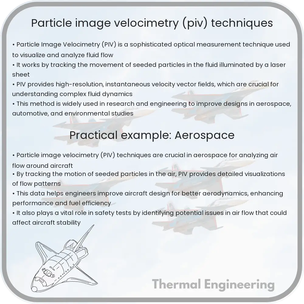
Particle Image Velocimetry (PIV) is an advanced optical technique used to measure fluid flow velocities by tracking seeded tracer particles.

Particle image velocimetry (PIV) techniques

Understanding Particle Image Velocimetry (PIV)

Particle Image Velocimetry (PIV) is a sophisticated optical measurement technique used primarily in fluid dynamics to measure velocities and related properties in fluids. It is invaluable for researchers and engineers alike, as it provides detailed quantitative data in a non-intrusive way, enabling the study of flow characteristics without altering the flow itself.

How PIV Works

PIV involves illuminating a specific region of fluid with a laser sheet, and seeding the fluid with tracer particles which are assumed to follow the flow dynamics accurately. A camera (or multiple cameras) is used to capture images of the particles at two different times. The displacement of the particles between these times is then measured, and from this data, the flow velocity can be calculated.

Key Components of PIV

  • Laser: A high-power laser is used to create a thin light sheet that illuminates the particles in the fluid. Commonly, lasers like Nd:YAG or Argon-Ion are used due to their high intensity and ability to emit light at specific, visible wavelengths.
  • Seeding Particles: Particles such as small polystyrene or glass spheres, typically ranging from 1 to 10 micrometers in diameter, are introduced into the flow. They must be neutrally buoyant to accurately follow the fluid’s flow and sufficiently reflective to stand out in the laser illumination.
  • Cameras: High-resolution cameras equipped with appropriate filters (to block out unwanted light and only capture the wavelength of the laser) are used. The timing between the captured frames is critical and depends on the flow velocities.

Measuring the Flow Velocity

Once the images are captured, digital image processing techniques are applied. The basic principle is to divide the images into small interrogation windows and to compute the displacement of particle patterns within these windows from the first to the second image.

The typical computational method used is cross-correlation, which evaluates the similarity of particle pattern positions between the two exposures. By finding the peak of the correlation function, the displacement of particle images can be determined. The velocity (v) can then be calculated using the equation:

v = d/Δt

  • d: Displacement of the particle images between the two exposures.
  • Δt: Time interval between the two exposures.

Applications of PIV

PIV is utilized in a variety of fields such as:

  • Aerodynamics testing (e.g., around aircraft wings or automotive components)
  • Studies of blood flow in medical research
  • Environmental studies (e.g., flow of water in rivers or pollution dispersion)
  • Turbulence research and fluid mechanics education

PIV delivers a wealth of detailed information that allows engineers and scientists to visualize and understand complex fluid flows and turbulence patterns. Its ability to provide instantaneous velocity fields with high spatial resolution makes it an indispensable tool in the exploration of fluid dynamics across various applications.

Conclusion

Particle Image Velocimetry represents a blend of optical technology, advanced imaging techniques, and digital image processing, culminating in a powerful tool for the analysis of fluid flow. As technology progresses, the applications of PIV continue to expand, leading to deeper insights and innovations in fluid dynamics research and many related fields.

Computational fluid dynamics (CFD) for HVAC optimization

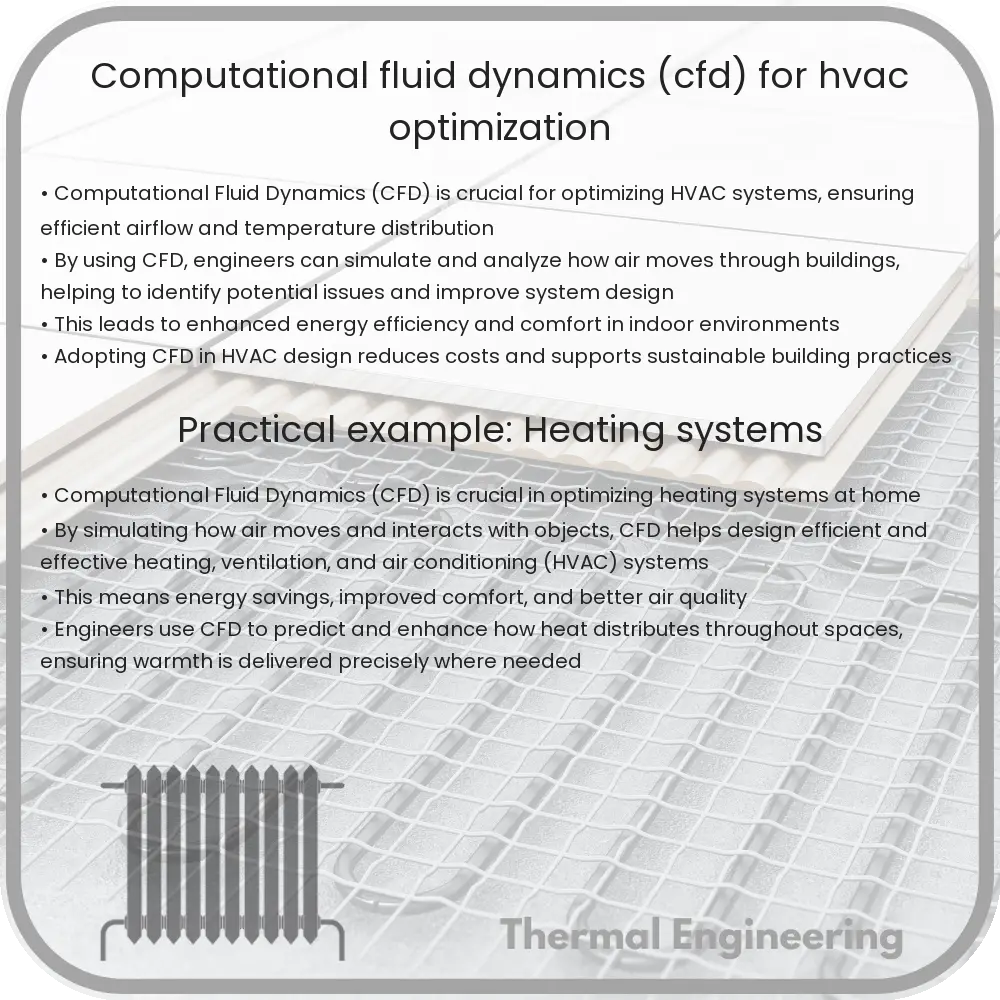
Learn how Computational Fluid Dynamics (CFD) enhances HVAC system efficiency by optimizing airflow, temperature regulation, and energy use.

Computational fluid dynamics (CFD) for HVAC optimization

Understanding Computational Fluid Dynamics (CFD) in HVAC Optimization

Heating, Ventilation, and Air Conditioning (HVAC) systems are an essential component of residential, industrial, and commercial buildings, ensuring a comfortable and safe environment. The optimization of these systems for efficiency and effectiveness is paramount, and here, Computational Fluid Dynamics (CFD) plays a vital role.

What is Computational Fluid Dynamics (CFD)?

Computational Fluid Dynamics (CFD) is a branch of fluid mechanics that uses numerical analysis and data algorithms to solve and analyze problems involving fluid flows. The method utilizes computational software to simulate the interaction of liquids and gases with surfaces defined by boundary conditions. By using CFD, engineers can model the flow of air, heat transfer, and other related physical phenomena in virtual environments without the need for costly experimental testing.

Application of CFD in HVAC Systems

CFD allows engineers to optimize HVAC systems by providing detailed visualizations of how air flows through ducts, around equipment, and within occupied spaces. The primary goal is to enhance thermal comfort and improve the quality of indoor air, while minimizing energy consumption. Here are some ways CFD contributes to HVAC optimization:

  • Airflow Optimization: CFD simulations help in designing ductwork that maximizes air distribution while minimizing energy losses. This is crucial for maintaining uniform temperatures and adequate air circulation throughout the space.
  • Temperature Regulation: By simulating various scenarios, CFD helps in understanding how heat transfer occurs within different building spaces. These insights are essential for the optimal placement of heating and cooling elements.
  • Contaminant Control: CFD is used to study the movement of potential contaminants in an indoor environment. This is particularly important in settings such as hospitals or laboratories, where air quality is tightly controlled.
  • Energy Efficiency: With rising energy costs and environmental concerns, efficiency is a major focus in HVAC design. CFD provides a framework to study and implement energy-saving measures effectively.

Steps Involved in CFD Analysis for HVAC

  1. Problem Definition: Clearly define the scope of the study, including the expected outcomes and limitations.
  2. Model Creation: Develop a geometric model of the HVAC system, which includes ducts, vents, and other key components.
  3. Meshing: Divide the model into small, discrete cells that the simulation will use to solve the fluid flow equations.
  4. Setup and Solution: Input boundary conditions (e.g., inflow velocity, temperature) and physical models, then run the simulation to solve the governing equations.
  5. Data Analysis: Evaluate the results for velocity fields, temperature distribution, particle tracking, etc., and reinterpret them to suggest practical solutions.

Adopting CFD in the design and development phase of HVAC systems can substantially decrease the risk of costly modifications after installation and provide systems that operate more efficiently from the start. Advances in computational power and the development of user-friendly software continue to diminish barriers, making CFD a more accessible and powerful tool than ever before. Continued innovation in both CFD techniques and HVAC technologies predicts a future where optimal indoor environments are achieved with minimal environmental impact.

In summary, the integration of CFD in HVAC system design and optimization helps in achieving superior air quality and thermal comfort, promotes energy efficiency, and supports the sustainability goals of the modern world.

Boundary layer theory applications

Boundary layer theory is a fundamental principle of fluid dynamics essential in engineering and physics, impacting everything from aerospace to environmental systems.

Boundary layer theory applications

Understanding Boundary Layer Theory and Its Applications

Boundary layer theory is a fundamental aspect of fluid dynamics, which describes the behavior of fluid flow at a boundary. Introduced by Ludwig Prandtl in the early 20th century, this concept has revolutionized our understanding of how fluids behave when they come into contact with surfaces. With its principles heavily relied upon in both engineering and physics, boundary layer theory plays a critical role in a myriad of applications ranging from aerospace engineering to everyday household systems.

Basic Concepts of Boundary Layer Theory

The boundary layer is the thin region of fluid lying close to the boundary (the surface of an object through which the fluid is moving) and is where the fluid experiences viscous forces. Outside the boundary layer, the flow is typically inviscid (viscosity is negligible), making the flow dynamics simpler and governed primarily by pressure forces. The boundary layer can be characterized by its thickness, in which the velocity of the fluid transitions from zero at the surface (due to the no-slip condition of viscous fluids) to a value close to that of the free stream at its outer edge.

Applications in Engineering

  • Aerospace Engineering: In aerospace engineering, managing the boundary layer is crucial for the efficient performance of aircraft. Controlling the boundary layer helps in reducing drag, thus improving fuel efficiency and aircraft performance. Technologies like boundary layer suction and vortex generators are used extensively to control airflow around wings and fuselage.
  • Automotive Engineering: Similar to aerospace, in automotive engineering, controlling the boundary layer can lead to reductions in drag, which improve the fuel efficiency of vehicles. Car designers use various techniques, such as aerodynamic shaping and the addition of spoilers, to manage boundary layers effectively.
  • Maritime Engineering: Ship hulls are designed considering the boundary layer to minimize resistance between the water and the hull surface, improving speed and reducing energy consumption.
  • Turbomachinery: In turbines and compressors, the boundary layer’s behavior impacts the efficiency and stability of these machines. Techniques such as blade shaping and the use of casing treatments are employed to control boundary layer effects and enhance performance.
  • Building and Environmental Engineering: Boundary layer theory helps in predicting how pollutants will spread in the atmosphere or water, aiding the design of ventilation systems in buildings and the assessment of environmental impacts of various pollutants.

Conclusion

Boundary layer theory is not just an academic topic but a practical tool used in many fields of engineering. By understanding how the boundary layer works and developing methods to control it, engineers can design more efficient machines and structures, leading to advancements in technology and improvements in performance. From enhancing the speed and efficiency of vehicles and aircraft to understanding environmental impacts, boundary layer theory remains a cornerstone of fluid dynamics applications.

As research continues and technology advances, boundary layer management will continue to evolve, offering new challenges and opportunities in engineering and science alike.

Thermal comfort in green buildings

Explore how thermal comfort in green buildings enhances occupant well-being and energy efficiency through design and technology.

Thermal comfort in green buildings

Understanding Thermal Comfort in Green Buildings

Thermal comfort describes the state of mind that expresses satisfaction with the surrounding environment (ASHRAE Standard 55). In the context of green buildings, achieving thermal comfort for occupants is a key goal, as it not only contributes to their well-being and productivity but also impacts the building’s overall energy efficiency. Green buildings, designed to be resource-efficient and environmentally responsible throughout their life-cycles, integrate various strategies to maintain optimal thermal conditions.

Factors Influencing Thermal Comfort

Thermal comfort is influenced by both environmental and personal factors including:

  • Air temperature: The most straightforward measure, impacting how hot or cold a space feels.
  • Radiant temperature: The heat emitted by surfaces in a room, which can affect comfort even if the air temperature is moderate.
  • Air velocity: Increased air movement can enhance comfort during higher temperatures by promoting sweat evaporation.
  • Humidity: High humidity can inhibit sweat evaporation, making temperatures feel warmer than they are.
  • Metabolic rate: The rate at which a person generates heat through activity.
  • Clothing insulation: Heavily influences how much heat is retained or lost by the body.

It’s also important to remember that thermal comfort is subjective and can vary widely between individuals, influencing their perceptions and expectations.

Strategies for Achieving Thermal Comfort in Green Buildings

Green buildings employ various strategies aimed at achieving efficient and sustainable thermal comfort, such as:

  • Building orientation and design: Proper orientation of a building reduces excessive heat gain and loss, making use of natural light and insulation.
  • Use of thermal mass: Materials that have high thermal mass, like concrete or brick, can absorb and store excess heat, releasing it slowly to minimize temperature fluctuations.
  • Advanced insulation: High-quality insulation helps maintain consistent internal temperatures regardless of external weather conditions.
  • Energy-efficient HVAC systems: These systems are designed to maintain comfort using less energy. This includes high-performance windows and efficient heating and cooling systems.
  • Natural ventilation: Makes use of wind and thermal buoyancy to cool buildings naturally, decreasing reliance on air conditioning systems.
  • Smart building technologies: Utilize sensors and automated systems to adjust conditions based on real-time data such as occupancy and weather changes.

Each strategy is tailored to the specific climate and context of the building, emphasizing the importance of holistic design and operation approaches in green building projects.

Impact of Thermal Comfort on Sustainability

Improving thermal comfort in green buildings significantly enhances sustainability. Efficient management of a building’s thermal environment reduces the need for mechanical heating and cooling, decreasing energy consumption and associated carbon emissions. Furthermore, thermal comfort supports the health and productivity of building occupants, a fundamental aspect of social sustainability.

In summary, the pursuit of thermal comfort in green buildings aligns directly with the goals of environmental responsibility and efficiency. By focusing on both innovative technologies and traditional design principles, green buildings can ensure that occupant comfort and ecological sustainability go hand in hand.

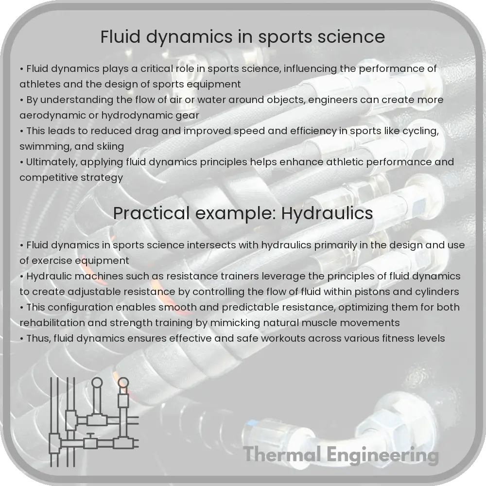
Fluid dynamics in sports science

Explore the application of fluid dynamics in enhancing sports performance and equipment design, highlighting key principles like drag force and Reynolds Number.

Fluid dynamics in sports science

Understanding Fluid Dynamics in Sports Science

Fluid dynamics, a sub-discipline of fluid mechanics, explores how fluids (liquids and gases) behave under varying conditions of flow and force. In sports science, this understanding is crucial as it affects everything from the design of sports equipment to the performance of athletes. This article sheds light on how principles of fluid dynamics are applied to enhance athletic performance and equipment design.

Key Principles of Fluid Dynamics

Before diving into specific applications in sports, it’s important to grasp some foundational concepts of fluid dynamics:

  • Laminar and Turbulent Flow: Fluid flow is categorized into laminar (smooth and regular) or turbulent (chaotic and irregular). Athletes and equipment designers aim to reduce turbulence to decrease resistance and improve efficiency.
  • Drag Force: This force opposes an object’s motion through a fluid. Calculated as FD = 1/2 * ρ * v2 * CD * A, where ρ is the fluid density, v is velocity, CD is the drag coefficient, and A is the cross-sectional area.
  • Reynolds Number (Re): This dimensionless number helps predict flow patterns in different fluid flow situations. It’s defined as Re = ρ * v * L / μ, where L is the characteristic length and μ is the dynamic viscosity of the fluid.

Applications in Sports

The principles of fluid dynamics find multiple applications in sports, enhancing both athlete performance and the design of sports gear:

  1. Swimming: In swimming, reducing drag is essential. Swimmers wear caps and suits that are designed to be hydrodynamic, minimizing the turbulent wake and reducing friction. Moreover, techniques and body positions are optimized to maintain laminar flow around the body, thus decreasing drag.
  2. Cycling: Cyclists also benefit significantly from fluid dynamics. Aerodynamic helmets and streamlined bike frames are designed to reduce air resistance. Team strategies, like drafting, where cyclists ride closely behind another to stay in their slipstream, also utilize fluid dynamics to reduce effort and increase speed.
  3. Golf: Golf ball design is heavily influenced by fluid dynamics. The dimples on a golf ball create a turbulent boundary layer that allows the ball to travel further than a smooth ball by reducing pressure drag and enhancing lift.
  4. Athletics: Track athletes wear tightly fitted clothing to reduce air resistance. Hurdles are designed with aerodynamic features to ensure that the air flows smoothly around them, minimizing the impact on a runner’s speed as they leap over.

Moreover, computational fluid dynamics (CFD) simulations are increasingly used in sports to model scenarios and refine equipment design. These simulations help in understanding how modifications to equipment can affect an athlete’s performance by visually representing airflow and predicting how changes in design alter fluid dynamics.

Challenges and Future Directions

Despite many advancements, challenges remain. Accurately predicting and optimizing fluid dynamics in sports is complex due to the variability in human movement. Future research aims to personalize equipment and refine techniques further based on individual athletes’ interactions with fluids.

Fluid dynamics continues to be a vital area in sports science, with ongoing research and development paving the way for more innovative applications that push the boundaries of what athletes can achieve. Understanding these principles not only enhances performance but also contributes to the safety and effectiveness of sports practices.

Environmental fluid mechanics

Explore the principles and applications of environmental fluid mechanics in managing ecological challenges and promoting sustainable development.

Environmental fluid mechanics

Understanding Environmental Fluid Mechanics

Environmental fluid mechanics is a fascinating branch of engineering that deals with the study of fluid motions like flow and transport processes in the environment. It incorporates principles from fluid mechanics, hydrology, and meteorology to understand how fluids behave in natural settings, influencing everything from air pollution dispersion to water purification systems. This field is essential for managing environmental challenges and ensuring sustainable development.

Key Concepts of Environmental Fluid Mechanics

The foundation of environmental fluid mechanics is built on several key concepts:

  • Fluid Properties: Understanding the properties of fluids, including density, viscosity, and temperature, is crucial in predicting how they will behave under different environmental conditions.
  • Flow Dynamics: This involves studying how fluids move in various environments, which can be affected by obstacles, terrain variations, and interactions with other fluids.
  • Conservation Laws: These are fundamental principles governing mass, momentum, and energy in fluid flows. They are essential for developing mathematical models to predict fluid behavior.
  • Turbulence: Most environmental flows are turbulent. Understanding turbulence and its effects on the transport and dispersion of substances in fluids is vital for accurate modeling and prediction.

Applications in Environmental Engineering

Environmental fluid mechanics has a wide range of applications in environmental engineering:

  • Water Treatment: Engineers use fluid mechanics to design systems that optimize the flow of water through filters and other cleaning processes to remove pollutants effectively.
  • Air Quality Management: Understanding how pollutants disperse in the atmosphere helps engineers create better strategies to reduce air pollution.
  • Erosion Control: Fluid mechanics is crucial in predicting how water will erode landscapes, helping to design effective soil conservation practices and structures.
  • River Engineering: The study of fluid flow in rivers helps in the design of dams, levees, and channels to manage floodwaters and maintain navigability.

Challenges and Future Directions

Despite its advancements, environmental fluid mechanics faces several challenges:

  • Scaling: Translating laboratory-scale experiments to natural, large-scale environments often introduces complexity and uncertainty.
  • Climate Change: The impacts of climate change on fluid dynamics, especially in hydrological cycles and weather patterns, require ongoing adaptation of current models and theories.
  • Interdisciplinary Integration: Collaborating effectively across disciplines is necessary to address the multifaceted issues of environmental management.

As we move forward, the integration of more precise sensors and advanced computational models offers exciting prospects for more accurate simulations and predictions. This progress will enhance our ability to manage and protect our environmental resources more effectively.

In conclusion, environmental fluid mechanics plays a pivotal role in our understanding and management of the natural world. Its principles and applications are crucial for solving some of today’s most pressing environmental issues, making it an indispensable field of study and practice.

Fluid dynamics in process engineering

Fluid dynamics” refers to the study of fluid behavior—liquids and gases—under varying conditions of flow, pressure, and temperature, essential in process engineering.

Fluid dynamics in process engineering

Understanding Fluid Dynamics in Process Engineering

Fluid dynamics is a sub-discipline of fluid mechanics that describes the flow of fluids—liquids and gases. It is crucial in process engineering, which involves designing and operating units for manufacturing chemical products or transforming raw materials. This article explores the basics of fluid dynamics and its practical applications in process engineering.

Core Concepts of Fluid Dynamics

At its core, fluid dynamics is concerned with understanding how fluids behave under various conditions of flow, pressure, and temperature. The fundamentals of fluid dynamics are based on three primary principles:

  • Conservation of Mass: Also known as the continuity equation, it reflects that mass cannot be created or destroyed within a closed system. The equation can be expressed as ∆m = ρ * A * v = constant, where ρ is the density, A is cross-sectional area, and v is velocity.
  • Conservation of Momentum: Represented by Newton’s Second Law, it states that the force exerted on a fluid mass is equal to the mass of the fluid multiplied by the acceleration. It is typically analyzed using Euler’s or Navier-Stokes equations.
  • Conservation of Energy: Implies that energy can neither be created nor destroyed. In fluid dynamics, this is often expressed through Bernoulli’s equation for incompressible flow: P1 + 0.5 * ρ * v21 + ρ * g * h1 = P2 + 0.5 * ρ * v22 + ρ * g * h2, where P is pressure, v is flow velocity, g is gravity, and h is height.

These principles guide engineers in designing processes that involve the efficient transfer and transformation of liquids and gases.

Applications in Process Engineering

Fluid dynamics plays a vital role in many aspects of process engineering, such as:

  • Piping Systems: Design and analysis of pipe flows are crucial for ensuring smooth, efficient transport of fluids without incurring excessive pressure losses.
  • Chemical Reactors: Fluid dynamics helps in the design of reactors where gases or liquids react to form products. Efficient mixing and heat transfer are crucial for the yield and selectivity of the reactions.
  • Heat Exchangers: These devices transfer heat between two or more fluids at different temperatures. Fluid dynamics assists in analyzing the heat transfer coefficients and the overall heat transfer to ensure optimal design.
  • Separation Processes: Processes like distillation and filtration depend on fluid dynamics to improve the efficiency of separating mixtures into their individual components.

Each application uses the principles of fluid dynamics to optimize process design, control flow rates, maximize energy efficiency, and ensure safety in industrial operations.

Challenges and Innovations

Despite its established principles, fluid dynamics in process engineering continues to face challenges, particularly in turbulent flow management, multi-phase flow analysis, and reacting flows. Computational Fluid Dynamics (CFD) has emerged as a powerful tool for visualizing and solving complex fluid flow problems, often in conjunction with experiments and theoretical analyses.

The integration of advanced algorithms and machine learning techniques with CFD is paving the way for more sophisticated and precise models, which can predict and control processes in near-real-time. This innovation not only improves the efficiency and safety of chemical processes but also leads to significant economic and environmental benefits.

Understanding and applying fluid dynamics is essential for any process engineer aiming to optimize industrial processes and equipment designs. The field is continually evolving with technological advances, ensuring its relevance and application in solving some of the most challenging problems in chemical engineering.

Heat transfer in fluid flows

Learn about heat transfer in fluid flows, its modes, and its critical role in engineering systems like HVAC and aerospace.

Heat transfer in fluid flows

Understanding Heat Transfer in Fluid Flows

Heat transfer in fluid flows is a fundamental concept in engineering that influences various applications, from industrial processes to everyday appliances. This happens throughout systems where fluids—such as gases or liquids—are used to transfer energy. Understanding this concept is crucial for designing efficient systems in automotive, aerospace, HVAC (heating, ventilation, and air conditioning), and many other fields.

Three Modes of Heat Transfer

Heat transfer occurs in three primary modes: conduction, convection, and radiation. In the context of fluid flows, convection is the most relevant mode.

  • Conduction – Direct heat transfer through material without the movement of the substance itself.
  • Convection – Heat transfer due to the motion of fluid. This can be either natural or forced convection, depending on whether the fluid motion is generated by external means (like a pump or fan) or by buoyant forces arising from density differences caused by temperature variations in the fluid.
  • Radiation – Transfer of energy through electromagnetic waves, which does not require a medium.

Convection in Fluid Flows

Convection is split into two further categories:

  1. Natural convection occurs when fluid motion is caused by buoyancy forces that are due to density variations in the fluid with temperature. For instance, warm air rises because it is less dense than cooler air.
  2. Forced convection involves fluid motion driven by external sources, like pumps or fans. Examples of this can be seen in water cooling systems in nuclear reactors or forced air systems in home heating.

The Governing Equation

The rate of convective heat transfer can be described by Newton’s law of cooling:

\[
q = h * A * (T_{\text{fluid}} – T_{\text{surface}})
\]

Where:

  • \(q\) represents the heat transfer rate in watts,
  • \(h\) is the heat transfer coefficient in watts per square meter Kelvin,
  • \(A\) refers to the heat transfer area in square meters,
  • \(T_{\text{fluid}}\) is the temperature of the fluid, and
  • \(T_{\text{surface}}\) is the temperature of the surface in contact with the fluid.

Factors Influencing Heat Transfer in Fluids

Several factors impact the efficiency of heat transfer in fluid flows:

  • Temperature difference – Greater temperature differences can enhance the heat transfer rate.
  • Fluid velocity – Higher velocities generally increase the heat transfer rate by minimizing the thickness of the thermal boundary layer, a layer of fluid that is significantly affected by the thermal energy of the surface.
  • Thermal properties – These include thermal conductivity, specific heat capacity, and density of the fluid. Each of these properties can affect how effectively a fluid can carry and transfer heat.
  • Surface area – Larger surface areas allow for more extensive contact with the fluid, hence enabling higher rates of heat transfer.
  • Type of fluid flow – Laminar flows, which are smooth and orderly, tend to transfer heat less effectively compared to turbulent flows, which are chaotic and mixed.

Applications in Engineering

Understanding heat transfer in fluid flows enables engineers to design more effective systems across a variety of fields. For example:

  • Automotive engineers design cooling systems to manage engine temperature.
  • Aerospace engineers work on thermal management systems to protect spacecraft from extreme temperatures.
  • Environmental engineers might develop water circulation systems for natural bodies of water to manage ecosystems.

In conclusion, mastering the dynamics of heat transfer in fluid flows is essential for engineering efficient and effective systems in multiple industrial applications. The principles discussed provide foundational knowledge that helps engineers make informed decisions in their respective fields.

Flow measurement techniques in research

Learn about the essential techniques and devices used for measuring fluid flow in engineering, including differential pressure, positive displacement, and more.

Flow measurement techniques in research

Understanding Flow Measurement Techniques in Engineering Research

Flow measurement is a critical component in various engineering fields such as chemical, mechanical, and civil engineering. Accurate measurement of fluid flow is essential for research and practical applications to ensure efficiency, safety, and compliance with environmental standards. This article explores the most widely used techniques for measuring fluid flow in research and their typical applications.

Types of Flow Measurement Devices

There are several methods used to measure fluid flow, each with its advantages, limitations, and field of application. These methods are broadly categorized into differential pressure, positive displacement, velocity, open channel, and mass flow measurements.

  • Differential Pressure Flow Meters
  • This type of flow meter measures the drop in pressure across an obstruction inserted in the flow path. The most common examples include orifice plates, Venturi tubes, and flow nozzles. According to the Bernoulli Principle, an increase in the speed of the fluid occurs simultaneously with a decrease in pressure. The flow rate can be derived from the measured pressure drop using the equation:

    Q = C * A * sqrt((2 * ΔP) / ρ)

    where Q is the flow rate, C is the discharge coefficient, A is the cross-sectional area, ΔP is the pressure drop, and ρ is the fluid density.

  • Positive Displacement Meters
  • These devices measure the flow rate by mechanically measuring the volume of fluid moving through the meter. They are ideal for viscous fluids and are used in applications requiring precise volumetric flow measurements, such as fuel metering.

  • Velocity Meters
  • Velocity meters, such as turbine, ultrasonic, and electromagnetic flow meters, calculate the flow rate by measuring the fluid’s velocity and then multiplying by the cross-sectional area of the pipe. An example equation used by ultrasonic flow meters, which measure the transit time of sound waves affected by the flow velocity, is:

    v = (d * (tup – tdown)) / (2 * tup * tdown)

    where v is the flow velocity, d is the distance between ultrasonic transducers, and tup and tdown are the transit times up and downstream, respectively.

  • Open Channel Flow Meters
  • Used primarily for measuring flow in rivers, canals, and sewers, these meters typically use structures like weirs and flumes. The flow rate can be calculated based on the height of the fluid known as the head over the structure. The flow rate equation for a rectangular weir, for instance, is:

    Q = (2/3) * C * b * H3/2

    where C is the discharge coefficient, b is the width of the weir, and H is the head over the weir.

  • Mass Flow Meters
  • These meters, including thermal and Coriolis flow meters, measure the mass flow rate of a fluid traveling through a tube rather than its volumetric flow rate. They are particularly useful in the chemical industry and for any application where the fluid composition can vary.

Choosing the Right Flow Measurement Technique

Selecting the appropriate flow measurement technology depends on several factors, including the type of fluid, required accuracy, flow range, and environmental factors like temperature and pressure. Engineers must also consider the installation environment and maintenance requirements to ensure sustained accuracy and reliability. Understanding these principles helps in optimizing system performance and achieving more reliable data for engineering research and applications.

With advancements in technology and digital integration, modern flow measurement devices offer improved accuracy, real-time data logging, and easy integration with control systems, expanding their application scope far beyond traditional uses.