Facebook Instagram Youtube Twitter

Hydrodynamic stability of vessels

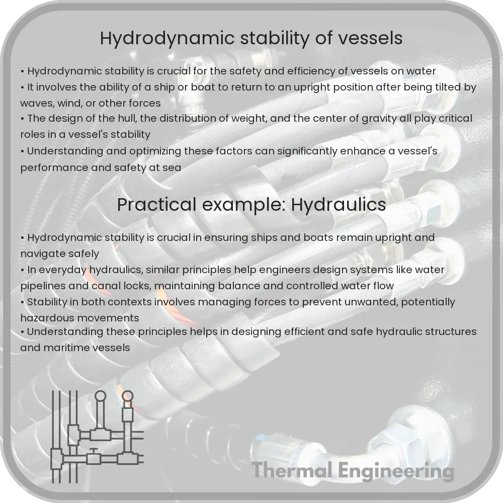
Hydrodynamic stability is vital for the safety and efficiency of maritime vessels, ensuring they maintain equilibrium in challenging conditions.
Hydrodynamic stability of vessels

Understanding Hydrodynamic Stability of Vessels

Hydrodynamic stability plays a crucial role in the design, operation, and safety of maritime vessels. Whether a ship maintains a steady course or capsizes in rough seas can depend on its stability in water. This concept is an intersection of physics and engineering that ensures vessels are not only efficient but also safe to navigate oceans, rivers, and other water bodies.

What is Hydrodynamic Stability?

Hydrodynamic stability refers to the ability of a vessel to return to a state of equilibrium after being disturbed by external forces such as waves, wind, or currents. A vessel that is hydrodynamically stable will resist rolling, pitching, or yawing excessively, which are movements along the ship’s longitudinal, transverse, and vertical axes, respectively.

Factors Influencing Hydrodynamic Stability

  • Center of Gravity: The lower the center of gravity, the more stable the vessel. This is because a low center of gravity helps to counteract the overturning effect of buoyancy, a force exerted by water to keep the vessel afloat.
  • Hull Design: The shape and overall design of the hull affect how water flows around the vessel, influencing its ability to maintain balance and stability in water.
  • Weight Distribution: Proper distribution of weight onboard, including cargo and ballast, is critical to maintaining stability. Uneven weight distribution can cause the vessel to list to one side or become unstable.
  • Metacentric Height: This is a calculated point above the center of buoyancy and indicates stability. A high metacentric height suggests better stability since it increases the vessel’s ability to right itself after tilting.

Mathematics Behind Hydrodynamic Stability

The stability of a floating body like a ship can be assessed by considering moments acting around the center of buoyancy. The primary calculation involves determining the metacentric height (GM), which is defined as:

\[ GM = KB + BM – KG \]

Where:

  • KB is the vertical distance from the keel to the center of buoyancy.
  • BM is the metacentric radius, and it manifests as a function of the moment of inertia (I) of the waterplane area about a transverse axis through the center of buoyancy and the vessel’s displaced volume (V) so, \[ BM = \frac{I}{V} \].
  • KG is the vertical distance from the keel to the center of gravity.

This calculation gives a metric that helps engineers assess whether a ship, if disturbed, will return to its upright position or capsize.

Importance of Hydrodynamic Stability in Naval Architecture

Hydrodynamic stability is essential not just for ship safety but also affects the ship’s fuel efficiency, speed, and overall operability. Naval architects must carefully design ships to ensure they can handle expected sea conditions. Stability analysis involves sophisticated simulations and model testing, often conducted in water tanks before full-scale production.

Challenges in Achieving Hydrodynamic Stability

Modern vessels, especially high-speed crafts and lightweight ships, face significant challenges in maintaining hydrodynamic stability. Sophisticated computational methods and technologies such as stabilization systems, ballast adjustments, and hull modifications are used to enhance stability. However, these solutions must be carefully balanced with other design criteria such as capacity, speed, and fuel efficiency.

Conclusion

The hydrodynamic stability of vessels is a fundamental concept in naval architecture, intertwining physics and engineering disciplines to ensure maritime safety and operational efficiency. As technology advances, new methods to analyze and enhance stability continue to evolve, ensuring that vessels not only meet safety standards but also perform optimally under various environmental conditions.

Marine hydrodynamics for energy extraction

Learn about marine hydrodynamics, key for energy extraction from oceans and rivers, focusing on fluid dynamics and renewable energy technologies.

Marine hydrodynamics for energy extraction

Understanding Marine Hydrodynamics for Energy Extraction

Marine hydrodynamics plays a crucial role in the field of renewable energy. It involves the study of water flow characteristics and their applications in energy extraction from marine environments. Understanding how water moves and interacts with various structures is essential for designing efficient systems to harness energy from oceans and rivers. This form of energy extraction offers a sustainable alternative to fossil fuels, tapping into the vast power of the marine ecosystem.

The Basics of Marine Hydrodynamics

Marine hydrodynamics focuses on the behavior of fluids, particularly water, in the marine environment. It examines factors such as fluid dynamics, wave motion, and the impact of water flows on structures. Engineers use these insights to design equipment and installations that can efficiently convert marine energy into usable power. Such energy sources include wave power, tidal power, and ocean currents.

  • Wave Power: Extracting energy from surface wave motion involves devices that capture the energy of moving water surges.
  • Tidal Power: Utilizes the natural rise and fall of ocean tides caused by gravitational forces exerted by the moon and the sun.
  • Ocean Currents: Harnessing energy from water currents requires understanding the patterns and speeds of these currents, influenced by wind, temperature, and the earth’s rotation.

Key Principles in Marine Hydrodynamics

Several core principles define marine hydrodynamics and enable its application in engineering solutions:

  • Bernoulli’s Principle: This principle states that an increase in the speed of a fluid occurs simultaneously with a decrease in pressure or the fluid’s potential energy. It’s essential in understanding water flow behaviors around turbines.
  • Continuity Equation: It expresses the principle of conservation of mass, stating that the mass flow rate through a conduit is constant. For a fluid incompressible like water, this implies that the velocity of flow increases as the cross-sectional area of the flow decreases.
  • Navier-Stokes Equations: These equations describe how the velocity field of fluid flows react to forces such as gravity and turbulence. Solutions to these equations are critical in designing effective marine energy extraction structures.

Technological Applications of Marine Hydrodynamics

The practical application of marine hydrodynamics principles has led to the development of a variety of technologies and structures designed to maximize energy extraction from marine environments:

  1. Tidal Barrages: These large scale structures are used to convert tidal energy into electrical energy. They work by capturing the potential and kinetic energy generated by the change in height (or head) and speed of tidal currents.
  2. Wave Energy Converters: Devices that convert mechanical power produced by the motion of surface waves into electrical power. Different technologies such as point absorbers, oscillating water columns, and attenuators are used, depending on the wave characteristics and site specifics.
  3. Ocean Current Turbines: Similar to wind turbines, these extract energy from underwater currents but must be engineered to withstand the dense marine environment and corrosive saltwater.

Challenges and Future Prospects

Despite significant advancements, the extraction of marine energy faces various challenges. Issues such as environmental impact, high capital costs, and the maintenance of underwater equipment pose substantial hurdles. Furthermore, the variable intensity of waves and tidal patterns can make energy output inconsistent. Nonetheless, ongoing research and technological improvements continue to enhance the viability and efficiency of marine energy systems, promising a more sustainable future powered by the sea.

As our understanding of marine hydrodynamics deepens and technology advances, the full potential of marine energy offers an exciting frontier in renewable energy, destined to play a critical role in the global energy mix.

In conclusion, the field of marine hydrodynamics not only enriches our understanding of the natural world but also equips us with the capability to harness its power in sustainable, innovative ways that were once unimaginable.

Cavitation in hydraulic systems

Learn about cavitation in hydraulic systems, its causes, effects, and prevention strategies.

Cavitation in hydraulic systems

Understanding Cavitation in Hydraulic Systems

Cavitation in hydraulic systems is a phenomenon that occurs when the pressure in a liquid suddenly drops below its vapor pressure and vapor bubbles form in the fluid. These bubbles can collapse violently when they encounter higher pressure regions, causing noise, vibrations, and even damage to equipment. Understanding cavitation is crucial for the design and maintenance of efficient and long-lasting hydraulic systems.

Causes of Cavitation

The primary cause of cavitation is a rapid drop in pressure which can happen due to several reasons:

  • Sudden changes in flow velocity: Fast changes in the speed at which the fluid is moving, often due to pump operation or sudden closure of valves, can drastically decrease pressure.
  • High fluid temperatures: As the temperature of the fluid increases, its vapor pressure rises, making it more susceptible to cavitation.
  • Blockages or restrictions: Partial blockages or sharp bends in the system can lead to localized drops in pressure as the fluid accelerates around these obstructions.

Effects of Cavitation

The collapse of vapor bubbles within hydraulic systems is not a quiet affair. The impacts include:

  • Noise and vibration: The collapse of cavitation bubbles is noisy and can induce vibrations throughout a hydraulic system, which may lead to fatigue in materials.
  • Damage to components: The intense pressure and temperature increase during bubble collapse can physically pit and erode surfaces such as impellers, pump housing, and pipe walls.
  • Reduced efficiency: Cavitation causes a reduction in fluid flow efficiency, leading to higher energy consumption or lower output than expected.

Preventing and Managing Cavitation

To minimize the risk and effects of cavitation, several strategies can be implemented:

  • Maintaining adequate pressure: Designing systems to ensure that pressures do not fall below vapor pressures at any point is fundamental. This might involve selecting suitable pump sizes, adjusting the height of the pump relative to the fluid surface, and avoiding excessive fluid temperatures.
  • Proper system design: Smooth, gradual changes in the cross-sectional area of pipes and careful placement of valves and bends can help manage fluid speeds and reduce the occurrences of pressure drop.
  • Pump throttling: Controlling the operation speed of the pump to match system needs can prevent unnecessary drops in pressure.
  • Regular maintenance: Ensuring that components are not worn or damaged and that there are no partial blockages in the system helps maintain stable pressure levels.

Conclusion

Cavitation can pose significant challenges in hydraulic systems, potentially leading to damage and decreased operational efficiency. Through understanding the causes and effects of cavitation, engineers can design more robust systems and implement measures to prevent this destructive phenomenon. Regular maintenance and careful monitoring of operating conditions are key to managing cavitation effectively in existing systems.

In conclusion, addressing cavitation is pivotal for sustaining the health and efficiency of hydraulic systems in various engineering applications, from industrial machinery to water treatment facilities.

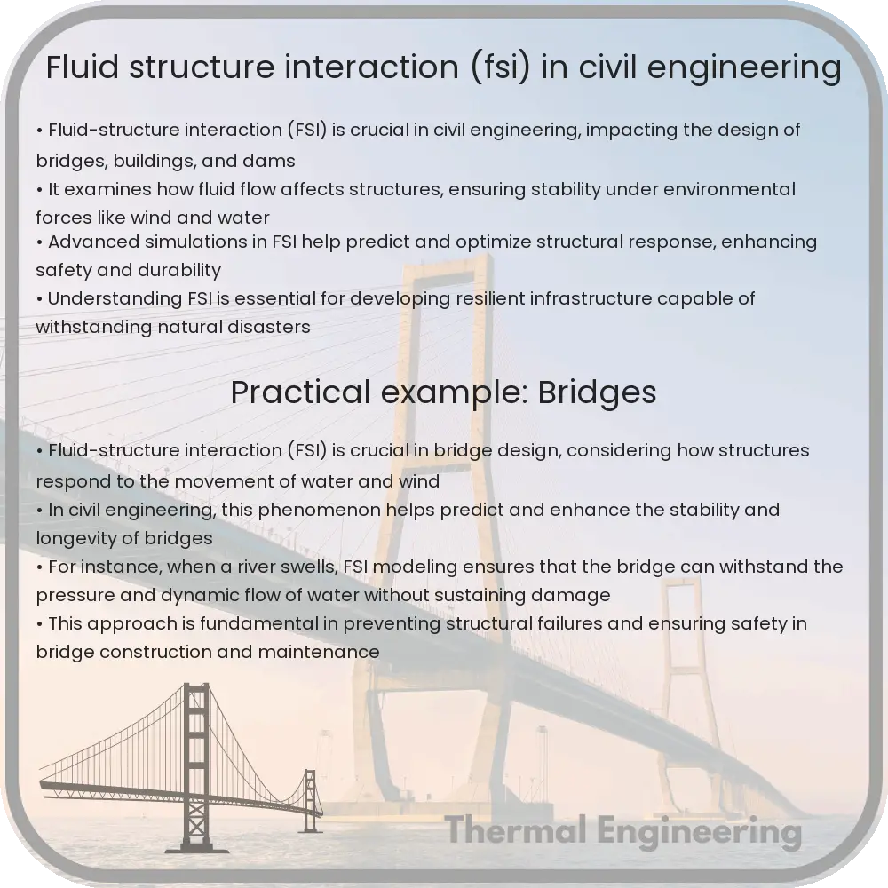
Fluid-structure interaction (FSI) in civil engineering

Fluid-Structure Interaction (FSI) is a fundamental concept in civil engineering, critical for designing safe and enduring structures in fluid environments.

Fluid-structure interaction (FSI) in civil engineering

Understanding Fluid-Structure Interaction (FSI) in Civil Engineering

Fluid-Structure Interaction (FSI) is a crucial consideration in civil engineering, affecting the design and integrity of structures exposed to fluid environments. This interaction occurs when a fluid (such as water or air) comes into contact with a structural element, causing both the fluid and the structure to influence each other’s performance. Understanding FSI is essential for ensuring the safety and longevity of infrastructures like bridges, skyscrapers, offshore platforms, and dams.

Key Concepts in Fluid-Structure Interaction

FSI can be broken down into two main categories: one-way FSI and two-way FSI. One-way FSI means the fluid’s effect on the structure is significant, but the structure’s impact on the fluid flow is negligible. This is common in scenarios where the structure is substantially stiffer than the fluid force. In contrast, two-way FSI means both the fluid dynamics and structural responses significantly affect each other, typical in lightweight or flexible structures.

Importance of FSI in Civil Engineering Projects

Integrating FSI analysis in civil engineering projects helps engineers predict and mitigate potential issues arising from dynamic and potentially destabilizing fluid-structural interactions. Here are some areas where FSI is particularly impactful:

  • Bridges: Wind and water currents can cause vibrations or oscillations in bridge components, affecting stability and structural integrity. This was famously demonstrated in the collapse of the Tacoma Narrows Bridge in 1940, dominated by aerodynamic flutter and torsional oscillations.
  • High-rise Buildings: Skyscrapers are subjected to wind loads that can cause sway, requiring designs that counteract these effects efficiently while maintaining comfort for occupants.
  • Offshore Structures: Platforms and wind turbines face constant interaction with maritime environments, needing robust design strategies to handle forces from waves, sea currents, and wind.
  • Dams and Spillways: Water interactions with dams are complex, involving pressures, undercurrents, and the potential for scouring, all of which must be analyzed for safety assessments.

Methods of Analysis in FSI

Engineering analysis of FSI usually involves computational methods that simulate the interactions between fluids and structures. The most common approaches include:

  • Computational Fluid Dynamics (CFD): Used to simulate fluid flow around and through structures, providing data on pressure, force, and flow patterns.
  • Finite Element Analysis (FEA): Used to simulate structural response to loads, including those imposed by fluid interactions.
  • Coupled CFD and FEA: Integration of both methods provides a more comprehensive analysis, crucial for understanding complex interactions in real-world scenarios.

Advanced software tools enable the simulation of FSI in a virtual environment, allowing for optimization and testing of designs under various scenarios. This reduces physical prototyping costs and potential risks during the construction phase.

Challenges and Innovations in FSI

Despite advancements in technology, FSI analysis remains complex and computationally intensive. The accuracy of simulations heavily depends on the quality of the mathematical models and input parameters used in the software. Ongoing research and innovation in FSI are directed towards developing more robust and efficient computational techniques, multi-scale models, and real-time monitoring technologies for better prediction and management of these interactions.

In conclusion, understanding and mastering Fluid-Structure Interaction is vital in civil engineering, ensuring structures can withstand and function in their fluid environments. As technologies improve, so too will our ability to create safer, more resilient infrastructure in fluid-interactive contexts.

Wind engineering for buildings

Understand the impact of wind on structures and the strategies engineers use to enhance safety and stability in wind-prone areas.

Wind engineering for buildings

Introduction to Wind Engineering for Buildings

Wind engineering is a crucial branch of engineering that focuses on understanding the effects of wind on natural and built environments, particularly buildings and structures. This field combines principles from fluid dynamics, meteorology, and structural engineering to ensure structures can withstand the forces exerted by winds, from gentle breezes to violent storms.

Why Wind Engineering Matters

Wind can impose dynamic and static loads that can significantly impact structural integrity and functionality. Effective wind engineering is vital for designing buildings that are not only safe but also comfortable for occupants. In areas susceptible to strong winds, hurricanes, or tornadoes, wind engineering becomes especially crucial.

The Basics of Wind Forces on Structures

The interaction between wind and buildings is primarily characterized by aerodynamic forces. These forces can be broadly classified into two types:

  • Lift: This is the force exerted perpendicular to the wind direction. It can potentially cause tilting or even lifting of the structure.
  • Drag: This force acts parallel to the wind direction, pushing against the structure and causing strain.

These forces vary depending on a building’s shape, size, and orientation relative to the wind, as well as the wind’s speed and turbulence.

Principles of Wind Engineering

  • Wind Tunnel Testing: This is a critical experimental approach where scale models of buildings are tested under controlled wind conditions to predict the wind loads and responses of the actual structure.
  • Computational Fluid Dynamics (CFD): CFD is a numerical method used to simulate wind flow around buildings to predict wind loads and the effect on structural elements.
  • Building Codes and Standards: Engineers must adhere to local and international building codes that provide guidelines on minimum wind loads. For example, the American Society of Civil Engineers (ASCE) publishes standards such as ASCE 7, which specifies requirements for minimum design loads for buildings and other structures.

Critical Considerations in Wind Engineering

  1. Building’s Natural Frequency: Engineers need to ensure the building’s natural frequency does not resonate with the frequency of vortex shedding caused by winds, as this can lead to oscillations and potential failures.
  2. Aerodynamic Modifications: Adjusting the shape and features of a building can reduce wind loads. For instance, tapered or set-back shapes are often used to minimize wind effects.
  3. Use of Dampers: Installation of tuned mass dampers or similar technologies can reduce building sway and vibration, enhancing structural resilience and occupant comfort.

Case Studies in Wind Engineering

Many high-profile buildings around the world have benefited from advanced wind engineering. For example, the Burj Khalifa in Dubai, currently the tallest building in the world, incorporates a Y-shaped floor plan and a spiraled silhouette that helps to reduce wind forces and vortex shedding, ensuring stability even amid the region’s often harsh winds.

Conclusion

Wind engineering plays an indispensable role in the design and construction of buildings, particularly in wind-prone regions. Through comprehensive testing, modeling, and adherence to stringent standards, engineers can optimize building designs for safety, durability, and comfort. As building technologies and materials advance, so too will the methods and capabilities of wind engineering, continuing to safeguard our built environment against the unpredictable forces of nature.

Vortex-induced vibrations analysis

Learn about vortex-induced vibrations (VIV), the challenges they pose to structures like bridges and pipelines, and the solutions used to mitigate their effects.

Vortex-induced vibrations analysis

Understanding Vortex-Induced Vibrations

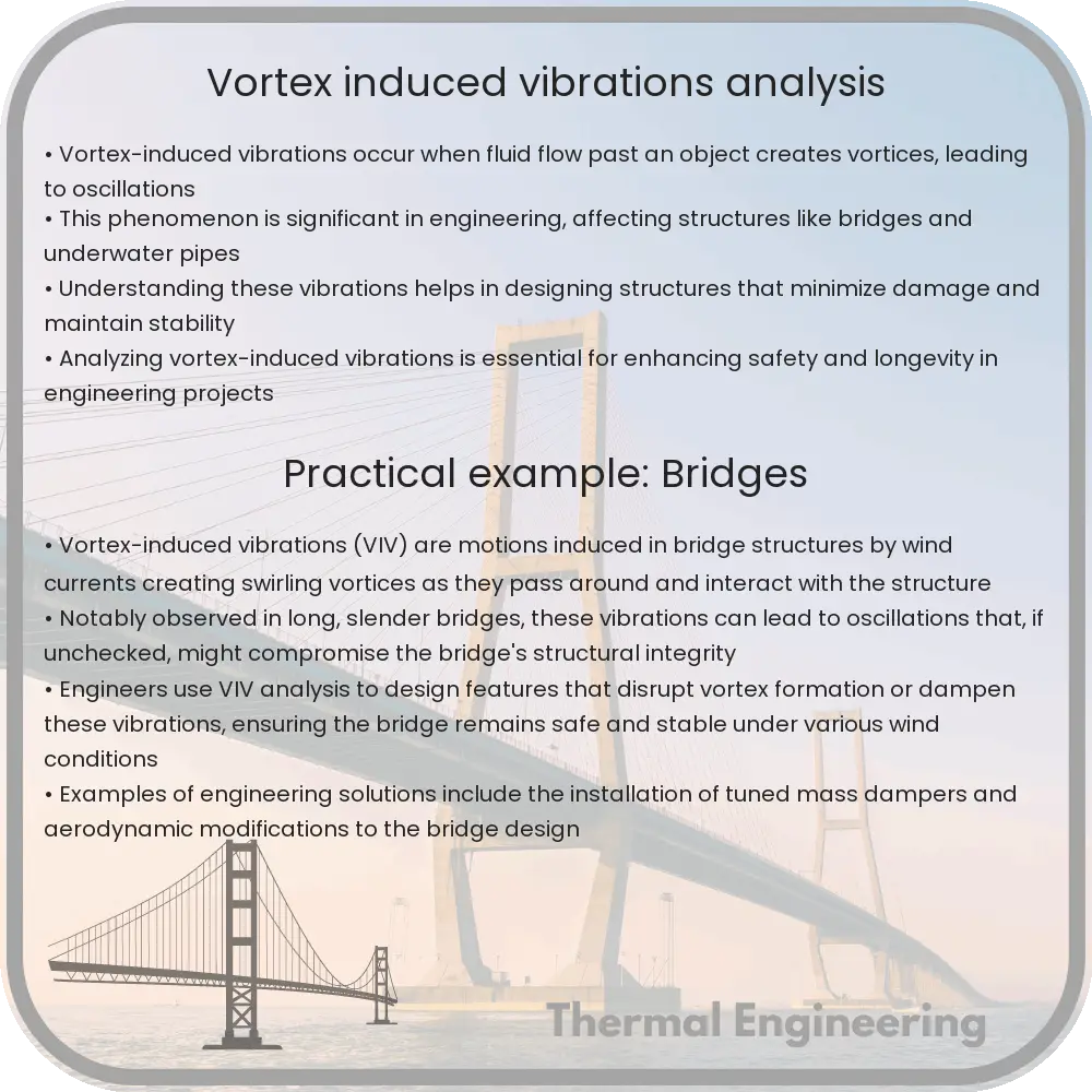
Vortex-induced vibrations (VIV) are motions induced in body structures subjected to fluid flow. The phenomenon is commonly observed in engineering and can affect structures such as skyscrapers, bridges, underwater pipelines, and cables. Understanding VIV is crucial for the design of these structures to prevent potential damage or failure over time.

What Causes Vortex-Induced Vibrations?

When a fluid, such as air or water, flows past a bluff (non-streamlined) body, vortices or swirling flows are shed from the body’s downstream side. This process is known as vortex shedding and is characterized by alternating low-pressure vortices formed on both sides of the body. The pressure differences across the body caused by these vortices lead to fluctuating forces that can induce vibrations in the body.

The frequency at which these vortices shed is known as the shedding frequency, which often depends on the velocity of the fluid flow, the density and viscosity of the fluid, and the dimensions and shape of the body. The shedding frequency can be estimated by the dimensionless Strouhal number (St), given by:

\[
\text{St} = \frac{f \times D}{V}
\]

where:

  • f is the shedding frequency,
  • D is the characteristic diameter, and
  • V is the flow velocity.

Effects of VIV on Structures

VIV can lead to a range of problems for engineering structures, including fatigue damage, reduced structural integrity, and even catastrophic failures. For example, in offshore engineering, VIV is a significant concern for the design and operation of risers and subsea pipelines. The continuous vibrations caused by VIV can fatigue the material, leading to cracks and the eventual failure of the infrastructure.

Preventative Measures and Solutions

Several strategies can be employed to mitigate the effects of VIV in engineering structures:

  • Vortex Suppressors: These are devices attached to the structure that alter the flow around the body to reduce vortex shedding. Common examples include fairings and strakes.
  • Tuned Mass Dampers: These are devices installed in structures to absorb the vibrational energy caused by VIV. By tuning these dampers to the dominant frequency of the vibrations, the impact of VIV can be significantly reduced.
  • Shape Optimization: Modifying the shape of the structure to streamline the flow can drastically reduce VIV. This approach is often used at the design stage of new structures.

Advances in computational fluid dynamics (CFD) and real-time monitoring technologies also allow for improved prediction and management of VIV effects on structures.

Conclusion

Vortex-induced vibrations represent a critical concern in the field of structural engineering, particularly for structures exposed to fluid flows. Through a combination of design innovation and technological solutions, engineers can effectively manage and mitigate the risks associated with VIV, ensuring the longevity and safety of vital infrastructure.

Multiphase flow in porous media

Explore the complexities and applications of multiphase flow in porous media, crucial for engineering fields like petroleum, hydrology, and environmental engineering.

Multiphase flow in porous media

Understanding Multiphase Flow in Porous Media

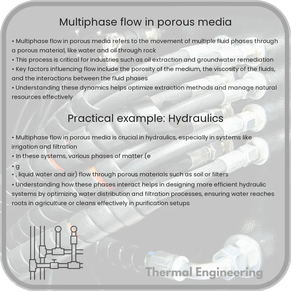
Multiphase flow in porous media is a complex but critical concept in various engineering fields including petroleum engineering, hydrology, and environmental engineering. This process involves the simultaneous flow of multiple fluid phases—such as water, oil, and gas—through a porous geological formation. The interaction between these fluids and the solid matrix significantly influences extraction processes, groundwater contamination, and remediation strategies.

Basic Concepts

Porous media are materials that contain numerous interconnected pores, allowing fluids to pass through them. Examples include soil, sandstone, and coral. The characteristics of the porous medium, such as pore size distribution, porosity, and permeability, play a vital role in determining the flow dynamics of the fluids.

The study of multiphase flow generally focuses on two or more phases, typically distinguishing between wetting and non-wetting fluids based on their affinity to the solid surface. The behavior and distribution of these fluids are governed by a set of physical principles and mathematical equations.

Key Principles and Equations

Key principles involved in the study of multiphase flow include Darcy’s Law for fluid flow in porous media and the concepts of capillary pressure and relative permeability:

  • Darcy’s Law: Originally formulated to describe the flow of a single phase, this law has been extended for multiphase flow. The law states that the flow rate through a porous medium is proportional to the pressure gradient and the permeability of the medium. For flow involving multiple fluids, it’s expressed as:

Q = -K * (dP/dx)

where Q is the flow rate, K is the permeability of the medium, and dP/dx is the pressure gradient.

  • Capillary Pressure (Pc): This is the pressure difference between the wetting and non-wetting fluids due to surface tension and the interaction between the fluids and the solid surface. It’s a key factor in the distribution and movement of fluids in a porous medium.
  • Relative Permeability: This term describes how the presence of multiple fluid phases affects the medium’s ability to conduct each fluid. Typically, the presence of one phase inhibits the flow of the other phase(s).

Applications in Engineering

Understanding and predicting the behavior of multiphase flows in porous media is crucial for several engineering applications:

  • In petroleum engineering, it helps in enhancing oil recovery by efficiently managing water or gas injection into reservoirs.
  • In environmental engineering, it is essential for modeling the transport and fate of pollutants in subsurface environments.
  • In hydrology, it assists in managing aquifer recharge and addressing issues related to water scarcity and groundwater contamination.

Challenges and Future Directions

Despite its importance, modeling multiphase flow in porous media presents several challenges. These include the accurate characterization of porous media, dealing with the scale-dependence of physical properties, and the complex interactions between different fluid phases. Advanced computational models and more accurate experimental methods are continuously being developed to better understand and predict these flows.

As technology advances, so does the potential to enhance recovery processes in petroleum engineering, manage water resources more effectively, and improve pollution remediation strategies. This makes the study of multiphase flow in porous media not only relevant but essential for sustainable development and environmental protection.

Conclusion

Multiphase flow in porous media is a fundamental concept with wide-ranging applications in engineering. By combining principles from physics, chemistry, and engineering, scientists and engineers can better manage natural resources and tackle environmental challenges, making significant contributions to sustainability and efficiency in various sectors.

Low-grade heat utilization

Learn about low-grade heat, its sources, technological approaches for utilization, benefits, and challenges in this detailed guide.

Low-grade heat utilization

Understanding Low-Grade Heat Utilization

Low-grade heat refers to thermal energy available at relatively low temperatures (below 150°C). This type of heat is often considered a low-quality waste because its low temperature limits its direct usability. However, with growing concerns over energy efficiency and environmental sustainability, engineering solutions have been developed to capture and utilize this form of energy, transforming it into useful power.

Sources of Low-Grade Heat

  • Industrial processes: Many industrial activities, including food processing and chemical manufacturing, release heat as a byproduct at low temperatures.
  • Solar thermal energy: Solar collectors can produce heat at these low temperatures, which is often used for heating spaces or water.
  • Geothermal sources: Low-temperature geothermal reservoirs provide a steady supply of heat, typically used directly for heating applications.
  • Waste water treatment: The process of treating wastewater generates heat that is often not utilized.

Technological Approaches to Utilize Low-Grade Heat

Several technologies have been developed to effectively use low-grade heat:

  • Heat Pumps: These devices elevate the temperature of heat from a low to a usable level by consuming external energy. They work on the principle of the vapor compression cycle.
  • Organic Rankine Cycle (ORC): Similar to a conventional steam turbine, the ORC system uses organic fluids with a low boiling point. This allows the system to generate power from lower temperature sources.
  • Adsorption Chillers: These chillers use low-grade heat to drive the adsorption process, cooling water without the need for electrical power.

Benefits of Low-Grade Heat Utilization

  • Energy Efficiency: Utilizing waste heat improves the overall efficiency of energy systems by reducing the need for primary energy sources.
  • Cost Savings: Industries can lower their energy costs significantly by implementing technologies to reclaim and use waste heat.
  • Environmental Impact: By reducing reliance on fossil fuels and decreasing greenhouse gas emissions, low-grade heat utilization contributes positively to environmental protection.

Challenges in Low-Grade Heat Utilization

Despite its potential, the utilization of low-grade heat faces several challenges:

  • Technical Limitations: The efficiency of current technologies to convert low-grade heat into useful energy is often limited, making wide-scale adoption slower.
  • Economic Constraints: The initial investment for technologies like heat pumps or ORC systems can be high, discouraging their adoption, especially in regions with lower energy costs.
  • Geographical Dependencies: The effectiveness of low-grade heat utilization technologies can vary significantly depending on the local climate and the availability of heat sources.

In conclusion, low-grade heat is an underused resource that holds substantial potential for improving energy efficiency and reducing environmental impact. Advances in technology and more favorable economics could further enhance its utilization, presenting an important opportunity in the field of sustainable engineering.

Blood flow simulation in bioengineering

Comprehensive examination of blood flow simulation and its applications in bioengineering, exploring the intersection of computational fluid dynamics, cardiovascular system modeling, and medical advancements.

Blood flow simulation in bioengineering

Blood Flow Simulation in Bioengineering

Blood flow simulation is a crucial aspect of bioengineering, offering insights into the cardiovascular system that can aid in the diagnosis, treatment, and prediction of outcomes in medical conditions. By using computational models, scientists and engineers can analyze the dynamics of blood flow through arteries, veins, and the heart with a degree of precision that is difficult to achieve in experimental setups.

Understanding the Basics of Blood Flow

Blood flow in the human body is driven by the pumping action of the heart, which creates pressure waves in the fluid-contained blood vessels. This flow is influenced by several factors such as blood viscosity, vessel elasticity, and the geometry of the blood vessel network. The complexity of blood flow dynamics, including laminar and turbulent flows, shear stress, and pressure gradients, requires sophisticated mathematical modeling to understand and predict.

The Role of Computational Fluid Dynamics (CFD) in Blood Flow Simulation

Computational Fluid Dynamics (CFD) is a branch of fluid mechanics that uses numerical analysis and algorithms to solve and analyze problems involving fluid flows. In bioengineering, CFD is used to simulate blood flow in the cardiovascular system. This includes the simulation of:

  • Flow patterns within arteries and veins
  • Interactions between blood and vessel walls
  • The impact of arterial plaques or anomalies
  • Heart valve functionality and blood flow dynamics in heart chambers

The fundamental equations governing CFD in blood flow simulations are based on the Navier-Stokes equations, which describe the motion of viscous fluid substances. In the context of blood flow, these equations are often modified to reflect the non-Newtonian properties of blood, among other biological specifics.

Modeling Techniques and Tools

To create accurate models of blood flow, bioengineers use various techniques and tools, including:

  • 1D, 2D, and 3D Modeling: Depending on the level of detail and computational resources, simulations can vary from one-dimensional approximations, useful for large arterial networks, to detailed three-dimensional models for localized studies, such as the interaction of blood with a specific arterial plaque.
  • Particle Methods: Techniques like the Smoothed Particle Hydrodynamics (SPH) are used for modeling blood flow through complex vessel geometries where traditional mesh-based methods face limitations.
  • Software Tools: Many software platforms are available for CFD in bioengineering, such as ANSYS Fluent, COMSOL Multiphysics, and OpenFOAM, each offering unique features for specific types of flow analysis.

Applications of Blood Flow Simulation

The practical applications of blood flow simulation in bioengineering are broad and profoundly impactful. They include:

  • Design and Testing of Medical Devices: Blood flow simulations are essential in the design and testing of medical devices such as stents, bypass grafts, and artificial heart valves. These simulations help in optimizing device performance before actual manufacturing and clinical testing.
  • Surgical Planning: Surgeons can use blood flow simulations to plan complex procedures such as coronary artery bypass surgery, predicting areas of potential complications and improving surgical outcomes.
  • Research and Education: Academic institutions and research facilities use blood flow simulation to study disease mechanisms, such as atherosclerosis development and progression, and for educational purposes, providing students with visual and interactive tools for learning.

In conclusion, blood flow simulation serves as a foundational technology in bioengineering, bridging gaps between theoretical research and clinical application. It brings a deeper understanding of cardiovascular mechanics, enhances the design of medical interventions, and improves patient safety and treatment efficacy.

Aerodynamic drag reduction strategies

Learn about aerodynamic drag reduction strategies, crucial in automotive and aerospace engineering for improved efficiency and performance.

Aerodynamic drag reduction strategies

Understanding Aerodynamic Drag Reduction Strategies

Aerodynamics plays a crucial role in various fields, such as automotive design, aerospace engineering, and even sports, where reducing aerodynamic drag can lead to significant improvements in performance and efficiency. Aerodynamic drag is a resistive force that occurs due to the interaction between a moving object and the air around it. Reducing this drag not only enhances speed but also decreases fuel consumption in vehicles, an essential factor in today’s energy-conscious world.

Basics of Aerodynamic Drag

Drag force can be calculated using the equation:

FD = 0.5 * ρ * v2 * A * CD

Where:

  • FD is the drag force
  • ρ (rho) is the air density
  • v is the velocity of the object relative to the air
  • A is the frontal area of the object
  • CD is the drag coefficient, which depends on the shape of the object and how it interacts with the surrounding air

Reducing any of these factors will result in lower drag, but much of engineering focuses on minimizing the drag coefficient through clever design.

Streamlining

The most straightforward drag reduction strategy is streamlining. Streamlining involves shaping objects so that air flows more smoothly around them, thereby reducing the drag coefficient. This principle is evident in the design of modern cars, aircraft, and even high-speed trains.

Turbulence Minimizers

While it might seem counterintuitive, sometimes introducing controlled turbulence can reduce drag. Devices such as vortex generators on the wings of airplanes or rear spoilers on cars can help in managing airflow to minimize drag effectively. These devices work by making the airflow “stick” to the surface longer, thereby delaying separation and reducing the size of wake vortices, which are a major contributor to drag.

Diminishing Surface Roughness

Surface roughness can increase drag significantly by enhancing turbulent airflow. Reducing roughness, therefore, can reduce drag. This is often seen in automotive painting techniques where multiple coats and sanding result in a very smooth surface, or in the use of special “wraps” for race cars designed to minimize drag.

Active Aerodynamics

Active aerodynamics involve components of a vehicle that can change shape or orientation in response to conditions to minimize drag or maximize downforce (in the case of racing cars). Examples include adjustable rear wings and deployable spoilers. The use of these elements allows for a customized aerodynamic profile that can adapt to speed, wind conditions, and driving demands.

Aerodynamic Wheel Design

Another approach focuses on the design of the wheels, which can influence vehicle aerodynamics significantly. Wheels that are designed with aerodynamic principles in mind can reduce the drag caused by air flowing in and around the wheel wells, which is a notable contributor to overall vehicle drag.

Conclusion

Aerodynamic drag reduction is a vital aspect of modern engineering, contributing to the efficiency and performance of high-speed vehicles and reducing environmental impact by improving fuel economy. By understanding and implementing various strategies, engineers can design objects that interact more efficiently with the air around them, leading to innovations that might redefine what’s possible in aerodynamics.

The journey of mastering aerodynamics is ongoing, and as technology advances, new methods will continue to emerge, making our vehicles faster, more efficient, and environmentally friendly.