Condensation
Source: wikipedia.org CC BY-SA
Similarly as in the previous chapter, in this chapter we will discuss heat transfer with phase change, but in this case we will discuss condensation of gas phase (vapor-to-liquid phase change).
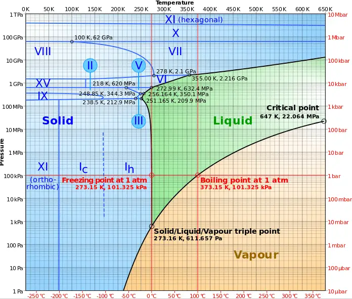
In general, condensation is the change of the physical state of matter from gas phase into liquid phase, and is the reverse of vaporisation. Flow processes associated with condensation on a solid surface are almost a mirror image of those involved in boiling. Condensation occurs when the temperature of a vapor is reduced below its saturation temperature or when the pressure of a vapor is increased above its saturation parameters (see phase diagram of water).
 By definition, multiphase flow is the interactive flow of two or more distinct phases with common interfaces in, say, a conduit. Each phase, representing a volume fraction (or mass fraction) of solid, liquid or gaseous matter, has its own properties, velocity, and temperature.
A multiphase flow can be simultaneous flow of:
- Materials with different states or phases (e.g. water-steam mixture).
- Materials with different chemical properties but in the same state or phase (e.g. oil droplets in water).
There are many combinations in industrial processes, but the most common being the simultaneous flow of steam and liquid water (as encountered in steam generators and condensers). In reactor engineering a great deal of study has been performed on the nature of two-phase flow in case of a loss-of-coolant accident (LOCA), which is an accident of importance in reactor safety and in all thermal-hydraulic analyses (DNBR analyses).
Characteristics of Two-phase Fluid Flow
All two-phase flow problems have features which are characteristically different from those found in single-phase problems.
- In the case of steam and liquid water the density of the two phases differs by a factor of about 1000. Therefore the influence of gravitational body force on multiphase flows is of much greater importance than in the case of single-phase flows.
- The sound speed changes dramatically for materials undergoing phase change, and can be orders of magnitude different. This significantly influences a flow through an orifice.
- The relative concentration of different phases is usually a dependent parameter of great importance in multiphase flows, while it is a parameter of no consequence in single-phase flows.
- The change of phase means flow-induced pressure drops can cause further phase-change (e.g. water can evaporate through an orifice) increasing the relative volume of the gaseous, compressible medium and increasing efflux velocities, unlike single-phase incompressible flow where decreasing of an orifice would decrease efflux velocities.
- The spatial distribution of the various phases in the flow channel strongly affects the flow behavior.
- There are many types of instabilities in multiphase flow.
 For condensation, latent heat effects associated with the phase change are significant, similarly as for boiling, but in reverse. Note that the enthalpy of condensation (or heat of condensation) is by definition equal to the enthalpy of vaporization with the opposite sign. Latent heat is the amount of heat added to or removed from a substance to produce a change in phase. During vaporisation, this energy breaks down the intermolecular attractive forces, and also must provide the energy necessary to expand the gas (the pΔV work). When latent heat is added or removed, no temperature change occurs. The enthalpy of vaporization is a function of the pressure at which that transformation takes place.
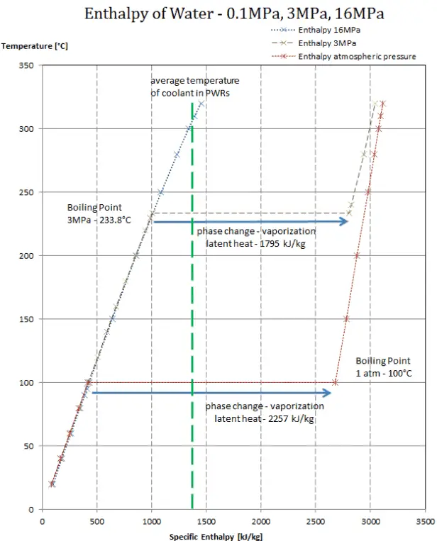
Latent heat of condensation – water at 0.1 MPa (atmospheric pressure)
hlg = – 2257 kJ/kg
Latent heat of condensation – water at 3 MPa
hlg = – 1795 kJ/kg
Latent heat of condensation – water at 16 MPa (pressure inside a pressurizer)
hlg = – 931 kJ/kg
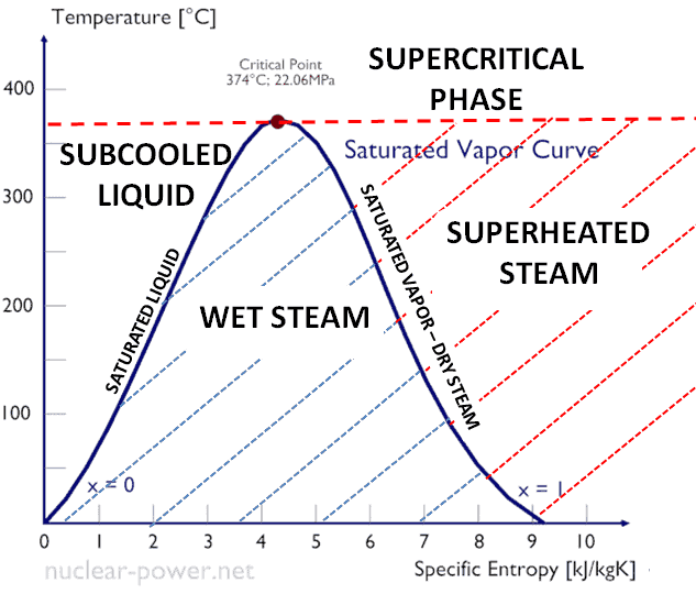
The heat of condensation diminishes with increasing pressure, while the boiling point increases. It vanishes completely at a certain point called the critical point. Above the critical point, the liquid and vapor phases are indistinguishable, and the substance is called a supercritical fluid.
The change from the liquid to the vapor state due to boiling is sustained by heat transfer from the solid surface; conversely, condensation of a vapor to the liquid state results in heat transfer to the solid surface. Boiling and condensation differ from other forms of convection in that they depend on the latent heat of vaporization, which is very high for common pressures, therefore large amounts of heat can be transferred during boiling and condensation essentially at constant temperature. Heat transfer coefficients, h, associated with boiling and condensation are typically much higher than those encountered in other forms of convection processes that involve a single phase.
Condensation Modes – Types of Condensation
From a practical engineering point of view condensation can be categorized according to several criteria.
In general, three distinct forms of condensation are observed:
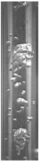
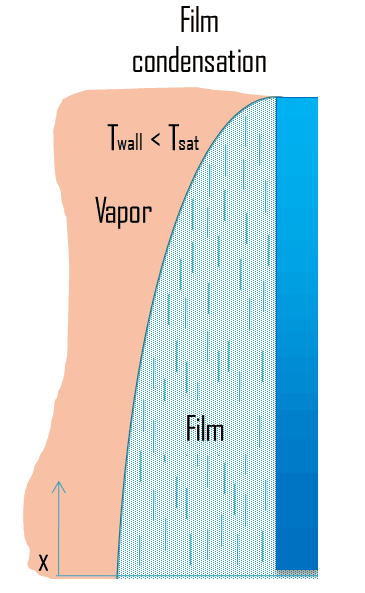
- Film condensation. In film condensation, the condensate wets the surface and forms a liquid film on the surface that slides down under the influence of gravity. Film condensation results in low heat transfer rates as the film of condensate impedes the heat transfer. The thickness of the film formed depends on many parameters including orientation of the surface, viscosity, rate of condensation etc. The film increases a thermal resistance to heat flow between the surface and the vapour. The rate of heat transfer is reduced because of this resistance.
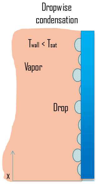
- Dropwise condensation. In dropwise condensation, the condensed vapor forms droplets on the surface instead of a continuous film. Dropwise condensation can occur when the surface is nonwetting or these droplets are taken away from the surface by external flow or by gravity. The vapour is in direct contact with the surface over most of the area and heat transfer rates are much higher (more than 3 – 10 times higher) as there is very little resistance for heat flow between the vapour and the surface. The droplets develop at nucleation sites (points of surface imperfections such as pit, scratch and cavities), and grow in size as more vapour condenses on its exposed surface. For steam condensers, it is common practice to use surface coatings (silicons, teflons or waxes) that inhibit wetting, and hence stimulate dropwise condensation. But coatings gradually lose their effectiveness due to removal, oxidation etc. In practice no surface is found to continue as nonwetting over any length of time. Since in most engineering applications it is often difficult to maintain this condition, using the value of heat transfer coefficients assuming dropwise condensation for design purposes is not advisable.
- Direct contact condensation. Direct contact condensation, DCC, occurs when vapor is brought into contact with a cold liquid. As in jet condensers, the cooling water is sprayed on the exhaust steam and there is direct contact between the exhaust steam and cooling water. The process of condensation is very fast and efficient, but here cooling water and condensed steam are mixed up. The advantages of direct contact condensation over the conventional processes using metallic transfer surfaces are due to the relative simplicity of design, less corrosion and scaling problems, lower maintenance costs, higher specific transfer areas, and higher transfer rates. Despite these advantages jet condensers are not usual in thermal power plants especially due to the loss of condensate.
___________
___________

Condensation in Power Plants – Main Condensator
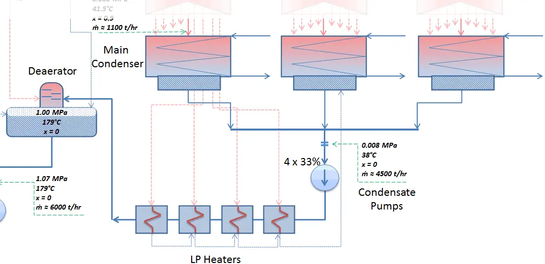 The main steam condenser (MC) system is designed to condense and deaerate the exhaust steam from the main turbine and provide a heat sink for the turbine bypass system. The exhausted steam from the LP turbines is condensed by passing over tubes containing water from the cooling system. There is a main condenser unit under each LP turbine, usually below the turbine with its axis perpendicular to the turbine axis. Since nuclear power plants usually contain also an auxiliary condenser (e.g. to condense steam from steam driven feedwater pumps), engineers use the term “main condenser“.
See also: Main Condenser
The condenser must maintain a sufficient low vacuum in order to increase the power plant efficiency. The vacuum pumps maintain a sufficient vacuum in the condenser by extracting air and uncondensed gases. The lowest feasible condenser pressure is the saturation pressure corresponding to the ambient temperature (e.g. absolute pressure of 0.008 MPa, which corresponds to 41.5°C). Note that, there is always a temperature difference between (around ΔT = 14°C) the condenser temperature and the ambient temperature, which originates from finite size and efficiency of condensers. Since neither the condenser is 100% efficient heat exchanger, there is always a temperature difference between the saturation temperature (secondary side) and the temperature of the coolant in the cooling system. Moreover, there is a design inefficiciency, which decreases the overall efficiency of the turbine. Ideally the steam exhausted into the condenser would have no subcooling. But real condensers are designed to subcool the liquid by a few degrees of Celsius in order to avoid the suction cavitation in the condensate pumps.
The steam condensers are broadly classified into two types:
- Surface condensers (or non-mixing type condensers). In surface condensers, there is no direct contact between the exhaust steam and the cooling water.
- Jet condensers (or mixing type condensers). In jet condensers there is direct contact between the exhaust steam and cooling water.
Condensation in Pressurizer
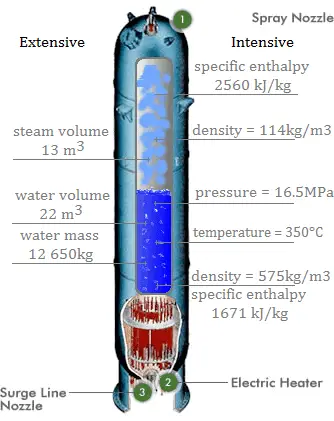
A pressurizer is a component of a pressurized water reactor. Pressure in the primary circuit of PWRs is maintained by a pressurizer, a separate vessel that is connected to the primary circuit (hot leg) and partially filled with water which is heated to the saturation temperature (boiling point) for the desired pressure by submerged electrical heaters. Temperature in the pressurizer can be maintained at 350 °C (662 °F), which gives a subcooling margin (the difference between the pressurizer temperature and the highest temperature in the reactor core) of 30 °C. Subcooling margin is very important safety parameter of PWRs, since the boiling in the reactor core must be excluded. The basic design of the pressurized water reactor includes such requirement that the coolant (water) in the reactor coolant system must not boil. To achieve this, the coolant in the reactor coolant system is maintained at a pressure sufficiently high that boiling does not occur at the coolant temperatures experienced while the plant is operating or in an analyzed transient.
Functions
Pressure in the pressurizer is controlled by varying the temperature of the coolant in the pressurizer. For these purposes two systems are installed. Water spray system and electrical heaters system. Volume of the pressurizer (tens of cubic meters) is filled with water on saturation parameters and steam. The water spray system (relatively cool water – from cold leg) can decrease the pressure in the vessel by condensing the steam on water droplets sprayed in the vessel. Since vapor is brought into contact with a cold liquid, in this case, we are talking about direct contact condensation. On the other hand the submerged electrical heaters are designed to increase the pressure by evaporation the water in the vessel. Water pressure in a closed system tracks water temperature directly; as the temperature goes up, pressure goes up.
Condensation in Containment Building
In case of Design Basis Accidents such as the Large Break Loss of Coolant Accident (LBLOCA) the pressure increase is usually significant and active containment systems (pressure-suppression systems) must be available in order to maintain the integrity (to keep the pressure and temperature under certain limits) of the containment building.
Pressure-suppression systems are critical to safety and greatly affect the size of containment. Suppression refers to condensing the steamafter a major break has released it from the cooling system. There are many designs of suppression systems around the world.
Most of Pressurized Water Reactors (PWRs) containments use two stage pressure-suppression systems:
- Fan Cooler System. This system circulates air through heat exchangers and filters to provide the cooling of containment atmosphere. Since this system is not sufficient for suppression during severe loss of coolant accidents, the containment spray system must be available as the secondary active pressure-suppression system.
- Containment Spray System. This system consist usually from three elements:
- Spray System Pump
- Spray System Tank
- Spray System Rings and Nozzles
When pressure increase inside the containment is indicated, thecontainment spray system is automatically started and the pumps (usually with 3×100% redundancy) take a suction from the tank (refueling water storage tank can be also used) and pump the water into spray nozzles located in the upper part of the containment. The water droplets, being cooler than the steam, will remove heat from the steam, which will cause the steam to condense. This will cause a reduction in the pressure of the building and will also reduce the temperature of the containment atmosphere. The spray system usually contains extra chemical additives dissolved in the tank to enhance the removal of particular radionuclides from the containment atmosphere. Especially radioiodine, which is of particular importance, can be effectively bonded to potassium hydroxide or sodium hydroxide.
Most of Boiling Water Reactors (BWR) containments use pressure-suppression pools in order to maintain the integrity of the containment building. The major containment designs are the Mark I, Mark II and the Mark III. The Mark I and Mark II containments consist of two main parts:
- Drywell. A drywell houses the reactor coolant system.
- Wetwell. A wetwell is a suppression chamber, which stores a large body of water and therefore it is commonly called as the suppression pool.
Water spray systems are usually installed in both the drywell and the wetwell. The Mark III design consists of a primary containment and a drywell.
Containment buildings and containment pressure-suppression systems vary widely depending on certain reactor design. In some cases really unique technologies can be installed. For example, the containment building of Loviisa NPP uses two ice condensers as the pressure-suppression system.
We hope, this article, Condensation – Heat Transfer, helps you. If so, give us a like in the sidebar. Main purpose of this website is to help the public to learn some interesting and important information about thermal engineering.