From Turbine Valves to Condenser – Expansion
These main steam lines are cross-tied (e.g. via steam collector pipe) near the turbine to ensure that the pressure difference between any of the steam generators does not exceed specific value thus maintaining system balance and ensuring uniform heat removal from the Reactor Coolant System (RCS). The steam flows through the main steam line isolation valves (MSIVs), which are very important from safety point of view, to the high pressure turbine. Directly at the inlet of the steam turbine, there are throttle-stop valves and control valves. Turbine control is achieved by varying these turbine valves openings. In the event of a turbine trip, the steam supply must be isolated very quickly, usually in the fraction of a second, so the stop valves must operate quickly and reliably.
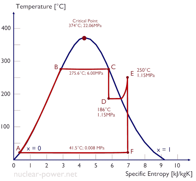
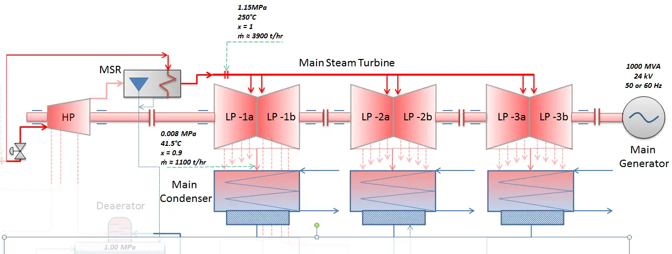
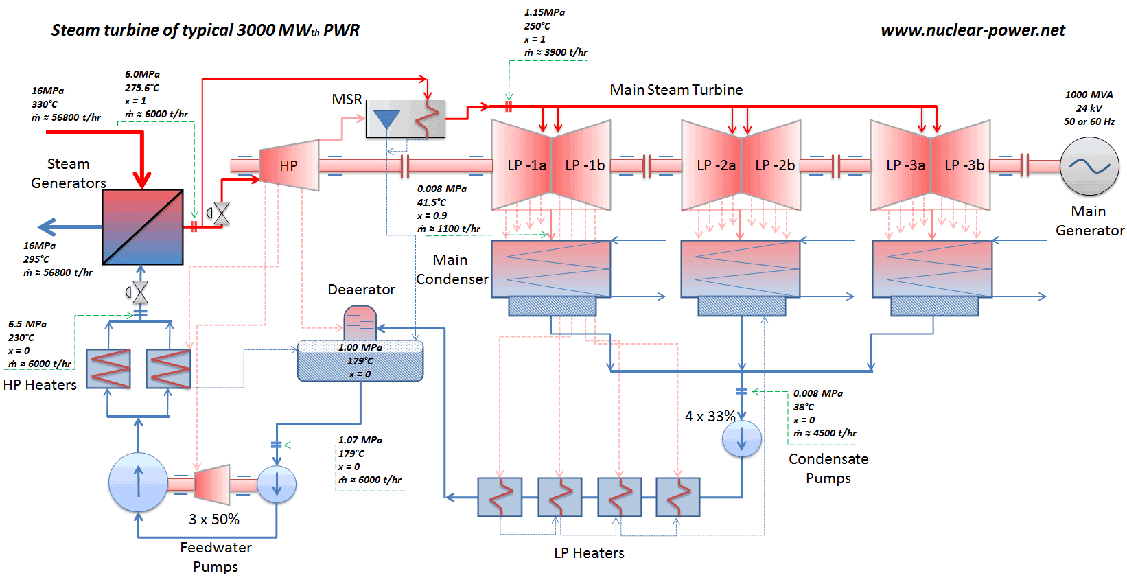
Typically most of nuclear power plants operates multi-stage condensing steam turbines. In these turbines the high-pressure stage receives steam (this steam is nearly saturated steam – x = 0.995 – point C at the figure; 6 MPa; 275.6°C) from a steam generator and exhaust it to moisture separator-reheater (MSR – point D). The steam must be reheated in order to avoid damages that could be caused to blades of steam turbine by low quality steam. High content of water droplets can cause the rapid impingement and erosion of the blades which occurs when condensed water is blasted onto the blades. To prevent this, condensate drains are installed in the steam piping leading to the turbine. The moisture-free steam is superheated by extraction steam from the high-pressure stage of turbine and by steam directly from the main steam lines.
The heating steam is condensed in the tubes and is drained to the feedwater system. The reheater heats the steam (point D) and then the steam is directed to the low-pressure stage of steam turbine, where expands (point E to F). The exhausted steam then condenses in the condenser and it is at a pressure well below atmospheric (absolute pressure of 0.008 MPa), and is in a partially condensed state (point F), typically of a quality near 90%. High pressure and low pressure stages of the turbine are usually on the same shaft to drive a common generator, but they have separate cases. The main generator produces electrical power, which is supplied to the electrical grid.
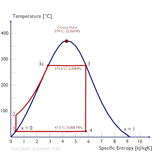
Isentropic expansion (expansion in a steam turbine) – Steam from the boiler expands adiabatically from state 3 to state 4 in a steam turbine to produce work and then is discharged to the condenser (partially condensed). The steam does work on the surroundings (blades of the turbine) and loses an amount of enthalpy equal to the work that leaves the system. The work done by turbine is given by WT = H4 – H3. Again the entropy remains unchanged.
We hope, this article, From Turbine Valves to Condenser – Expansion, helps you. If so, give us a like in the sidebar. Main purpose of this website is to help the public to learn some interesting and important information about thermal engineering.