Heat Flux Density – Thermal Flux
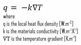
The rate of heat transfer per unit area normal to the direction of heat transfer is called heat flux. Sometimes it is also referred to as heat flux density. In SI its units are watts per square metre (W.m−2). It has both a direction and a magnitude, and so it is a vector quantity. The average heat flux is expressed as:
where A is the heat transfer area. The unit of heat flux in English units is Btu/h·ft2. Note that heat flux may vary with time as well as position on a surface.
In nuclear reactors, limitations of the local heat flux is of the highest importance for reactor safety. Since nuclear fuel consist of fuel rods, the heat flux is there defined in units of W/cm (local linear heat flux) or kW/rod (power per fuel rod).
Heat Flux Measurement
The measurement of heat flux can be performed in a few different manners.
- Measurement based on the temperature difference. A commonly known, but often impractical, method is performed by measuring a temperature difference over a piece of material with known thermal conductivity. This method assumes that the material’s thermal conductivity is well known. This method is analogous to a standard way to measure an electric current, where one measures the voltage drop over a known resistor.
- Measurement based on the use of the heat flux sensor. Heat flux can be directly measured via heat flux sensors or heat flux transducers. The most common type of heat flux sensor is a differential temperature thermopile which operates on essentially the same principal as the first measurement method. A heat flux sensor should measure the local heat flux density in one direction. The result is expressed in watts per square meter. This measurement has the advantage in that the thermal conductivity does not need to be a known parameter.
Example – Heat flux through a window
 Heat loss through windows
A major source of heat loss from a house is through the windows. Calculate the rate of heat flux through a glass window 1.5 m x 1.0 m in area and 3.0 mm thick, if the temperatures at the inner and outer surfaces are 14.0°C and 13.0°C, respectively. Calculate the heat flux through this window.
Solution:
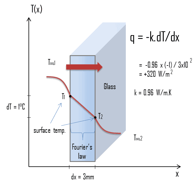
At this point, we know the temperatures at the surfaces of material. These temperatures are given also by conditions inside the house and outside the house. In this case, heat flows by conduction through the glass from the higher inside temperature to the lower outside temperature. We use the heat conduction equation:
We assume that the thermal conductivity of a common glass is k = 0.96 W/m.K.
The heat flux will then be:
q = 0.96 [W/m.K] x 1 [K] / 3.0 x 10⁻³ [m] = 320 W/m2
The total heat loss through this window will be:
qloss = q . A = 320 x 1.5 x 1.0 = 480W
Critical Heat Flux
 As was written, in nuclear reactors, limitations of the local heat flux is of the highest importance for reactor safety. For pressurized water reactors and also for boiling water reactors, there are thermal-hydraulic phenomena, which cause a sudden decrease in the efficiency of heat transfer (more precisely in the heat transfer coefficient). These phenomena occur at certain value of heat flux, known as the “critical heat flux”. The phenomena, that cause the deterioration of heat transfer are different for PWRs and for BWRs.
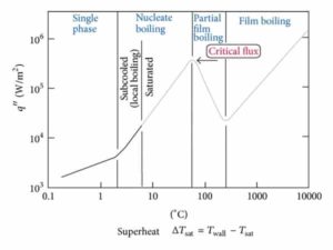
In both types of reactors, the problem is more or less associated with departure from nucleate boiling. The nucleate boiling heat flux cannot be increased indefinitely. At some value, we call it the “critical heat flux” (CHF), the steam produced can form an insulating layer over the surface, which in turn deteriorates the heat transfer coefficient. Immediately after the critical heat flux has been reached, boiling become unstable and film boiling occurs. The transition from nucleate boiling to film boiling is known as the “boiling crisis”. As was written, the phenomena, that cause the deterioration of heat transfer are different for PWRs and for BWRs.
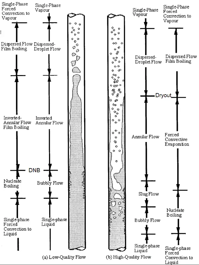
- Dryout. In BWRs, this phenomenon is known as the “dryout” and it is directly associated with changes in flow pattern during evaporation in the high-quality region. At given combinations of flow rate through a channel, pressure, flow quality, and linear heat rate, the wall liquid film may exhaust and the wall may be dried out. At normal, the fuel surface is effectively cooled by boiling coolant. However when the heat flux exceeds a critical value (CHF – critical heat flux) the flow pattern may reach the dryout conditions (thin film of liquid disappears). The heat transfer from the fuel surface into the coolant is deteriorated, with the result of a drastically increased fuel surface temperature. In the high-quality region, the crisis occurs at a lower heat flux. Since the flow velocity in the vapor core is high, post-CHF heat transfer is much better than for low-quality critical flux (i.e. for PWRs temperature rises are higher and more rapid).
-
If the heat flux of a boiling system is higher than the critical heat flux then DNB (Departure from Nucleate Boiling) may occur. Departure from Nucleate Boiling. In case of PWRs, the critical safety issue is named DNB (departure from nucleate boiling), which causes the formation of a local vapor layer, causing a dramatic reduction in heat transfer capability. This phenomenon occurs in the subcooled or low-quality region. The behaviour of the boiling crisis depends on many flow conditions (pressure, temperature, flow rate), but the boiling crisis occurs at a relatively high heat fluxes and appears to be associated with the cloud of bubbles, adjacent to the surface. These bubbles or film of vapor reduces the amount of incoming water. Since this phenomenon deteriorates the heat transfer coefficient and the heat flux remains, heat then accumulates in the fuel rod causing dramatic rise of cladding and fuel temperature. Simply, a very high temperature difference is required to transfer the critical heat flux being produced from the surface of the fuel rod to the reactor coolant (through vapor layer). In case of PWRs, the critical flow is inverted annular flow, while in BWRs, the critical flow is usually annular flow. The difference in flow regime between post-dryout flow and post-DNB flow is depicted in the figure. In PWRs at normal operation the flow is considered to be single-phase. But a great deal of study has been performed on the nature of two-phase flow in case of transients and accidents (such as the loss-of-coolant accident – LOCA or trip of RCPs), which are of importance in reactor safety and in must be proved and declared in the Safety Analysis Report (SAR).

We hope, this article, Heat Flux Density – Thermal Flux, helps you. If so, give us a like in the sidebar. Main purpose of this website is to help the public to learn some interesting and important information about thermal engineering.