Pressure Drop – Fuel Assembly
In general, total fuel assembly pressure drop is formed by fuel bundle frictional drop (dependent on relative roughness of fuel rods, reynolds number, hydraulic diameter etc.) and other pressure drops of structural elements (top and bottom nozzle, spacing grids or mixing grids).
See also: Fluid Acceleration – Pressure Loss
In general, it is not so simple to calculate pressure drops in fuel assemblies (especially the spacing grids) and it belongs to key know-how of certain fuel manufacturer. Mostly, pressure drops are measured in experimental hydraulic loops, rather than calculated.
Engineers use the pressure loss coefficient, PLC. It is noted K or ξ (pronounced “xi”). This coefficient characterizes pressure loss of a certain hydraulic system or of a part of a hydraulic system. It can be easily measured in hydraulic loops. The pressure loss coefficient can be defined or measured for both straight pipes and especially for local (minor) losses.
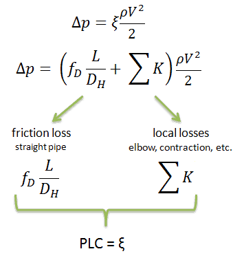
Using data from below mentioned example, the pressure loss coefficient (only frictional from straight pipe) is equal to ξ = fDL/DH = 4.9. But the overall pressure loss coefficient (including spacing grids, top and bottom nozzles etc.) is usually about three times higher. This PLC (ξ = 4.9) causes that the pressure drop is of the order of (using the previous inputs) Δpfriction = 4.9 x 714 x 52/ 2 = 43.7 kPa (without spacing grids, top and bottom nozzles). About three times higher real PLC means about three times higher Δpfuel will be.
The overall reactor pressure loss, Δpreactor, must include:
- downcomer and reactor bottom
- lower support plate
- fuel assembly including spacing grids, top and bottom nozzles and other structural components – Δpfuel
- upper guide structure assembly
In result the overall reactor pressure loss – Δpreactor is usually of the order of hundreds kPa (let say 300 – 400 kPa) for design parameters.
It is an illustrative example, previous data do not correspond to any reactor design.
Example: Frictional Pressure Loss – Fuel Bundle
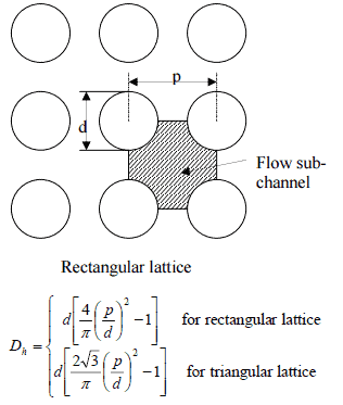 Calculate the frictional pressure loss of a single fuel rod inside a reactor core at normal operation (design flow rate). Assume that this fuel rod is part of a fuel bundle with the rectangular fuel lattice and this fuel bundle does not contain spacing grids. Its height is h = 4m and the core flow velocity is constant and equal to Vcore = 5 m/s.
Assume that:
- the outer diameter of the cladding is: d = 2 x rZr,1 = 9,3 mm
- the pitch of fuel pins is: p = 13 mm
- the relative roughness is ε/D = 5×10⁻⁴
- the fluid density is: ρ = 714 kg/m3
- the core flow velocity is constant and equal to Vcore = 5 m/s
- the average temperature of reactor coolant is: Tbulk = 296°C
Calculation of the Reynolds number
To calculate the Reynolds number, we have to know:
- the outer diameter of the cladding is: d = 2 x rZr,1 = 9,3 mm (to calculate the hydraulic diameter)
- the pitch of fuel pins is: p = 13 mm (to calculate the hydraulic diameter)
- the dynamic viscosity of saturated water at 300°C is: μ = 0.0000859 N.s/m2
- the fluid density is: ρ = 714 kg/m3
The hydraulic diameter, Dh, is a commonly used term when handling flow in non-circular tubes and channels. The hydraulic diameter of the fuel channel, Dh, is equal to 13,85 mm.
See also: Hydraulic Diameter
The Reynolds number inside the fuel channel is then equal to:
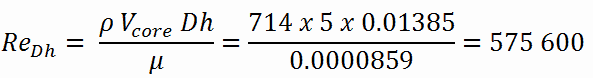
This fully satisfies the turbulent conditions.
Calculation of the Darcy Friction Factor
The friction factor for turbulent flow depends strongly on the relative roughness. It is determined by the Colebrook equation or can be determined using the Moody chart. The Moody chart for Re = 575 600 and ε/D = 5 x 10⁻⁴ returns following values:
- the Darcy friction factor is equal to fD = 0.017
- the Fanning friction factor is equal to fF = fD/4 = 0.00425
Therefore, the pressure loss coefficient (only frictional from straight pipe) is equal to ξ = fDL/DH = 4.9.
We hope, this article, Pressure Drop – Fuel Assembly, helps you. If so, give us a like in the sidebar. Main purpose of this website is to help the public to learn some interesting and important information about thermal engineering.