Reynolds Number Regimes
Laminar flow. For practical purposes, if the Reynolds number is less than 2000, the flow is laminar. The accepted transition Reynolds number for flow in a circular pipe is Red,crit = 2300.
Transitional flow. At Reynolds numbers between about 2000 and 4000 the flow is unstable as a result of the onset of turbulence. These flows are sometimes referred to as transitional flows.
Turbulent flow. If the Reynolds number is greater than 3500, the flow is turbulent. Most fluid systems in nuclear facilities operate with turbulent flow.
Definition of Reynolds Number
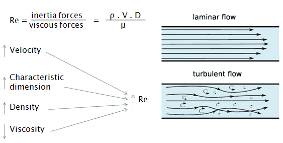
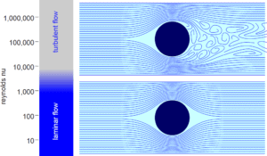
The Reynolds number is the ratio of inertial forces to viscous forces and is a convenient parameter for predicting if a flow condition will be laminar or turbulent. It can be interpreted that when the viscous forces are dominant (slow flow, low Re) they are sufficient enough to keep all the fluid particles in line, then the flow is laminar. Even very low Re indicates viscous creeping motion, where inertia effects are negligible. When the inertial forces dominate over the viscous forces (when the fluid is flowing faster and Re is larger) then the flow is turbulent.
It is a dimensionless number comprised of the physical characteristics of the flow. An increasing Reynolds number indicates an increasing turbulence of flow.
where:
V is the flow velocity,
D is a characteristic linear dimension, (travelled length of the fluid; hydraulic diameter etc.)
ρ fluid density (kg/m3),
μ dynamic viscosity (Pa.s),
ν kinematic viscosity (m2/s); ν = μ / ρ.
Laminar vs. Turbulent Flow
Laminar flow:
- Re < 2000
- ‘low’ velocity
- Fluid particles move in straight lines
- Layers of water flow over one another at different speeds with virtually no mixing between layers.
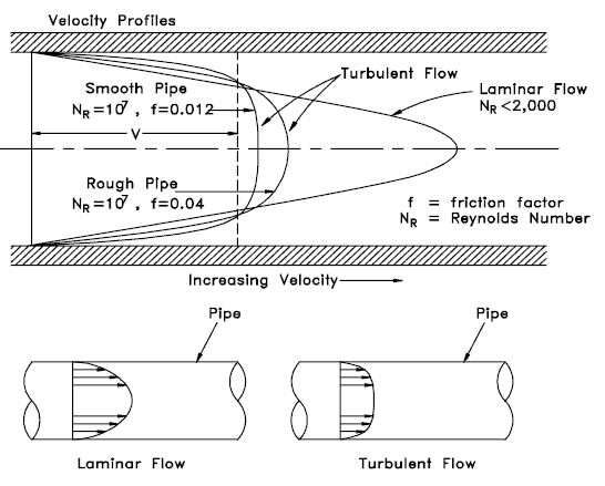
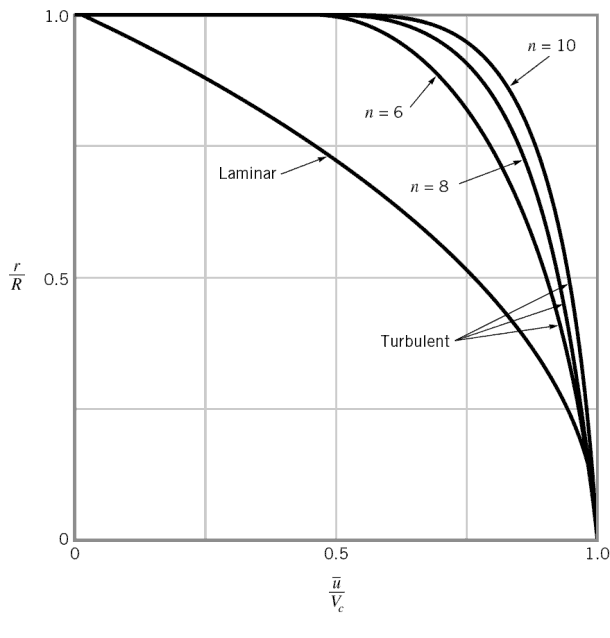
- The flow velocity profile for laminar flow in circular pipes is parabolic in shape, with a maximum flow in the center of the pipe and a minimum flow at the pipe walls.
- The average flow velocity is approximately one half of the maximum velocity.
- Simple mathematical analysis is possible.
- Rare in practice in water systems.
Turbulent Flow:
- Re > 4000
- ‘high’ velocity
- The flow is characterized by the irregular movement of particles of the fluid.
- Average motion is in the direction of the flow
- The flow velocity profile for turbulent flow is fairly flat across the center section of a pipe and drops rapidly extremely close to the walls.
- The average flow velocity is approximately equal to the velocity at the center of the pipe.
- Mathematical analysis is very difficult.
- Most common type of flow.
Reynolds Number and Pipe Flow
The internal flow (e.g. flow in a pipe) configuration is a convenient geometry for heating and cooling fluids used in energy conversion technologies such as nuclear power plants.
In general, this flow regime is of importance in engineering, because circular pipes can withstand high pressures and hence are used to convey liquids. Non-circular ducts are used to transport low-pressure gases, such as air in cooling and heating systems.
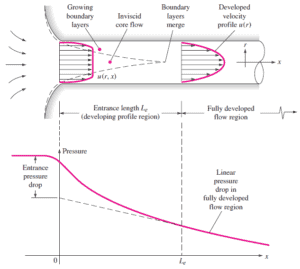
For internal flow regime an entrance region is typical. In this region a nearly inviscid upstream flow converges and enters the tube. To characterize this region the hydrodynamic entrance length is introduced and is approximately equal to:
The maximum hydrodynamic entrance length, at ReD,crit = 2300 (laminar flow), is Le = 138d, where D is the diameter of the pipe. This is the longest development length possible. In turbulent flow, the boundary layers grow faster, and Le is relatively shorter. For any given problem, Le / D has to be checked to see if Le is negligible when compared to the pipe length. At a finite distance from the entrance, the entrance effects may be neglected, because the boundary layers merge and the inviscid core disappears. The tube flow is then fully developed.
Hydraulic Diameter
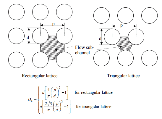
Since the characteristic dimension of a circular pipe is an ordinary diameter D and especially reactors contains non-circular channels, the characteristic dimension must be generalized.
For these purposes the Reynolds number is defined as:
where Dh is the hydraulic diameter:
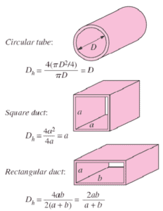 The hydraulic diameter, Dh, is a commonly used term when handling flow in non-circular tubes and channels. The hydraulic diameter transforms non-circular ducts into pipes of equivalent diameter. Using this term, one can calculate many things in the same way as for a round tube. In this equation A is the cross-sectional area, and P is the wetted perimeter of the cross-section. The wetted perimeter for a channel is the total perimeter of all channel walls that are in contact with the flow.
We hope, this article, Reynolds Number for Pipe Flow, helps you. If so, give us a like in the sidebar. Main purpose of this website is to help the public to learn some interesting and important information about thermal engineering.
