Facebook Instagram Youtube Twitter

Thermal efficiency of combined heat and power systems

Learn about thermal efficiency in Combined Heat and Power (CHP) systems, highlighting the calculation, factors influencing it, and its advantages.

Thermal efficiency of combined heat and power systems

Understanding Thermal Efficiency in Combined Heat and Power Systems

Combined Heat and Power (CHP), also known as cogeneration, is a highly efficient process that generates electricity and captures usable heat simultaneously. This approach is far more efficient than conventional methods of generating electricity and providing heat separately. The thermal efficiency of CHP systems is a crucial metric that signifies the effectiveness of energy utilization in this process.

What is Thermal Efficiency?

Thermal efficiency in the context of CHP systems refers to the ratio of useful energy output (both electrical and thermal) to the energy input, usually measured using fuels like natural gas or coal. The higher the thermal efficiency, the more effectively a system converts fuel into usable energy, thereby reducing waste and operating costs.

Calculation of Thermal Efficiency

The thermal efficiency (\(\eta\)) of CHP systems can be calculated using the equation:

\[ \eta = \frac{{\text{Useful heat output (Q_h) + Useful electrical output (W_e)}}}{{\text{Total fuel energy input (Q_f)}}} \times 100\% \]

Where:

  • \(Q_h\) is the thermal energy produced by the system.
  • \(W_e\) is the electrical energy generated.
  • \(Q_f\) is the energy content of the fuel consumed.

Factors Influencing Thermal Efficiency of CHP Systems

The thermal efficiency of CHP systems is influenced by several factors, including:

  • Type of fuel used: Different fuels have varying energy densities and efficiencies. Natural gas, for example, is often preferred for its higher efficiency and cleaner combustion compared to coal.
  • System design: The design of the CHP system, including the technology used for both the generation of electricity and the capture of heat, significantly affects efficiency.
  • Operating conditions: Operating the system within its optimal range of conditions, such as temperature and pressure, ensures maximum efficiency.
  • Maintenance: Regular maintenance helps prevent the degradation of system components, which can impede efficient operation over time.

Advantages of High Thermal Efficiency in CHP Systems

Beyond the basic benefit of reduced fuel consumption, high thermal efficiency in CHP systems offers multiple advantages:

  • Cost Savings: Efficient energy use translates to lower operating costs by decreasing the amount of fuel required per unit of output.
  • Environmental Benefits: By maximizing the energy extracted from fuel, CHP systems lower greenhouse gas emissions and reduce the environmental footprint.
  • Energy Security: Enhancing efficiency contributes to energy security by making better use of domestic fuel resources and reducing dependence on foreign energy supplies.
  • Reliability: CHP systems can provide more reliable energy supply, particularly in areas susceptible to power outages, as they can be operated independently of the power grid.

In conclusion, the thermal efficiency of combined heat and power systems is a critical measure that not only reflects operational effectiveness but also impacts economic and environmental outcomes. By understanding and optimizing this efficiency, we can better harness the benefits of CHP technology, making it a cornerstone in the pursuit of sustainable energy solutions.

Understanding Heat Flux in Thermal Analysis

Heat flux is the rate of thermal energy transfer through a surface per unit area, measured in watts per square meter.

Understanding Heat Flux in Thermal Analysis

Understanding Heat Flux in Thermal Analysis

Heat flux is a fundamental concept in thermal analysis, pivotal in understanding how heat transfers in materials and systems across engineering and scientific disciplines. It is especially crucial in disciplines such as mechanical, aerospace, and civil engineering where thermal management is essential to system stability and safety. This article aims to explain what heat flux is, how it can be calculated, and its importance in various applications.

What is Heat Flux?

Heat flux is a measure of the rate of heat energy transfer through a given surface per unit area. It is typically measured in watts per square meter (W/m2). The concept is crucial for the design and analysis of heating and cooling systems, insulation, and various other engineering applications where heat transfer needs to be controlled. Heat flux can occur through conduction, convection, or radiation, and each mode of transfer has its implications for how systems are designed.

Calculating Heat Flux

The basic calculation of heat flux (\(\Phi_q\)) for conduction through a solid material can be derived from Fourier’s Law of thermal conduction, which states that the heat transfer rate is proportional to the negative gradient of temperatures and the area through which the heat is flowing. Mathematically, it can be expressed as:

\[\Phi_q = -k * A * \frac{\Delta T}{\Delta x}\]

  • k – Thermal conductivity of the material (W/m°C).
  • A – Area through which heat is being transferred (m2).
  • ΔT – Temperature difference across the material (°C).
  • Δx – Thickness of the material (m).

For convective heat transfer, the heat flux can be calculated using Newton’s law of cooling:

\[\Phi_q = h * A * (T_s – T_\infty)\]

  • h – Convective heat transfer coefficient (W/m2°C).
  • Ts – Surface temperature (°C).
  • T∞ – Ambient temperature (°C).

In situations involving thermal radiation, the heat flux can be estimated using the Stefan-Boltzmann law:

\[\Phi_q = ε * σ * A * (T_s^4 – T_env^4)\]

  • ε – Emissivity of the surface.
  • σ – Stefan-Boltzmann constant (5.67 x 10⁻⁸ W/m2K4).
  • Ts and Tenv – Surface and environment temperatures respectively (K).

Applications of Heat Flux in Engineering

Understanding and controlling heat flux is critical in many engineering applications. For example:

  • Electronic Device Design: In microelectronics, engineers must ensure adequate heat dissipation to prevent overheating and failure of components.
  • Building Design: In architectural engineering, heat flux calculations help in designing building envelopes with effective thermal insulation, reducing energy costs.
  • Aerospace: Thermal management is crucial in aerospace to protect structures and instruments from extreme temperatures encountered during high-speed flight or space missions.

Heat flux sensors and calculations are also essential tools in experimental settings where researchers study heat transfer rates under various conditions to validate theoretical models or to better understand thermodynamic processes.

Conclusion

Heat flux is a key parameter in thermal analysis that helps engineers and scientists understand and optimize heat transfer in a wide range of applications. By accurately calculating and managing heat flux, better performance, safety, and efficiency can be achieved in products and systems across various industries.

In summary, whether you are engineering a new product, designing a building, or analyzing space shuttle components, understanding heat flux can provide insights that are crucial for thermal management and overall system success.

Principles of Cryogenic Heat Transfer

Learn about cryogenic heat transfer, the study of how heat moves at extremely low temperatures crucial for modern engineering and technology.

Principles of Cryogenic Heat Transfer

Understanding Cryogenic Heat Transfer

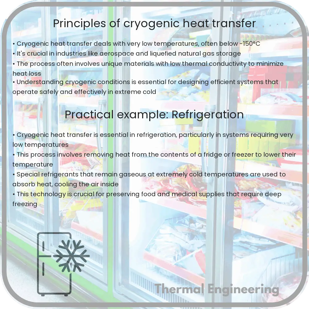
Cryogenic heat transfer is a fundamental aspect of engineering that deals with the behavior of materials and thermal energy at very low temperatures, typically below -150 degrees Celsius (-238 degrees Fahrenheit). This field is crucial in various applications such as in the preservation of biological materials, superconducting magnets, and space exploration. In this article, we will explore the basic principles of cryogenic heat transfer, focusing on conduction, convection, and radiation, which are key mechanisms through which heat is transferred in cryogenic environments.

Conduction in Cryogenics

Conduction is the transfer of heat through a solid medium without any physical movement of the material. In cryogenics, the conduction properties of materials significantly change as the temperature decreases. Generally, materials become better thermal conductors at lower temperatures. The rate of heat transfer by conduction can be described by Fourier’s law:

q = -k * A * (dT/dx)

  • q is the heat transfer per unit time,
  • k is the thermal conductivity of the material,
  • A is the cross-sectional area through which heat is being transferred,
  • dT/dx is the temperature gradient.

For example, materials like copper and silver, which are already good conductors at room temperature, exhibit even higher conductivities at cryogenic temperatures, making them ideal for applications like cooling systems in space technology.

Convection in Cryogenics

Convection involves the transfer of heat through a fluid (which can be a liquid or gas) that is caused by molecular motion when the fluid is heated. In cryogenic systems, convection can occur in cryogens like liquid nitrogen or helium. The effectiveness of convective heat transfer is influenced by the properties of the fluid, such as viscosity and thermal conductivity, which also change at low temperatures. The convective heat transfer can be expressed by Newton’s law of cooling:

q = h * A * (Ts – T∞)

  • q is the heat transfer per unit time,
  • h is the convective heat transfer coefficient,
  • A is the area through which heat is being transferred,
  • Ts is the surface temperature,
  • T∞ is the fluid temperature far from the surface.

The control of convection is critical in preventing the rapid vaporization of cryogenic fluids, which can lead to inefficiencies and safety risks in systems such as cryogenic fuel tanks.

Radiation in Cryogenics

Radiation is the transfer of heat in the form of electromagnetic waves and does not require a medium. This form of heat transfer becomes significant in cryogenic temperatures, especially in vacuum environments such as space. The Stefan-Boltzmann law, which describes this phenomenon, is given by:

q = ε * σ * A * (T4 – T∞4)

  • q is the heat transfer per unit time,
  • ε is the emissivity of the material,
  • σ is the Stefan-Boltzmann constant,
  • A is the area through which heat is being transferred,
  • T is the temperature of the radiating surface,
  • T∞ is the ambient temperature.

Materials used in cryogenic environments often have low emissivity to minimize radiative heat loss, which is critical in maintaining the integrity and efficiency of cryogenic systems.

Conclusion

Cryogenic heat transfer is an intricate field that plays a vital role in modern technology and scientific research. Understanding the principles of conduction, convection, and radiation at low temperatures helps engineers design more efficient and effective cryogenic systems. Whether it’s in medical storage systems, spacecraft, or superconducting devices, the principles of cryogenic heat transfer are fundamental to achieving desired outcomes in various high-tech fields.

As the application of cryogenic technologies expands, the understanding and manipulation of these heat transfer principles will continue to be a crucial aspect of innovation and development in cold-environment engineering.

How Does Solar Thermal Heating Work?

Learn about solar thermal heating, a green technology using the sun’s energy to heat water and buildings, and its components and applications.

How Does Solar Thermal Heating Work?

Understanding Solar Thermal Heating

Solar thermal heating is a technology that harnesses the sun’s energy to produce heat. This heat can then be used in various applications, from heating water and buildings to generating electricity. The principal components of a solar thermal system include the solar collector, heat transfer fluid, heat storage unit, and heat exchanger. Let’s break down how each component works and contributes to the overall system.

Solar Collectors

The core of a solar thermal system is the solar collector. This component is designed to capture and absorb solar radiation. There are several types of solar collectors, but the most common are flat-plate collectors and evacuated tube collectors. Flat-plate collectors consist of a dark, heat-absorbing surface, a series of tubes to carry the heat transfer fluid, and an insulating backing. Evacuated tube collectors, on the other hand, are made up of multiple glass tubes, each containing absorber plates within a vacuum which helps minimize heat loss.

Heat Transfer Fluid

The heat transfer fluid flows through the collector, absorbing the heat generated by the sun’s rays. This fluid can be water, antifreeze (typically a glycol mixture), or another type of fluid capable of heat absorption and retention. The choice of fluid depends on the system’s requirements and environmental factors like the likelihood of freezing temperatures.

Heat Storage Unit

Once the heat transfer fluid has absorbed heat from the collectors, it needs to either be used immediately or stored. A heat storage unit is integral for maintaining the system’s efficiency, allowing for the delayed use of the heat. Common storage solutions include water tanks or phase change materials that can store large amounts of heat with minimal physical changes in the storage media.

Heat Exchanger

In many solar thermal systems, a heat exchanger is a critical component. This device transfers the heat from the solar-heated fluid to water or air which is then used for domestic heating or hot water. In domestic hot water systems, for example, the heat exchanger warms water in an insulated tank that can be used throughout the home or building.

Applications of Solar Thermal Heating

  1. Domestic Water Heating: One of the most common uses of solar thermal technology is to provide hot water for household use. This application can significantly reduce energy bills and carbon footprints.
  2. Space Heating: Another application is in space heating, where solar thermal systems integrate with in-floor heating systems or radiators to warm living spaces.
  3. Industrial Processes: Industries that require a large amount of heat can use solar thermal systems to supplement or replace other energy sources, reducing operational costs and environmental impact.
  4. Power Generation: At a larger scale, solar thermal energy can be used to produce steam, driving turbines to generate electricity in a process known as concentrated solar power (CSP).

Benefits of Solar Thermal Heating

  • Sustainability: Solar thermal systems use the sun’s renewable energy, reducing reliance on fossil fuels and decreasing pollution and greenhouse gas emissions.
  • Cost-Effectiveness: After the initial setup costs, the operational expenses for solar thermal systems are significantly lower than conventional heating systems.
  • Low Maintenance: These systems require minimal maintenance, making them a hassle-free solution for long-term heating needs.

Solar thermal heating is a testament to how engineering can harness natural resources to provide sustainable, economically feasible solutions for both everyday and industrial applications. By understanding the basic principles and components involved, we can better appreciate the potential and real-world benefits of this green technology.

Understanding the Otto Cycle in Engines

Learn about the Otto Cycle, a key concept explaining the function of gasoline engines through four pivotal stages: intake, compression, combustion, and exhaust.

Understanding the Otto Cycle in Engines

Understanding the Otto Cycle in Engines

The Otto Cycle is a fundamental concept used to describe the functioning of typical gasoline internal combustion engines, named after Nikolaus Otto, who invented it in 1876. This thermodynamic cycle illustrates the idealized processes that such an engine undergoes to convert the energy stored in its fuel into mechanical work.

The Otto cycle consists of four primary stages:

  1. Intake Stroke: The cycle begins when the piston moves from the top to the bottom of the cylinder, drawing in a mixture of air and fuel into the combustion chamber through the intake valve.
  2. Compression Stroke: With the intake valve closed, the piston moves back up the cylinder, compressing the air-fuel mixture. This compression leads to an increase in the mixture’s temperature and pressure, preparing it for ignition.
  3. Combustion Stroke: At the top of the compression stroke, the spark plug ignites the compressed air-fuel mixture, causing a rapid combustion. The high pressure from this combustion forcefully pushes the piston back down the cylinder, generating the power output of the engine.
  4. Exhaust Stroke: Finally, as the piston moves back up again, it expels the spent gas from the combustion through the open exhaust valve, clearing the way for the next cycle.

These four strokes are represented in a pressure-volume (P-V) diagram, showing the changes in internal pressure and volume within the engine cylinder throughout the cycle. The ideal efficiency of the Otto cycle can be expressed by the equation:

\[ \text{Efficiency} = 1 – \left(\frac{V1}{V2}\right)^{\gamma-1} \]

Where \(V1\) and \(V2\) are the volumes at the beginning and end of the compression stroke, respectively, and \(\gamma\) (gamma) is the specific heat ratio of the gas.

Basics of Cryogenic Fluid Dynamics

Cryogenic fluid dynamics is a branch of fluid mechanics that deals with the behavior of very low temperature materials, typically below -150 degrees Celsius. These materials are often in liquid state, such as liquid nitrogen or liquid helium, and require special handling techniques due to their unique properties.

Key aspects and challenges in cryogenic fluid dynamics include:

  • Temperature Management: Maintaining the extremely low temperature necessary for cryogens is crucial, as any significant temperature increase can lead to rapid boiling and gas expansion.
  • Phase Change: Cryogenic fluids can change from liquid to gas at very low temperatures which can significantly affect flow and pressure dynamics within a system.
  • Insulation: Effective insulation is critical in cryogenic systems to prevent heat ingress from the surrounding environment.
  • Material Compatibility: Materials used in the construction of storage and transport mechanisms for cryogenic fluids must be compatible with low temperatures to avoid brittleness and cracking.

Understanding the flow characteristics of cryogenic fluids is essential for applications such as rocket propulsion systems, magnetic resonance imaging (MRI) systems, and large-scale superconducting devices. The study of these flows involves advanced thermodynamics and fluid mechanics principles, often requiring specialized simulation tools for accurate prediction and analysis.

Engineers and scientists working with cryogenic systems often employ the principles of compressible flow mechanics due to the rapid changes in density and other physical properties at low temperatures. Accurate measurements and control techniques are developed to handle the complexities of these substances, ensuring safety, efficiency, and functionality in their applications.

What Is a Thermal Barrier in Engineering?

Learn about thermal barriers in engineering, their types, functions, and importance in various industries for heat management and safety.

What Is a Thermal Barrier in Engineering?

What Is a Thermal Barrier in Engineering?

In engineering, a thermal barrier refers to a material layer or coating applied to surfaces or integrated within structures to reduce or prevent the transfer of heat. This concept is crucial in various applications, ranging from construction and aerospace to automotive industries, where managing heat flow can significantly influence safety, energy efficiency, and material longevity.

Types of Thermal Barriers

Thermal barriers typically come in different forms based on their application and the specific requirements of a project:

  • Thermal Barrier Coatings (TBCs): These are advanced materials usually applied to metal surfaces in thin layers. Commonly used in gas turbine engines, the coatings protect structural components from extreme temperatures, thereby enhancing their performance and durability.
  • Insulation Materials: Used in buildings and various mechanical systems, these materials, such as fiberglass, foam, or aerogels, trap air or other gases to reduce heat flow.
  • Reflective Barriers: Often used in buildings, reflective barriers work by reflecting radiant heat instead of absorbing it. Aluminum foil is a typical example, used in attic spaces to reflect heat away from a building.

Function and Importance of Thermal Barriers

Thermal barriers serve multiple functions in engineering:

  • Heat Resistance: They protect structural and mechanical components from overheating, thus preserving their integrity and functionality.
  • Energy Efficiency: By reducing unwanted heat transfer, thermal barriers help maintain desired temperatures with less energy, contributing to lower heating and cooling costs.
  • Safety: In automotive and aerospace industries, thermal barriers reduce the risk of fire and other heat-related hazards.

Application Examples

The application of thermal barriers is extensive and varies across different fields:

  • Construction: In residential and commercial buildings, insulation in walls, roofs, and floors helps maintain indoor climate control and reduces energy costs.
  • Aerospace: Thermal barrier coatings are critical in spacecraft, where they protect hulls from the extreme temperatures encountered during re-entry into the Earth’s atmosphere.
  • Automotive: Engines and exhaust systems often feature thermal barriers to manage heat and improve efficiency and safety.

In conclusion, thermal barriers play a critical role in engineering by managing heat transfer in various environments and applications. Their use helps in enhancing the performance, durability, and safety of technological systems, while also contributing to sustainability and energy conservation efforts.

How Do Dew Point Hygrometers Work?

Learn about dew point hygrometers, devices that measure the temperature at which air becomes fully saturated with moisture, used in meteorology, HVAC, and industrial processes.

How Do Dew Point Hygrometers Work?

Understanding Dew Point Hygrometers

Dew point hygrometers are critical instruments used in various fields such as meteorology, HVAC (heating, ventilation, and air conditioning), and industrial processes. These devices measure the dew point temperature, which is the temperature at which air becomes fully saturated with moisture and water vapor begins to condense into dew. Understanding how these devices work provides insight into atmospheric moisture, weather predictions, and maintaining controlled environments.

Principles of Dew Point Measurement

The basic principle behind a dew point hygrometer involves cooling a surface or a mirror until water vapor from the air starts to condense on it. The temperature at which condensation begins is the dew point temperature. This temperature is a direct measure of the amount of moisture in the air; the higher the dew point, the more moisture the air contains.

Types of Dew Point Hygrometers

There are several types of dew point hygrometers, each employing different methods to determine the dew point temperature:

  • Chilled Mirror Hygrometer: This is one of the most accurate types of dew point hygrometers. It involves a cooled mirror whose temperature is precisely controlled. Air passes over the mirror, and the temperature at which condensation is observed is detected using optical sensors. This method is highly accurate and is often used in laboratory settings.
  • Capacitive Hygrometer: These devices measure the dew point by detecting changes in capacitance caused by condensation affecting an electrically charged plate. These are commonly used in industrial applications due to their robustness and long-term stability.
  • Ceramic Hygrometer: Utilizing a porous ceramic material, these hygrometers sense changes in physical properties that occur as moisture is absorbed. The ceramic’s electrical properties change as it absorbs water, which can be measured and related to the air’s dew point.

Applications of Dew Point Hygrometers

Dew point hygrometers play a crucial role in numerous practical applications:

  • Meteorology: They are used to forecast weather by helping in understanding moisture content in the air, which is critical for predicting fog, dew, or rainfall.
  • HVAC Systems: Maintaining the right humidity levels is essential for human comfort as well as for the prevention of mold and mildew in buildings. Hygrometers help in regulating these systems efficiently.
  • Industrial Processes: Many manufacturing processes, such as in the pharmaceutical and textile industries, require strict humidity control for quality assurance. Dew point hygrometers ensure that these conditions are met.

Conclusion

Dew point hygrometers are indispensable tools in environments where moisture control is critical. By understanding and measuring the dew point temperature, they provide valuable data that helps in weather forecasting, improving indoor air quality, and ensuring optimal conditions in various industrial processes. With advancements in technology, the accuracy and efficiency of these instruments continue to improve, making them even more integral to modern scientific and industrial applications.

Thermal radiation in fire engineering

Explore the role of thermal radiation in fire engineering, highlighting its impact on fire spread, safety measures, and firefighting tactics.

Thermal radiation in fire engineering

Understanding Thermal Radiation in Fire Engineering

Thermal radiation plays a critical role in fire engineering, impacting how fires spread and how they are managed. This form of energy transfer involves the emission of infrared radiation from a hot body (such as a fire) which may affect surrounding materials and structures. Understanding thermal radiation is essential for developing fire safety measures, designing safer buildings, and improving fire fighting strategies.

Basics of Thermal Radiation

Thermal radiation is a type of heat transfer that does not require any medium. It is the process by which heat is directly emitted as electromagnetic waves, primarily in the infrared spectrum. The amount of thermal radiation emitted by a surface at a given temperature is described by the Stefan-Boltzmann Law:

E = σT4

Where:

  • E is the emissive power (the total radiation emitted per unit area).
  • σ (sigma) is the Stefan-Boltzmann constant, approximately 5.67 * 10-8 W/m2K4.
  • T is the absolute temperature in Kelvin.

As indicated by this equation, the emissive power of an object increases rapidly with an increase in temperature. This fundamental principle is central to fire engineering as it helps in estimating the various effects a fire can have in different scenarios.

Role of Thermal Radiation in Fire Spread

One of the key aspects of fire safety engineering is understanding and controlling the spread of fire within buildings and other structures. Thermal radiation can cause the ignition of combustible materials without direct contact with the fire source. This is known as radiant heat transfer, and its influence on fire spread is significant, particularly in environments where there are large, open spaces.

In fire safety engineering, it is important to factor in the contribution of thermal radiation when designing structures. The following aspects are generally considered:

  • The distance between potential fuel sources and the fire, as the intensity of radiation decreases with the square of the distance from the source.
  • The properties of the surfaces regarding absorption and reflection of heat radiation.
  • The presence and arrangement of fire barriers and their materials which can affect the propagation of heat.

Thermal Radiation in Firefighting and Rescue

Firefighters and rescue teams must understand the risks associated with thermal radiation. Protective gear and strategies are often designed considering the intensity and distribution of radiation from fires. Thermal radiation can lead to high ambient temperatures and radiant heat flux, which are critical factors in the development of fire safety equipment and operational protocols. Firefighters use this knowledge to approach fires correctly, ensuring their safety while effectively battling the blaze.

Conclusion

Thermal radiation is a fundamental concept in fire engineering, influencing the design of fire safety measures, the development of firefighting gear, and tactics used during firefighting operations. Understanding the principles of thermal radiation allows engineers and firefighters to anticipate the spread and intensity of fires, leading to better preparedness and response strategies. This knowledge not only helps in protecting properties and investments but is vital in saving lives and minimizing fire damage.

For engineers, fire safety officers, and all involved in fire safety management, a thorough grasp of thermal radiation and its implications is essential. It provides the basis for more innovative fire safety design and improved firefighting techniques, ensuring safer living and working environments.

Explaining Thermal Cycling in Materials

Explore the process of thermal cycling in materials, including causes, effects on properties, and mitigation strategies in engineering applications.

Explaining Thermal Cycling in Materials

Understanding Thermal Cycling in Materials

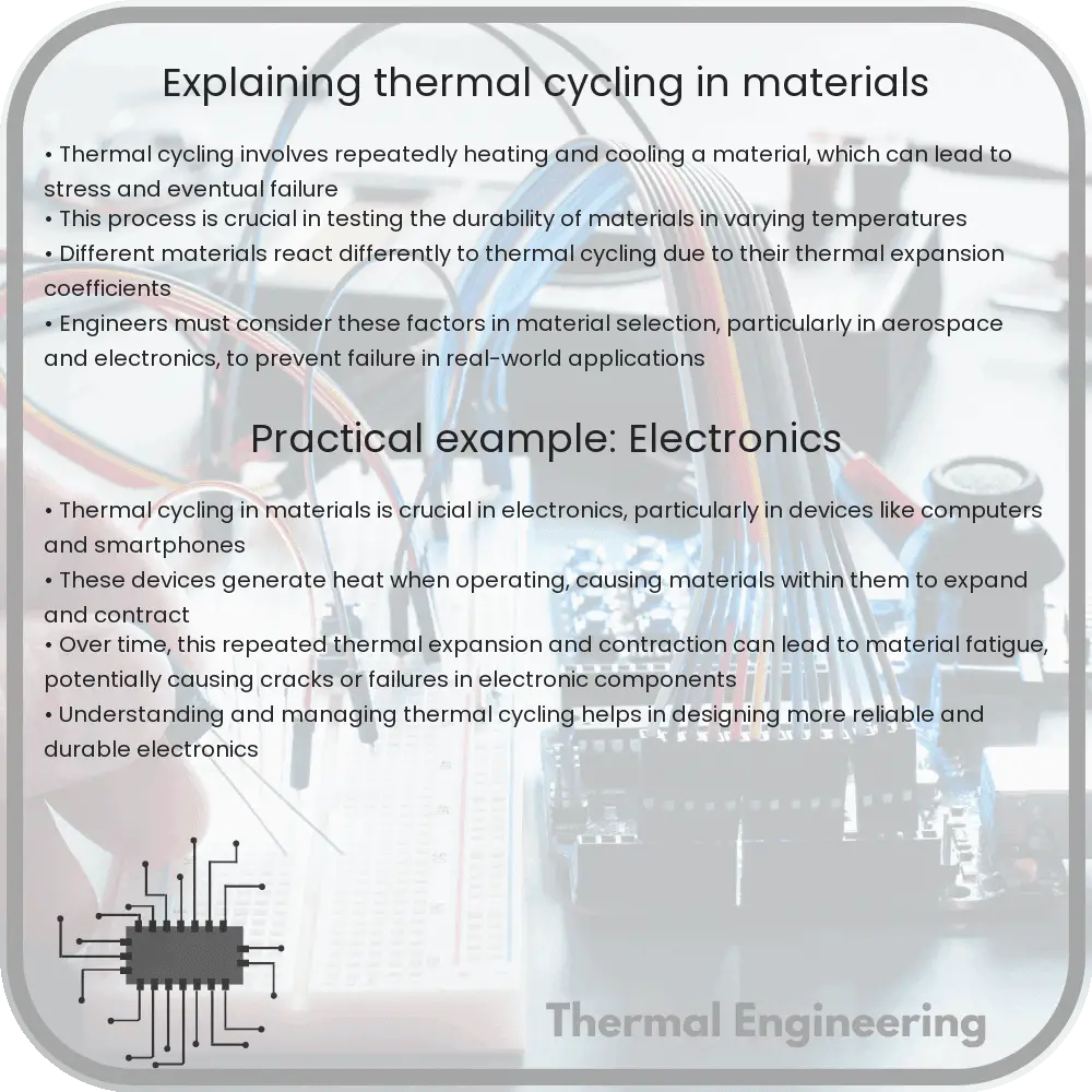
Thermal cycling refers to the process wherein a material is repeatedly exposed to varying temperatures. This can lead to thermal expansion and contraction, which can significantly affect the material’s properties over time. Industries such as aerospace, automotive, and electronics commonly encounter these challenges, as materials used in these fields are often subjected to extreme and fluctuating temperature conditions.

Effects of Thermal Expansion and Contraction

Materials expand when heated and contract when cooled. This behavior is described by the coefficient of thermal expansion (CTE), a material-specific constant that quantifies the change in size per degree change in temperature. The equation used to calculate the change in dimension of the material due to temperature change is:

\[ \Delta L = \alpha L_0 \Delta T \]

  • \(\Delta L\) is the change in dimension (such as length).
  • \(\alpha\) is the coefficient of thermal expansion.
  • \(L_0\) is the original dimension.
  • \(\Delta T\) is the change in temperature.

The differences in CTE among different materials can cause significant internal stresses when these materials are used in conjunction. For example, in electronics, solder joints are subjected to such stresses due to differences in CTE between the solder material and the electronic components, potentially leading to failure over time.

Stresses Induced by Thermal Cycling

When a material undergoes thermal cycling, it repetitively experiences expansion and contraction, leading to fatigue. This fatigue is caused by the stress induced from constrained expansion or contraction, structural changes at the microscale, or flaws that may propagate as cracks over many cycles.

Real-world Applications and Concerns

Understanding thermal cycling is critical for several applications:

  1. Aerospace: Components in satellites and spacecraft experience extreme thermal variations. Engineering these components requires materials that can withstand thermal cycling without degrading.
  2. Automotive: Engine parts and exhaust systems deal with high temperatures during operation and cool down when the vehicle is turned off, necessitating materials designed to handle this stress without cracking.
  3. Solar Panels: The performance and longevity of solar panels can be influenced by thermal cycling, as temperature changes from day to night stress the materials.

Mitigating the Effects of Thermal Cycling

To mitigate the negative effects of thermal cycling, engineers employ several strategies:

  • Using materials with a low coefficient of thermal expansion to reduce the magnitude of expansion and contraction.
  • Designing structures to accommodate movement due to thermal stresses, such as incorporating expansion joints or stress relief features.
  • Applying surface treatments or coatings that can help absorb some of the stress and protect the underlying material.
  • Selecting materials that are more resistant to fatigue from repeated thermal cycling.

By carefully selecting materials and designing with thermal cycling in mind, engineers can enhance the durability and performance of components across various industries. Understanding the fundamental principles of thermal cycling helps in predicting the lifecycle and safety of materials and structures under temperature fluctuations.

How Do Heat Shields Protect Spacecraft?

Learn how heat shields protect spacecraft from extreme temperatures during atmospheric re-entry and approaches to hot celestial bodies.

How Do Heat Shields Protect Spacecraft?

How Do Heat Shields Protect Spacecraft?

When a spacecraft re-enters Earth’s atmosphere or approaches a hot celestial body, it is exposed to extreme temperatures that could easily destroy it without sufficient protection. This is where heat shields play a crucial role. Heat shields are engineered to protect spacecraft from the severe heat and energy generated during high-speed travel through an atmosphere.

The Science Behind Heat Shields

Upon atmospheric entry, a spacecraft faces intense friction from air particles, which leads to the generation of extreme heat. The main function of a heat shield is to manage this heat and ensure the structural integrity and safety of the spacecraft and its contents. This is achieved primarily through two mechanisms: reflecting heat away and absorbing heat.

Materials Used in Heat Shields

  • Ablative Material: This material chars and erodes away when exposed to high temperatures, absorbing intense heat and removing it through the shedding of the material. Commonly used ablative materials include reinforced carbon-carbon composites or heat-resistant plastics.
  • Refractory Materials: These materials can withstand extremely high temperatures without melting or degrading. Examples include tungsten and silica-based fibers.
  • Insulative Coatings: Certain heat shields incorporate coatings that reflect radiant heat, further protecting the spacecraft’s hull from the intense thermal energy.

Design Considerations for Heat Shields

Designing an effective heat shield involves several considerations:

  1. Shape: The shape of the heat shield affects its ability to manage heat. Typically, a blunt shape is preferred as it creates a shock wave that deflects most of the heat away from the spacecraft.
  2. Thickness and Material Composition: The thickness and specific composition of the materials used in the heat shield must be carefully calibrated based on the expected heat loads and duration of exposure.
  3. Weight: Adding a heat shield increases the overall mass of the spacecraft, which impacts the fuel efficiency and cost. Engineers must strike a balance between protection and added weight.

Case Study: Re-entry of Space Shuttles

The Space Shuttle program provides a notable example of heat shield engineering. The shuttles were equipped with a Thermal Protection System (TPS), which included tiles made of silica fibers. These tiles could withstand temperatures up to 1,650 degrees Celsius (about 3,000 degrees Fahrenheit) and were crucial for the shuttles’ safe re-entry into Earth’s atmosphere.

The Future of Heat Shield Technology

As missions aim to explore further into our solar system, the demands on heat shield technology grow. Innovative materials and designs, such as heat shields that can withstand multiple entries or those designed for the intense conditions of Venus or Mars, are under development. The ongoing advancements in material science and aerospace engineering continue to push the boundaries of what is possible in spacecraft design and protection.

Understanding heat shields not only provides insight into spacecraft design but also highlights the remarkable intersection of physics and engineering required to explore beyond our planet safely.