Facebook Instagram Youtube Twitter

How Does Viscous Heating Affect Fluids?

Learn about viscous heating, the generation of internal heat in fluids under shear stress, crucial in fluid dynamics and engineering applications.

How Does Viscous Heating Affect Fluids?

Understanding Viscous Heating in Fluids

Viscous heating is an important phenomenon in fluid dynamics, particularly relevant in engineering applications where fluid motion and heat transfer are involved. This effect arises when the viscosity of a fluid causes it to generate internal heat as it flows, particularly under conditions of high shear stress or high rates of deformation.

What Causes Viscous Heating?

Viscous heating occurs due to the internal friction within a fluid, which is a result of its viscosity. Viscosity is a measure of a fluid’s resistance to gradual deformation by shear or tensile stress. When a fluid is forced to flow, such as through a pipe or around an object, the layers of the fluid move at different speeds, creating shear stress. The energy used to overcome this friction is converted into heat, leading to an increase in the temperature of the fluid.

The Physics Behind Viscous Heating

The amount of heat generated by viscous forces can be estimated by considering the work done against these forces. The formula for viscous heating, in terms of shear stress (τ) and the rate of strain (dγ/dt), is given by:

Q = τ * (dγ/dt)

where:

  • Q is the heat generated per unit volume,
  • τ is the shear stress,
  • dγ/dt is the rate of strain or shear rate.

This equation indicates that the generated heat depends directly on both the shear stress and the rate at which the fluid is deformed.

Effects of Viscous Heating in Engineering

In engineering, understanding and managing viscous heating is crucial, particularly in systems involving lubrication, polymer processing, and high-speed flows. Some of the effects and implications include:

  1. Temperature Increase: Viscous heating can lead to significant temperature increases in a fluid, affecting its viscosity and thereby influencing the overall flow characteristics.
  2. Changing Material Properties: For materials like polymers, increased temperature can change physical properties such as viscosity and elasticity, impacting processing techniques like extrusion and injection molding.
  3. Energy Efficiency: In systems like hydraulic circuits, excessive viscous heating represents a loss of energy efficiency, as more power is required to maintain fluid flow against rising resistance due to increased fluid temperature.
  4. Equipment Design: Engineers must design equipment to either minimize viscous heating effects or accommodate the resulting temperature changes through cooling systems or material selection.

Case Studies and Practical Applications

One practical application of viscous heating can be seen in the lubrication systems of machinery, where the heat generated by viscous forces can lead to the thinning of oil. This requires the system to have mechanisms to dissipate heat effectively or use lubricants that can perform under a range of temperatures. Another example is in the food processing industry, where viscous heating is used to cook or modify the texture of products via controlled shear stress in the processing equipment.

In summary, viscous heating plays a crucial role in the behavior of fluids under flow and has multiple implications in various engineering fields. Properly managing this effect is essential for optimizing system performance and ensuring the reliability and efficacy of engineering applications involving fluid dynamics.


What Is a Thermal Interface Material?

Learn about Thermal Interface Materials (TIMs), essential for managing heat in electronic devices to enhance performance and longevity.

What Is a Thermal Interface Material?

What Is a Thermal Interface Material?

Thermal Interface Material (TIM) is a critical component in the engineering and electronics fields, playing a pivotal role in the management of heat in electronic devices. As electronic devices operate, they generate heat, which can degrade their performance and lifespan if not properly dissipated. TIMs are used to enhance thermal transfer between heat-generating components and heat dissipation parts, such as heatsinks.

Types of Thermal Interface Materials

There are several types of TIMs, each with unique properties and applications:

  • Thermal Greases: Also known as thermal paste, these are viscous fluid substances that fill air gaps and microscopic irregularities between the surfaces.
  • Thermal Pads: These are pre-cut pieces of soft material that act as a filler between two surfaces. They are easier to use but generally offer lower thermal conductivity compared to greases.
  • Phase Change Materials: These materials change state from solid to liquid at certain temperatures to enhance thermal conductivity through the interface.
  • Thermal Tapes and Adhesives: These are stickier and can be used not only to improve thermal conductivity but also to mechanically bond components together.
  • Metal-based TIMs: Composed of metals like silver or aluminum, these TIMs provide a very high level of thermal conductivity, suitable for high-performance applications.

Key Properties of TIMs

The effectiveness of a TIM is determined by several key properties:

  • Thermal Conductivity: This is a measure of a material’s ability to conduct heat, expressed in watts per meter-Kelvin (W/m*K). A higher number indicates better conductivity.
  • Thermal Impedance: This is a measure of resistance to heat flow, typically given in degrees Celsius-inch2/watt (°C-in2/W). Lower values indicate better performance.
  • Viscosity: Relevant for greases and gels, this refers to the thickness of the TIM and its ability to flow and fill gaps.
  • Adhesion: The ability of tape or adhesive TIMs to stick components together and maintain contact throughout temperature variations.

Application and Importance

TIMs are essential in numerous electronic applications such as in processors (CPUs, GPUs), LED lighting, and power electronics. The correct application of TIM affects not only the efficiency of heat dissipation but also the overall performance and lifespan of the electronic device. Poor thermal management can lead to overheating, reduced performance, device failure, and even hazards in extreme cases.

Conclusion

Understanding and selecting the right Thermal Interface Material is vital for ensuring effective thermal management in electronic devices. It ensures that devices operate within optimal thermal conditions, thereby enhancing performance, reliability, and longevity. As devices continue to shrink in size while increasing in power, the role of TIMs becomes even more crucial in the design and maintenance of modern electronic systems.

Basics of Microfluidics Technology

Guide to understanding Microfluidics, a technology manipulating tiny fluid volumes for diverse applications like diagnostics and environmental monitoring.

Basics of Microfluidics Technology

Introduction to Microfluidics Technology

Microfluidics is a field of engineering that deals with the study and manipulation of fluids at the microscale. It integrates principles from engineering, physics, chemistry, biochemistry, nanotechnology, and biotechnology to control fluids at scales typically less than a millimeter. This technology enables scientists and engineers to design systems that can handle small volumes of fluids with high precision and control, leading to advancements in various applications including medical diagnostics, environmental monitoring, and the development of new materials.

Key Principles of Microfluidics

Microfluidics operates on a scale where the behavior of fluids can be significantly different from what is observed in bulk systems. Some of the fundamental principles that govern microfluidics include laminar flow, diffusion, and capillary effects:

  • Laminar Flow: At the microscale, fluid flows are generally laminar, meaning that the fluids flow in parallel layers with minimal mixing. This characteristic is quantified by the Reynolds number (Re), which is low in microfluidic systems. The formula for Reynolds number is Re = ρ*u*L/μ, where ρ is the density, u is the flow velocity, L is the characteristic length, and μ is the viscosity.
  • Diffusion: In microfluidic channels, mass transport is often dominated by diffusion, which is the movement of molecules from areas of high concentration to low concentration. The time scale for diffusion can be calculated using the formula t = L2/D, where L is the distance and D is the diffusion coefficient.
  • Capillary Effects: Capillary action can be significant in microfluidic systems due to the small dimensions of channels. These effects allow for the passive movement of fluids without the need for external force or power.

Components of Microfluidic Systems

A typical microfluidic system consists of channels, pumps, valves, and detectors, each playing a crucial role in fluid manipulation and analysis:

  • Channels: Microscopic channels are etched or molded into materials such as silicon, glass, or polymers. These channels serve as pathways for transporting fluids.
  • Pumps: Fluid movement in microfluidic devices can be driven by various types of micropumps, including mechanical, electrokinetic, and piezoelectric pumps.
  • Valves: Microvalves control the flow of fluids, allowing the selective start, stop, and direction of flow within the microfluidic device.
  • Detectors: Optical, electrochemical, or mass-sensitive sensors can be integrated to analyze the fluid’s properties or the presence of specific chemicals or biological entities.

Applications of Microfluidics

One of the most significant impacts of microfluidics is in the field of healthcare, where it has revolutionized diagnostic techniques through the development of lab-on-a-chip devices. These compact devices automate multiple laboratory functions on a single chip, significantly reducing sample size, time, and cost:

  • Medical Diagnostics: Microfluidic devices are used in point-of-care testing for rapid diagnosis of diseases by analyzing small volumes of blood or saliva.
  • Drug Development: Microfluidics aids in high-throughput screening, enabling faster testing of pharmacological properties on cell cultures or microorganisms.
  • Environmental Monitoring: Portable microfluidic devices detect and analyze pollutants in air, water, or soil, helping in real-time monitoring of environmental conditions.

Challenges and Future Directions

Despite its numerous advantages, microfluidics faces challenges like integration complexity, manufacturing costs, and material limitations. Advances in materials science, 3D printing technology, and nanotechnology promise to overcome these hurdles, potentially leading to more innovative and accessible microfluidic devices.

In conclusion, microfluidics is a transformative technology that plays a critical role in advancing research and applications in various sectors. Its continual development is bound to unlock further potential, leading to broader impacts across science and engineering disciplines.

How Do Blowers Increase Fluid Velocity?

Learn how blowers utilize mechanical and fluid dynamics principles to enhance fluid velocity in HVAC and industrial applications.

How Do Blowers Increase Fluid Velocity?

How Do Blowers Increase Fluid Velocity?

Blowers are a common mechanical device used in various engineering applications ranging from heating, ventilation, and air conditioning (HVAC) systems to industrial processes. Their primary function is to move air or other gases with increased velocity, which is crucial for many system operations. Understanding how blowers increase fluid velocity involves a combination of fluid dynamics and mechanical engineering principles.

Basic Principle of Operation

A blower increases fluid velocity by converting mechanical energy from a motor into kinetic energy in the fluid. This process generally involves the following steps:

  • The blower’s motor turns a fan or impeller inside the housing.
  • The rotation of the fan blades accelerates the air or gas from the center of the fan outward through centrifugal force.
  • The design of the blower housing then directs this fast-moving fluid into a duct, pipe, or the open environment, depending on the application.

Component Contributions to Fluid Velocity Increase

The main components of a blower that contribute to the increase in fluid velocity include:

  • Impeller or Fan: The shape and speed of the impeller or fan blades are critical. As the blades rotate, they push air forward and outward due to aerodynamic forces generated by blade angles and speeds.
  • Blower Housing: The housing design plays a significant role in directing and controlling the flow of the air pushed by the impeller. A well-designed housing minimizes the loss of air pressure and velocity as the air exits the blower.
  • Motor: The power of the motor determines how fast the impeller can spin, directly affecting how quickly air is moved and accelerated.

Understanding Fluid Velocity: Bernoulli’s Principle

One important principle that explains how blowers increase fluid velocity is Bernoulli’s principle. It states that in a flowing fluid (air in the case of blowers), there is an inverse relationship between pressure and velocity. Mathematically, it is expressed as:

\[\frac{P}{\rho} + \frac{1}{2}v^2 + gz = constant\]

Where:

  • \(P\) is the fluid pressure,
  • \(\rho\) is the fluid density,
  • \(v\) is the fluid velocity,
  • \(g\) is the acceleration due to gravity,
  • \(z\) is the fluid elevation.

In the context of a blower, as the impeller accelerates the air, it converts some of the mechanical energy into velocity (\(v^2\) term), often at the cost of slightly lowering air pressure, which is consistent with Bernoulli’s principle.

Applications of Increased Fluid Velocity

Increased fluid velocity via blowers has numerous applications such as:

  • Ventilation Systems: Deliver fresh air into buildings or remove stale or contaminated air.
  • Cooling Processes: Enhance heat transfer in systems like air conditioners by moving cooler air more quickly over warm surfaces.
  • Pneumatic Transport: Transport particles suspended in the air across distances using the high speed of air.

Understanding how blowers function to increase fluid velocity not only underscores their importance in various industrial and environmental processes but also contributes to improving and innovating system efficiency and effectiveness.

Understanding Non-Newtonian Fluids

Learn about non-Newtonian fluids, materials with viscosity that changes under stress, differing from standard fluids like water.

Understanding Non-Newtonian Fluids

Understanding Non-Newtonian Fluids

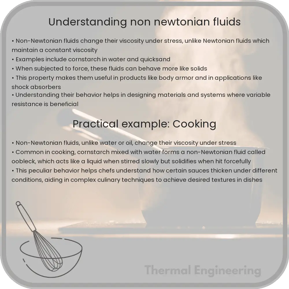
Non-Newtonian fluids are fascinating materials that behave differently from typical fluids like water or air, which follow Newton’s law of viscosity. The viscosity of a fluid is essentially a measure of its resistance to gradual deformation by shear stress or tensile stress. In non-Newtonian fluids, the viscosity changes when under force to either more liquid or more solid. This distinctive characteristic makes them incredibly useful in various applications, from everyday products to industrial processes.

Types of Non-Newtonian Fluids

Non-Newtonian fluids can be classified into several types based on how their viscosity changes in response to stress:

  • Shear-thickening (Dilatant) fluids: These fluids, such as cornstarch mixed with water, increase in viscosity or become more solid when agitated or stressed.
  • Shear-thinning (Pseudoplastic) fluids: Such as ketchup or blood, these decrease in viscosity under shear stress and become more fluid-like. This is why ketchup becomes easier to pour when you shake the bottle.
  • Thixotropic fluids: These materials take a finite time to attain a steady viscosity when the shear condition changes. For example, paint might feel thicker when initially stirred but becomes more fluid-like with continued stirring.
  • Rheopectic fluids: Opposite to thixotropic fluids, these fluids become more viscous or thick over time under stress.
  • Bingham plastics: Like toothpaste, these start to flow only after their yield stress, a specific stress threshold, has been exceeded.

These behaviors can be explained by different factors, including the composition of the fluid, the size and shape of particles within a fluid, and the interactions between the particles.

Mathematical Model

For Newtonian fluids, the viscosity (η) remains constant, described by the simple equation:

τ = η * γ

where τ is the shear stress and γ is the shear rate.

For non-Newtonian fluids, however, the relationship between shear stress and shear rate is not linear and can be expressed as:

τ = K * γn

  • K is the consistency coefficient.
  • n is the flow behavior index, where n < 1 for shear-thinning, n > 1 for shear-thickening, and n = 1 reverts to the Newtonian fluid behavior.

Applications

Non-Newtonian fluids have both practical and innovative applications across various fields:

  • Consumer Products: Everyday items like toothpaste, lotions, and creams are easier to handle and apply due to their non-Newtonian properties.
  • Industrial Processes: In industries, these fluids assist in processes where controlling the flow and spreadability is crucial—for instance, in food processing or the manufacture of sauces and dressings.
  • Protective Gear: Shear-thickening fluids are used in some modern body armors where they remain flexible under normal conditions and become solid under high-impact forces, providing additional protection.
  • Medical Applications: In the medical field, non-Newtonian gels are used in prosthetics and drug delivery systems where tailored flow properties can significantly improve performance and comfort.

In conclusion, non-Newtonian fluids challenge our traditional understanding of how liquids behave, opening up possibilities for innovative solutions in various industries. Their unique properties ensure they continue to be a subject of interest and innovation in both research and application.

How Do Tidal Power Plants Utilize Fluids?

Learn how tidal power, a renewable energy source, harnesses the ocean’s tides to generate electricity through innovative engineering techniques.

How Do Tidal Power Plants Utilize Fluids?

Understanding Tidal Power: Harnessing the Energy of Fluids

Tidal power, a form of hydropower, leverages the movement of water caused by tides to generate electricity. The gravitational pull of the moon, and to a lesser extent the sun, exerts a force on the Earth’s oceans, creating predictable patterns of high and low tides. Tidal power plants convert the energy from these fluid movements into electricity, providing a renewable and sustainable energy source. This article explores the fundamentals of how tidal power plants utilize these fluid dynamics.

Types of Tidal Power Systems

There are three primary types of tidal power setups:

  • Tidal Stream Generators: These devices function like underwater wind turbines, harnessing the kinetic energy of moving water.
  • Tidal Barrages: These are dams built across the opening of a tidal basin. They have gates that close when the tide is at its highest, and open as the tide lowers, using the potential energy difference between the high and low tides.
  • Dynamic Tidal Power: A theoretical approach involving a long barrier built at right angles to the coast, capturing potential energy without enclosing an area.

Working Principles of Tidal Power Plants

Tidal power plants predominantly operate on the principles of mechanical energy conversion. Below is an overview of the workings of tidal stream generators and tidal barrages.

Tidal Stream Generators

Kinetic Energy Conversion: In tidal stream systems, the kinetic energy of flowing seawater is converted directly into mechanical energy. As water flows through the turbines, it causes the turbine blades to rotate. These turbines are linked to generators, which transform the mechanical rotation into electrical energy. The energy output is directly proportional to the water speed through the turbine, where the kinetic energy (KE) can be described by the formula:

\[
KE = \frac{1}{2} m v^2
\]

Here, m represents the mass of the moving water, and v is the velocity of the water.

Tidal Barrages

Potential Energy Conversion: Tidal barrages exploit the potential energy generated by the difference in height (or head) between high and low tides. The barrage contains sluice gates that close during the incoming high tide and open as the tide recedes. The water retained during high tide creates a “tidal lagoon” with potential energy (PE) which is expressed as:

\[
PE = mgh
\]

where m is the mass of the water, g stands for acceleration due to gravity, and h is the height difference between the levels of water inside and outside the barrage. The controlled release of this water through turbines produces energy.

Challenges and Considerations

Despite its renewable nature, the implementation of tidal power must overcome several challenges:

  • Environmental Impact: Tidal systems can affect marine biodiversity, potentially disrupting habitats and affecting local ecosystems.
  • Location Constraints: Suitable locations for tidal power plants are limited to areas with significant tidal changes, such as coastal regions with large tidal ranges.
  • Economic Factors: High initial capital costs and the complexity of underwater construction make tidal power plants economically challenging to implement.

Conclusion

Tidal power plants use advanced engineering techniques to transform the natural ebbs and flows of ocean tides into valuable electrical energy. Through the use of tidal stream generators and tidal barrages, these plants capture kinetic and potential energy from tidal movements, contributing to the expanding portfolio of renewable energy sources crucial for sustainable development. Despite challenges such as environmental concerns and economic feasibility, tidal energy represents an innovative application of fluid mechanics in power generation.

Understanding Fluid Momentum Transfer

Explore the concept of fluid momentum transfer, a key aspect of fluid dynamics critical for optimizing engineering systems like pipes and turbines.

Understanding Fluid Momentum Transfer

Understanding Fluid Momentum Transfer

Fluid momentum transfer is a fundamental concept within the field of fluid dynamics, which is a branch of physics and engineering that deals with the behavior of fluids (liquids and gases). Understanding how momentum is transferred in fluids is essential for designing and optimizing various mechanical systems such as pipes, pumps, and turbines.

Basics of Fluid Momentum

Momentum, in the context of physics, refers to the quantity of motion of a moving body. For fluids, momentum is a product of the mass flow rate and the velocity of the fluid. It can be expressed as:

\[ P = m \cdot v \]

  • m – mass of the fluid
  • v – velocity of the fluid

Fluid momentum transfer involves the exchange or modification of this momentum due to forces acting on the fluid, such as pressure differences, gravitational forces, or interaction with solid surfaces.

Applications in Engineering

Engineers often need to analyze and control the momentum transfer in fluid systems to ensure efficient operation of devices and processes. Here are a few common applications:

  • Piping Systems: The design of piping systems to minimize loss of pressure and energy due to friction and turbulence.
  • Turbines: In turbines, the kinetic energy of fluids (often water or steam) is converted into mechanical energy. Understanding momentum transfer is critical in optimizing turbine efficiency and output.
  • Jet Engines: In jet engines, air is accelerated to produce thrust. Efficient transfer of the air’s momentum to the engine thrust is key to performance.

Key Equations and Principles

The fundamental principles governing fluid momentum transfer include the conservation of momentum, Bernoulli’s equation, and Newton’s laws, which provide a framework to predict and analyze fluid behavior under various conditions.

One of the principal equations is the Momentum Equation which, in its conservation form, is stated as:

\[ \frac{\partial (\rho \cdot v)}{\partial t} + \nabla \cdot (\rho \cdot v \cdot v) = -\nabla p + f \]

  • ρ – fluid density
  • v – fluid velocity vector
  • p – pressure
  • f – external forces (e.g., gravity, friction)

Challenges in Fluid Momentum Transfer

One of the main challenges in fluid dynamics and momentum transfer is dealing with turbulent flow. Turbulence is a complex, irregular type of flow that can lead to increased resistance and energy loss in fluid-moving systems. Accurately predicting and mitigating turbulence effects is critical for efficient system design.

Additionally, the shift to sustainable and renewable energy sources poses both challenges and opportunities in fluid momentum transfer applications. Engineers must innovate to harness kinetic energies more effectively, particularly in water and wind turbines.

Conclusion

Understanding fluid momentum transfer is crucial for the optimization and innovation of many engineering systems. By manipulating the equations and principles discussed, engineers can design more efficient transportation systems, energy generation methods, and industrial processes, ultimately leading to advancements in technology and conservation of resources.

What Is the Strouhal Number in Fluids?

Learn about the Strouhal number, a key dimensionless quantity in fluid mechanics used to analyze oscillating flow phenomena.

What Is the Strouhal Number in Fluids?

What Is the Strouhal Number in Fluids?

The Strouhal number (St) is a dimensionless quantity in fluid mechanics that describes oscillating flow mechanisms. It is particularly useful in the study and prediction of fluid-induced vibrations, vortex shedding, and oscillatory flow phenomena. The concept is named after the Czech physicist, Vincenc Strouhal, who first noticed the effect in 1878 while working with wires subjected to air flows.

Definition and Formula

The Strouhal number is defined as the ratio of inertial forces due to the unsteadiness of the flow to inertial forces due to the convection of the flow. This can be mathematically expressed as:

St = f * L / U

  • f is the frequency of vortex shedding.
  • L represents a characteristic linear dimension (typically the diameter in cases of cylindrical objects).
  • U is the velocity of the flow.

This dimensionless parameter helps engineers and scientists understand flow patterns around objects, and predict the flow-induced vibrations, which is crucial for the design of various structures like bridges, power lines, and tall buildings, where vortex shedding can lead to oscillations that may affect structural integrity.

Applications of the Strouhal Number

The Strouhal number has wide-ranging applications in engineering and physics. Some of the notable applications include:

  • Aerospace: In aircraft design, engineers use the Strouhal number to calculate the lift and drag forces, which affect the aircraft’s stability and fuel efficiency.
  • Civil Engineering: It helps in designing structures that endure environmental loads without experiencing destructive resonance, such as in the case of the Tacoma Narrows Bridge disaster in 1940.
  • Marine Engineering: In ship design, understanding vortex shedding and its related effects can help prevent structural damage and improve performance through better hull shapes.
  • Environmental Science: The Strouhal number is used to model and predict wind patterns and their effect on various natural and human-made structures.

Significance in Research and Development

The importance of the Strouhal number extends beyond preventing structural failures. It is also useful in the development of technology aimed at harnessing renewable energy sources such as wind turbines and tidal generators. By studying the Strouhal number, scientists and engineers can optimize the design of turbine blades to maximize efficiency and minimize wear due to oscillatory forces.

In summary, the Strouhal number is a crucial tool in fluid dynamics, offering valuable insights into how objects interact with fluid flows. Its applications impact various fields of engineering and environmental science, highlighting its importance in both academic research and practical engineering solutions.

What Is Forced Convection in Heat Transfer?

Learn about forced convection in heat transfer, a process where fluid motion is induced by external means like fans or pumps to control and enhance heat movement.

What Is Forced Convection in Heat Transfer?

Understanding Forced Convection in Heat Transfer

Convection is one of the primary mechanisms of heat transfer and plays a critical role in both natural phenomena and engineering applications. Forced convection, a subtype of this mechanism, occurs when a fluid’s movement is generated by an external source like a fan, pump, or other mechanical means. In this article, we’ll explore the concept of forced convection, its fundamental principles, and its importance in engineering.

Basic Concepts and Principles

Heat transfer via convection involves the transfer of heat by the physical movement of fluid, which can be a liquid or a gas. There are two types of convection: natural (or free) convection and forced convection. In natural convection, fluid motion is caused by buoyancy forces that result from density variations due to temperature differences within the fluid. In contrast, in forced convection, the fluid is moved by external means, and the heat transfer is independent of the natural buoyancy effects.

The rate of heat transfer in forced convection is influenced by several factors, including the fluid’s velocity, its properties (such as viscosity, thermal conductivity, and specific heat), the surface area over which heat transfer occurs, and the temperature difference between the surface and the fluid.

Mathematical Representation

The heat transfer rate in forced convection can be expressed by Newton’s Law of Cooling:

\[
q = h \times A \times (T_s – T_f)
\]

where:

  • q is the rate of heat transfer (in watts, W),
  • h represents the heat transfer coefficient (in watts per square meter per degree Celsius, W/(m2°C)),
  • A is the surface area through which heat is being transferred (in square meters, m2),
  • Ts is the surface temperature (in degrees Celsius, °C),
  • Tf is the fluid temperature (in degrees Celsius, °C).

The heat transfer coefficient, h, depends on the fluid properties, flow velocity, and flow geometry, and is generally determined experimentally.

Applications of Forced Convection

Forced convection is extensively used in various engineering systems to enhance heat transfer. Some common applications include:

  • Radiators in cars: These use fans to blow air through the radiator coil to cool the engine coolant circulating within.
  • Air conditioning systems: Forced convection is utilized to circulate cool air within a room or building.
  • Electronic cooling: Fans are often used in computers and other electronic devices to maintain optimal operating temperatures.
  • Heat exchangers: These devices transfer heat between two or more fluids and often use forced convection to enhance the heat transfer efficiency.

Conclusion

Forced convection is a vital principle in thermal engineering that allows for controlled and efficient movement of heat across different mediums. By understanding and harnessing this process, engineers can design systems that effectively manage temperature and improve energy efficiency in various applications, from industrial machinery to household electronics.

By exploring the principles of forced convection, we gain a deeper insight into the sophisticated methods used in modern engineering to control and manipulate thermal energy, ensuring that equipment operates within safe, efficient parameters.

Fluid Mechanics in Urban Water Systems

Learn how fluid mechanics principles optimize urban water systems for distribution, sanitation, and efficiency.

Fluid Mechanics in Urban Water Systems

Understanding Fluid Mechanics in Urban Water Systems

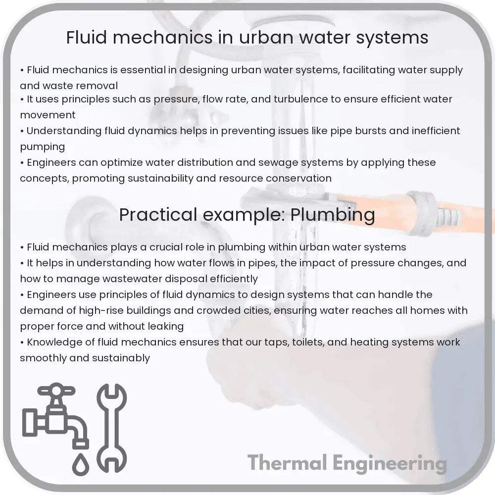
Fluid mechanics, a branch of physics and engineering, concerns the behavior of fluids (liquids and gases) in motion. In urban water systems, fluid mechanics plays a crucial role in ensuring efficient water distribution, sanitation, and drainage. This article explores how principles of fluid mechanics are applied to manage and maintain water flow within cities, enhancing both sustainability and accessibility.

Basics of Fluid Dynamics

At the core of fluid mechanics are the principles that describe how fluids behave and interact with their environment. There are two key concepts:

  • Laminar and Turbulent Flow: Laminar flow describes fluid moving smoothly and consistently in parallel layers, with little disruption between them. Conversely, turbulent flow is chaotic and characterized by small whirlpools known as eddies. The type of flow affects the design of pipe systems, with laminar flow being more desirable for minimizing friction and energy loss.
  • Continuity and Bernoulli’s Equation: The continuity equation, given by A1v1 = A2v2 (where A is the cross-sectional area of a pipe and v is the velocity of the fluid), helps engineers ensure mass conservation in fluid flow. Bernoulli’s equation, P + ½ρv2 + ρgh = constant (where P is pressure, ρ is fluid density, v is velocity, g is acceleration due to gravity, and h is height), is pivotal in understanding how energy is conserved in flowing fluids.

Fluid Mechanics in Water Supply Systems

Urban water supply systems require meticulous planning and management to deliver water efficiently from treatment facilities to consumers. Key applications of fluid mechanics include:

  • Pipe Design: The diameter and material of pipes are selected based on desired flow rates and minimal friction loss, calculated using principles like the Darcy-Weisbach equation ΔP = f(L/D)½ρv2, where ΔP is the pressure drop, f is the friction factor, L is pipe length, and D is diameter.
  • Pump Systems: Pumps are necessary to move water against gravity and over long distances. The pump head, defined as the height that a pump can raise water through atmospheric pressure and friction losses, is critical for maintaining adequate pressure and flow in water distribution.

Fluid Mechanics in Wastewater Treatment

The role of fluid mechanics extends to wastewater management, ensuring pollution control and public health protection:

  • Sedimentation Tanks: These tanks are designed using Stoke’s Law, v = g(d2(ρp – ρf)/(18μ), where v is settling velocity, d is particle diameter, ρp is particle density, ρf is fluid density, μ is dynamic viscosity, and g is gravitational acceleration. This formula helps calculate the size and settling time for suspended solids to separate from the water.
  • Aeration Systems: Aeration promotes microbial degradation of organic material in water. Proper air distribution and diffuse systems are designed based on fluid dynamic principles to maximize contact between air and water, thereby enhancing the efficiency of biological treatment processes.

In summary, the principles of fluid mechanics are essential for the design and operation of urban water systems. By applying concepts such as laminar and turbulent flows, continuity, and Bernoulli’s equation, engineers can optimize these systems for both performance and environmental compliance, ensuring that urban populations have access to safe, reliable water services.