Facebook Instagram Youtube Twitter

Temperature control in microelectromechanical systems (MEMS)

An in-depth look at the challenges and strategies of temperature control in MicroElectroMechanical Systems (MEMS), critical for device performance and longevity.

Temperature control in microelectromechanical systems (MEMS)

Understanding Temperature Control in MicroElectroMechanical Systems (MEMS)

MicroElectroMechanical Systems, or MEMS, are integral components in various applications ranging from automotive systems to consumer electronics and medical devices. A key challenge in the utilization and reliability of MEMS is managing and controlling temperature, as these tiny devices are sensitive to thermal variations. This article discusses the importance of temperature control in MEMS and how it’s achieved in practice.

The Impact of Temperature on MEMS

Temperature changes can significantly affect the performance, reliability, and longevity of MEMS devices. Some of the key impacts include:

  • Thermal Expansion: Different materials in MEMS may expand at different rates, leading to stress and possible structural damage.
  • Sensitivity and Accuracy: Sensors in MEMS, such as accelerometers or pressure sensors, can show altered readings if the device overheats or becomes too cold.
  • Power Efficiency: Battery-operated MEMS devices, like those in wearables, can experience reduced energy efficiency under temperature extremes.

Methods of Temperature Control in MEMS

To mitigate these impacts, several strategies are employed to control the temperature in MEMS devices:

  1. Material Selection: Choosing materials with matching thermal expansion properties or that are inherently resistant to temperature-induced stress.
  2. Thermal Buffers: Integrating materials that serve as thermal buffers, absorbing and dissipating unwanted heat, is common in MEMS design.
  3. Thermal Isolation: Structures or coatings that isolate the sensitive parts of the MEMS from thermal sources can be used to reduce the effects of temperature fluctuations.
  4. Active Cooling Systems: In high-power applications, active cooling solutions like micro fans or Peltier coolers may be implemented to maintain optimal operating temperatures.
  5. Feedback Systems: Utilizing integrated temperature sensors within MEMS to dynamically adjust operations or power settings based on current temperature readings.

Case Study: MEMS in Smartphones

In the context of consumer electronics such as smartphones, MEMS devices like gyroscopes and accelerometers play a crucial role. These devices must operate reliably in various environmental conditions that a phone may be exposed to. Manufacturers often integrate passive thermal management solutions, such as specific PCB designs that help dissipate heat away from the MEMS sensors. Moreover, the software may adjust sensor sensitivity or recalibrate the outputs depending on the internal temperature detected by the smartphone’s thermal sensors.

Conclusion

Temperature control in MEMS is a critical facet of the broader field of MEMS design and manufacturing. By understanding and implementing various thermal management techniques, engineers can enhance the performance and durability of MEMS in diverse applications. As technology continues to advance, the integration of smart thermal management strategies will play a pivotal role in the evolution of next-generation MEMS devices.

For anyone intrigued by MEMS technology or involved in its application, appreciating the complexities of temperature control is essential for developing more reliable and efficient systems. This knowledge not only ensures the better performance of MEMS-based devices but also opens up new possibilities for innovations in this fascinating area of engineering.
7 Types of Stirling Engines for External Combustion Applications

Learn about the Stirling engine, an efficient external combustion engine utilizing different heat sources for power.

7 Types of Stirling Engines for External Combustion Applications

Understanding Stirling Engines: 7 Types for External Combustion Applications

The Stirling engine, named after Robert Stirling who invented it in 1816, is a type of external combustion engine. Unlike internal combustion engines where the fuel combustion happens inside the engine itself, Stirling engines feature combustion occurring outside of the engine, which brings about various advantages including greater efficiency, quieter operation, and the ability to use multiple types of heat sources. These engines operate on the Stirling cycle, which involves cyclic compression and expansion of air or other gas at different temperature levels, thereby converting thermal energy into mechanical power.

There are numerous designs and configurations of Stirling engines, adapted for different applications and power needs. Here we explore seven popular types of Stirling engines:

  1. Alpha Stirling Engine

    This type has two separate power pistons in separate cylinders, one hot and one cold. The hot cylinder is situated at the heat source, whereas the cold one is situated at the cooling source. The transfer of gas between the cylinders drives the pistons and generates mechanical power. This design generally offers high power output and efficiency.

  2. Beta Stirling Engine

    The Beta configuration utilizes a single cylinder with a hot end and a cold end. It features a piston-displacer that moves the working gas between the heated and cooled areas of the cylinder. The same cylinder houses a power piston integrated directly into the displacer, or at least connected closely to it, which helps in simplifying the design and improving responsiveness.

  3. Gamma Stirling Engine

    The Gamma type is a variation of the Beta where the power piston and the displacer are in separate but connected cylinders. This arrangement allows for greater flexibility in design and can be easier to build, while still maintaining good efficiency and power output.

  4. Free-Piston Stirling Engine

    This variant does not use a conventional crankshaft. Instead, it relies on the movement of one or more pistons that are designed to be dynamically balanced. The movement can be used directly to generate power or to drive a linear generator for electrical power production. Free-piston Stirling engines are particularly noted for their smooth operation and high efficiency.

  5. Ringbom Stirling Engine

    Named after the engineer who developed it, the Ringbom Stirling engine eliminates the need for a mechanical linkage (such as a crankshaft) to operate the displacer. Instead, it uses a configuration where the displacer is driven by differences in pressure or thermal expansion mechanisms, simplifying the overall design and reducing maintenance needs.

  6. Rotary Stirling Engine

    Unlike traditional piston-based designs, rotary Stirling engines operate using a rotary displacer. This development allows the engine to potentially reduce mechanical complexity and wear while proving easy to integrate into applications where a compact and robust engine is beneficial.

  7. Fluidyne Stirling Engine

    This type of engine combines Stirling cycle with a liquid pump. The most common fluid used is water. Fluidyne engines have an advantage in simplicity and low-cost materials and are easy to build, making them an excellent choice for low-power applications and educational purposes.

Each type of Stirling engine presents a unique set of characteristics tailored to different applications, ranging from solar power generation to underwater power systems and even space propulsion. The adaptability in fuel sources—from solar to geothermal and biofuels—makes Stirling engines a versatile and environmentally friendly option in today’s diverse energy landscape. Understanding the types and applications of Stirling engines can be fundamental for engineers and innovators looking to harness alternative energy sources effectively.

4 Types of Scroll Compressors for HVAC and Refrigeration

Learn about scroll compressors in HVAC and refrigeration, their types, and how they enhance system efficiency and reliability.

4 Types of Scroll Compressors for HVAC and Refrigeration

Understanding Scroll Compressors in HVAC and Refrigeration Systems

Scroll compressors are essential components in modern HVAC (Heating, Ventilation, and Air Conditioning) and refrigeration systems. These devices are preferred for their efficiency and reliability, crucial in systems that require continuous operation. Scroll compressors operate by compressing air or refrigerant between two interleaving scrolls: one stationary and one that moves in a tight orbital motion. This unique movement reduces the number of moving parts, leading to fewer mechanical issues and quieter operation.

We will explore four main types of scroll compressors, looking at how each type supports different applications within the fields of HVAC and refrigeration.

Fixed Speed Scroll Compressors

Fixed speed scroll compressors operate at a constant speed, delivering a steady amount of cooling capacity. Unlike variable speed compressors, fixed speed types do not adjust their motor speed based on the load demand. This can lead to less complexity and potentially a longer lifespan due to reduced wear and tear from constant speed cycling.

  • Advantages: Simplicity in design, generally lower costs, and reliability.
  • Disadvantages: Less efficient in energy use compared to variable speed compressors, as they run at full capacity even when it’s not necessary.

Variable Speed Scroll Compressors

Variable speed scroll compressors can adjust their speed based on the cooling or heating demand. This type of compressor uses an inverter to vary the voltage and frequency of its electrical input, allowing precise control over compressor speed. The ability to adjust speeds enhances the efficiency of the system, potentially reducing energy costs significantly.

  • Advantages: Improved energy efficiency, better humidity control, and quieter operation.
  • Disadvantages: Higher initial cost and more complex electronic controls.

Digital Scroll Compressors

Digital scroll compressors provide a unique approach to modulating capacity. These compressors can operate in two stages: full load and no load (unloaded). During the unloaded phase, the internal bypass mechanism allows the compressor to separate the scrolls, effectively stopping compression without stopping the motor. This cycling between loaded and unloaded states allows for capacity modulation.

  • Advantages: High efficiency and excellent part-load operation, capable of closely matching load requirements without frequent starts and stops.
  • Disadvantages: More complex mechanical design, which may influence maintenance needs and costs.

Tandem Scroll Compressors

Tandem scroll compressors consist of two or more scroll compressors connected in parallel within the same system. This setup allows for more flexibility in capacity control, as one compressor can be operated while the other is idled, depending on the load requirements. Tandem compressors are often used in larger commercial HVAC systems where load variations across multiple zones are common.

  • Advantages: Flexible capacity management, improved efficiency at partial loads, and potential redundancy if one compressor fails.
  • Disadvantages: Higher initial installation cost and complexity in system controls.

In conclusion, scroll compressors are versatile and efficient options for modern HVAC and refrigeration systems. Understanding the different types of scroll compressors helps in selecting the right compressor based on specific application needs, whether for residential comfort, commercial cooling, or precision-controlled environments such as data centers and laboratories.

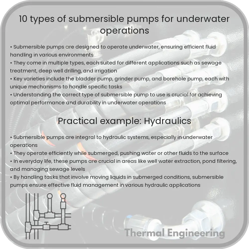
10 Types of Submersible Pumps for Underwater Operations

Learn about 10 different types of submersible pumps used in various underwater operations, from residential to industrial applications.

10 Types of Submersible Pumps for Underwater Operations

Understanding Submersible Pumps: 10 Types for Underwater Operations

Submersible pumps, vital tools for a wide range of underwater operations, dive deep into liquids to facilitate fluid movement to the surface. Unlike external pumps, they push water to the surface, thereby operating more efficiently under submerged conditions. These pumps are crucial in numerous applications, including water extraction, oil industries, and wastewater management.

1. Bladder Pumps

Bladder pumps prevent contamination between the fluid and pump mechanism, making them ideal for environmental water sampling and monitoring applications. They function by inflating and deflating a bladder with air, causing water to be drawn in and then expelled.

2. Grinder Pumps

Grinder pumps are equipped with cutting systems used to grind solid waste into smaller pieces so they can be transported through smaller diameter pipes without blockages. These are typically used in municipal, commercial, and domestic wastewater applications.

3. Well Pumps

Also known as submersible borehole pumps, these are common in residential and commercial water extraction, using a long, cylindrical shape that fits inside a well casing. They provide a steady water supply from deep underground sources.

4. Fountain Pumps

Designed primarily for aesthetics as well as aeration in ponds and fountains, fountain pumps keep water circulating to prevent stagnation and provide visual effects through fountain heads or sculptures.

5. Sump Pumps

Used to prevent groundwater from entering basements or crawl spaces, sump pumps automatically turn on when water reaches a certain level. They are crucial in areas prone to flooding, channeling water away from foundations.

6. Utility Pumps

Utility pumps are versatile submersibles for general water transfer applications, suitable for temporary setups in instances such as emptying flooded basements, pools, or even removing water off flat roofs.

7. Bilge Pumps

Primarily used in boats to remove bilge water, these pumps are critical for maintaining the boat’s buoyancy. Bilge pumps help in managing emergency situations and regular water accumulation due to weather or internal leaks.

8. Trash Pumps

Capable of handling suspensions containing solids like leaves, twigs, and pebbles, trash pumps are robust enough for construction sites, agricultural fields, and flood-hit areas where water loaded with debris needs to be cleared.

9. Magnetic Drive Pumps

Magnetic drive pumps use magnetic couplings to create the impeller’s rotational force without direct contact. This design reduces the risk of leaks, making them suitable for handling hazardous liquids in chemical and laboratory applications.

10. Cryogenic Pumps

Designed for extremely low temperatures, cryogenic pumps handle liquefied gases such as liquid nitrogen and liquid helium. Their primary application is in superconductor technology and medical fields, where high-purity gases are required.

Understanding the different types of submersible pumps and their specific uses helps in choosing the right pump for the right application, ensuring efficiency and longevity of service. From residential water supply to managing industrial waste, submersible pumps adapt across scenarios, proving their indispensability in fluid management technology.

5 Types of Radial Turbines in Power and Propulsion Systems

Learn about radial turbines, their types such as centrifugal and inflow turbines, and their applications in power generation and propulsion.

5 Types of Radial Turbines in Power and Propulsion Systems

Introduction to Radial Turbines

Radial turbines are a type of turbomachinery widely utilized in various applications in both power generation and propulsion systems. These turbines convert the kinetic and thermal energy of a fluid into rotational energy, which then typically drives a load such as an electrical generator or a propeller. Distinctive for their radial flow outgoing from the center, these turbines are preferred for their compactness, efficiency, and robust performance under high pressure and temperature conditions.

Key Types of Radial Turbines

Understanding the different types of radial turbines helps in selecting the right turbine for a specific application. Here are five common types of radial turbines:

  • Centrifugal Flow Radial Turbine
  • This is the most common type of radial turbine. In centrifugal flow turbines, the fluid enters the turbine wheel near its axis and flows outward along the radius under the influence of centrifugal forces. These turbines are typically used in small gas turbines and turbochargers.

  • Mixed Flow Radial Turbine
  • A mixed flow radial turbine combines aspects of both radial and axial flow. The fluid’s exit flow has components of both radial and axial directions, offering a compromise between compactness and efficiency at various speeds and loads. This type is often used in applications such as small to medium water turbines.

  • Radial Inflow Turbine
  • Radial inflow turbines feature a flow that reverses into the rotor inward along the radius. These are predominantly used in applications requiring compact turbine designs, such as in automotive turbochargers and some jet engines.

  • Diagonal Flow Radial Turbine
  • Also known as a mixed Radial-Axial Turbine, the diagonal flow turbine allows the fluid to enter radially but exit in a diagonal direction, combining the principles of both radial and axial turbines. This offers better energy extraction efficiency and is useful in high-power applications such as large gas turbines.

  • Reverse Radial Turbine
  • In the reverse radial turbine, the fluid enters the turbine at the outer radius and exits centrally. This reverse mechanism can be advantageous in specific niche applications where reversing the flow direction improves integration or efficiency.

Applications of Radial Turbines

Radial turbines are not just diverse in types but also in their applications:

  • Power Generation: Used in steam and gas turbines for electricity production, especially in combined heat and power (CHP) plants.
  • Automotive: Integral to turbochargers in internal combustion engines to boost engine power without significantly increasing engine size or emissions.
  • Aerospace: Employed in aircraft APUs (Auxiliary Power Units) and turbopumps in rocket engines.
  • Marine: Used in marine propulsion systems, particularly in turbocharged diesel engines, enhancing power and efficiency.
  • Industrial Applications: Applied in oil and gas industries for gas compression systems, helping in the extraction and transportation processes.

Conclusion

Radial turbines are a vital component in many of today’s power generation and propulsion systems, with diverse types that cater to various specific requirements and conditions. Their ability to convert fluid energy into mechanical energy efficiently makes them indispensable in modern industrial applications. By understanding the distinctions among various types of radial turbines, engineers and designers can better harness these machines for optimal performance in their respective fields.

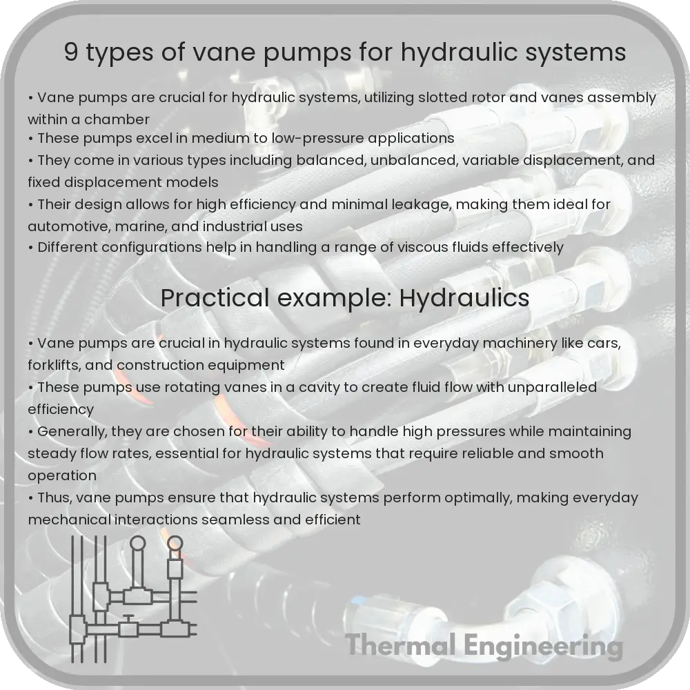
9 Types of Vane Pumps for Hydraulic Systems

Learn about vane pumps, essential for hydraulic systems, known for their efficiency and diverse applications in various industries.

9 Types of Vane Pumps for Hydraulic Systems

Understanding Vane Pumps in Hydraulic Systems

Vane pumps are a crucial component in hydraulic systems, known for their efficiency and reliability in transferring fluids at consistent pressures. They utilize retractable vanes that slide in and out of a rotor to create vacuum and compression. These pumps find extensive applications in automotive, industrial, and aerospace fields due to their adaptability in various viscosity ranges and their excellent performance in high-pressure environments. Below, we explore nine of the most common types of vane pumps used in hydraulic systems.

Types of Vane Pumps

Each type of vane pump offers distinct characteristics and benefits, making it suitable for specific applications. Here’s a closer look at each:

  1. Single Vane Pumps: These are the simplest form of vane pumps, featuring a single rotor with multiple vanes. They are used in lower pressure applications and are valued for their compact design and moderate flow rates.
  2. Double Vane Pumps: These pumps have two rotors that work simultaneously to increase the pump’s capacity and efficiency. Double vane pumps are excellent for applications requiring medium to high flow rates.
  3. Variable Displacement Vane Pumps: These allow the adjustment of the flow rate by changing the geometry of the pump, making them highly efficient for systems where load conditions frequently change.
  4. Balanced Vane Pumps: Balanced vane pumps are designed to minimize the load on pump bearings, leading to longer lifespan and higher efficiency, especially in high-pressure systems.
  5. Unbalanced Vane Pumps: These are more common and simpler than balanced pumps but tend to have higher wear and tear due to uneven distribution of hydraulic forces across the pump structure.
  6. Fixed Displacement Vane Pumps: As the name suggests, these pumps provide a constant flow rate and are often used in circuits that require a simple, durable, and cost-effective pumping solution.
  7. Multi-Stage Vane Pumps: These pumps use multiple rotors in series or parallel configurations to achieve higher pressures and greater flow rates, suitable for heavy-duty hydraulic applications.
  8. High Performance Vane Pumps: These are engineered for applications requiring extremely high pressures and efficiencies. They often feature advanced designs with enhanced bearing and sealing configurations.
  9. Eco-Friendly Vane Pumps: Developed with sustainability in mind, these pumps are designed to minimize energy consumption and environmental impact, suitable for applications in green technologies and systems.

Conclusion

Vane pumps are versatile and efficient solutions for hydraulic systems, catering to a wide range of pressures, flow rates, and applications. Understanding the different types of vane pumps helps in selecting the right pump for specific hydraulic needs, ensuring optimal performance and durability. Whether for automotive, industrial, or aerospace applications, the appropriate vane pump can significantly enhance system efficiency and reliability.

8 Types of Magnetic Drive Pumps for Leak-Free Operations

Learn about magnetic drive pumps, essential for leak-free operations in industries dealing with hazardous or corrosive liquids.

8 Types of Magnetic Drive Pumps for Leak-Free Operations

Understanding Magnetic Drive Pumps: 8 Key Types for Leak-Free Operations

Magnetic drive pumps, renowned for their ability to prevent leaks and efficiently handle hazardous or corrosive liquids, have become indispensable in industries ranging from chemical manufacturing to pharmaceuticals. These pumps utilize magnetic coupling that establishes a drive without any physical contact between the motor and the impeller, thus eliminating the need for a traditional seal. This design not only reduces the risk of leakage but also minimizes maintenance needs and enhances operational safety. Below, we explore eight types of magnetic drive pumps commonly used across various industries.

1. Centrifugal Magnetic Drive Pumps

Centrifugal magnetic drive pumps are the most widely used type. They operate on the principle of centrifugal force, converting rotational kinetic energy to hydrodynamic energy of the fluid flow. Ideal for transferring liquids in large volumes, these pumps are commonly used in water treatment, chemical processing, and heating, ventilation, and air conditioning (HVAC) systems.

2. Rotary Vane Magnetic Drive Pumps

Rotary vane pumps feature a series of vanes mounted on a rotor, which rotates inside a cavity. In magnetic versions, the magnetic assembly drives the rotor without direct contact, which eliminates leakage risks. These pumps are ideal for precision transfer of fluids at low to medium flow rates and high pressures.

3. Diaphragm Magnetic Drive Pumps

Diaphragm magnetic drive pumps use a diaphragm moved by magnets to create a variable volume chamber that draws in and expels fluid. They are particularly effective for handling hazardous chemicals as there is no seal or valve to leak. These pumps are highly valued in industries that need a high level of purity and leak prevention.

4. Gear Magnetic Drive Pumps

Gear pumps rely on the meshing of gears to pump fluid by displacement. Magnetic drive versions use magnetic couplings to transmit torque to the gears without physical contact. They are especially useful for pumping viscous liquids smoothly and efficiently at constant flow rates.

5. Screw Magnetic Drive Pumps

Screw pumps use one or several screws to move fluids along the screw axes. In the magnetic drive variant, these pumps offer precise flow control and high pressure with minimal risk of leakage, making them suitable for complex fluid handling applications in the oil and gas industry.

6. Peristaltic Magnetic Drive Pumps

Peristaltic pumps involve compressing and relaxing a flexible hose or tube to move liquids. The magnetic drive technology in these pumps helps in minimizing maintenance as there are no seals to wear out, and they provide gentle, accurate pumping capabilities, ideal for shear-sensitive materials like biological fluids.

7. Piston Magnetic Drive Pumps

Piston pumps operate by using one or more reciprocating pistons to transport liquids. The magnetic coupling in these pumps ensures a secure, sealed environment, reducing the chances of contaminants entering the pump and enhancing the safety of high-pressure operations.

8. Progressive Cavity Magnetic Drive Pumps

A progressive cavity pump features a single helical rotor that turns inside a double helical stator of a larger diameter, thus creating series of cavities that progress from suction to the discharge end. Magnetic drive variations provide reliable, leak-free operation, particularly beneficial in the environmental and food processing sectors.

Choosing the right type of magnetic drive pump depends on several factors, including fluid characteristics, flow rate requirement, pressure conditions, and the specific needs of the application. With their diverse range and adaptable designs, magnetic drive pumps continue to meet the demanding criteria of modern industrial operations while ensuring environmental compliance and operational safety.

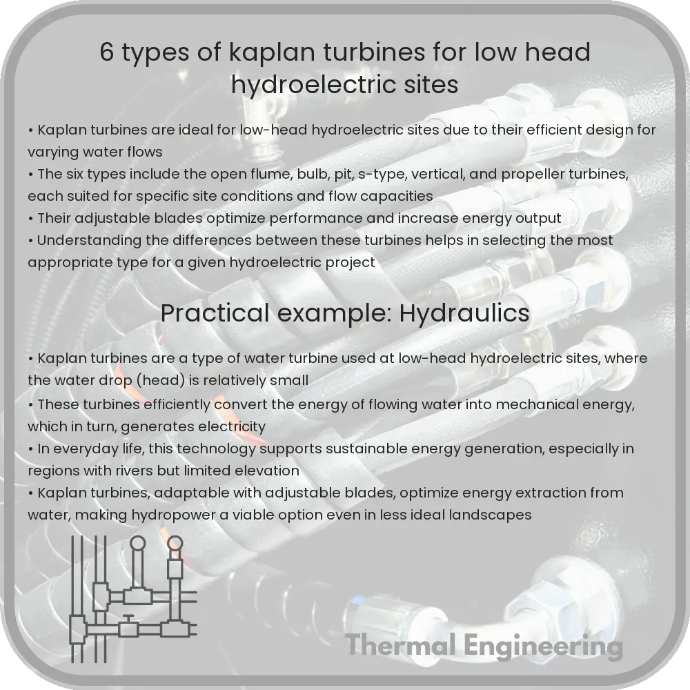
6 Types of Kaplan Turbines for Low-Head Hydroelectric Sites

Learn about Kaplan turbines, their types, and applications in low-head hydroelectric power generation.

6 Types of Kaplan Turbines for Low-Head Hydroelectric Sites

Understanding Kaplan Turbines: Types and Applications

Kaplan turbines, named after Austrian engineer Viktor Kaplan, are a type of water turbine used primarily for electrical power generation in low-head hydroelectric plants. Here, “low head” refers to the small height difference between the upper and lower water levels, typically less than 30 meters. Kaplan turbines are a subset of reaction turbines and are particularly efficient at handling high flow rates with variable heads due to their adjustable blades. This article explores six types of Kaplan turbines and their specific applications in low-head hydroelectric sites.

Types of Kaplan Turbines

  • Standard Kaplan Turbine: This is the most common form of Kaplan turbine. It features adjustable runner blades and a fixed wicket gate to regulate water flow. This design is highly efficient in converting low head but high flow water conditions into energy, making it ideal for river and small dam installations.
  • Propeller Turbine: Similar to the Kaplan but with fixed blades, the propeller turbine is typically used where the head and flow conditions remain relatively constant. While slightly less flexible than the fully adjustable Kaplan, it offers a simpler, more cost-effective solution for stable environments.
  • Tubular Turbine: These turbines are installed horizontally and feature a straight flow-through design, which helps to minimize the overall footprint of the power station. Tubular turbines are suitable for sites where space is limited and are often used in tidal and low-head storage pump stations.
  • Bulb Turbine: The bulb turbine incorporates the generator into a water-tight compartment at the nose of the turbine, improving accessibility and reducing the complexity of the power plant’s design. This type is particularly well-suited for low-head environments where a wide flow range must be accommodated.
  • Pit Turbine: Characterized by its vertical design and a gearbox that is located above the generator, pit turbines are advantageous where the water level fluctuates significantly. The vertical installation allows for easier maintenance and smaller civil works.
  • S-Turbine (Straflo): This turbine has a generator integrated around the circumference of the turbine. The unique layout helps in reducing the shaft length and hence, decreases mechanical losses. S-turbines are suitable for very low head sites and are recognized for their robustness and operational flexibility.

Conclusion

Kaplan turbines are a versatile and efficient choice for hydroelectric power generation, especially in low-head water sites. Knowing the specific characteristics and best uses of each type of Kaplan turbine allows engineers and project planners to select the most appropriate technology based on the environmental conditions and energy needs of a given location. Whether for large-scale hydro projects or smaller installations, understanding these options is crucial for optimizing power production and achieving sustainable energy goals.

Thus, Kaplan turbines continue to play a pivotal role in the rise of renewable energy technologies, providing a reliable and environmentally friendly energy source for future generations.

12 Types of Electric Motors for Automation and Drives

Exploring 12 common types of electric motors used in industrial automation and drive systems, detailing their unique characteristics and applications.

12 Types of Electric Motors for Automation and Drives

Understanding the Different Types of Electric Motors Used in Automation and Drives

Electric motors are crucial components in both industrial automation and various drive systems. They convert electrical energy into mechanical energy to perform tasks from small-scale applications like powering fans to large-scale industrial machinery. There are many types of electric motors, each with unique characteristics and suitable for specific applications. Here, we explore 12 common types of electric motors used in automation and drives.

1. AC Induction Motors

AC induction motors are among the most common motors used in industrial applications. They operate on alternating current (AC) and are noted for their high durability and efficiency. These motors work on the principle of electromagnetic induction, which involves generating electric current within a conductor placed in a changing magnetic field.

2. Synchronous Motors

Synchronous motors maintain a constant speed that is synchronized with the frequency of the supply current. They are perfect for applications where constant speed is necessary, such as in synchronous clocks, audio turntables, and conveyor belts.

3. Brushless DC Motors

Brushless DC (BLDC) motors operate electronically and have no brushes, reducing the need for maintenance. They offer high efficiency and excellent speed control and are commonly used in applications such as HVAC systems and computer hard drives.

4. Stepper Motors

Stepper motors move in discrete steps, making them ideal for applications requiring precise positioning such as 3D printers, CNC machines, and camera platforms. They can be controlled easily with digital signals, hence their extensive use in automation technologies.

5. Servo Motors

Servo motors provide precise control of angular or linear position, velocity, and acceleration. They are commonly used in robotic arms, machine tools, and antenna positioning systems among other applications where precise motion control is essential.

6. DC Compound Motors

A combination of series and shunt characteristics defines DC compound motors. They are used where higher starting torque and good speed regulation are required. These are found in automotive, lifting, and also in heavy-duty industrial applications.

7. Wound Rotor Motors

Also known as slip ring motors, wound rotor motors are used in applications requiring high starting torques or low starting currents. They feature a rotor with wire windings, and the rotor circuit can be connected through slip rings to external resistances for control purposes.

8. Permanent Magnet Motors

These motors use magnets to produce the motor’s magnetic field, eliminating the need for external field current. They offer improved efficiency and reliability, and are used in electric vehicles and renewable energy applications.

9. Gear Motors

Gear motors are integrated motors where the motor and the gearbox are combined into a single unit. This integrated setup helps in reducing the complexity of designing power and transmission systems, especially for tasks requiring high torque at low speeds.

10. Linear Motors

Unlike most electric motors which produce rotational motion, linear motors produce motion in a straight line. Common applications include maglev trains, automated machinery, and certain medical equipment.

11. Torque Motors

Torque motors are a type of high-performance servo motor that can provide a high torque output over a wide range of speeds, including stalled condition. They are used in applications such as robotics and automotive steering systems.

12. Switched Reluctance Motors

Switched reluctance motors have a simple and rugged construction and do not require permanent magnets. They operate by magnetically attracting the soft iron rotor to the stator poles, and are particularly used in applications where durability and reliability are critical, such as in aerospace and industrial machinery.

Each type of electric motor offers specific advantages and is suitable for certain applications based on requirements such as control, efficiency, and torque. Understanding these distinctions is vital for selecting the correct motor for automation or drive systems, ensuring optimal performance and efficiency in any engineering project.

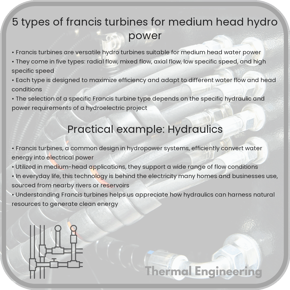
5 Types of Francis Turbines for Medium Head Hydro Power

Learn about the five types of Francis turbines designed for medium head hydro power, each optimized for specific site conditions and efficiency.

5 Types of Francis Turbines for Medium Head Hydro Power

Understanding the Variations: 5 Types of Francis Turbines for Medium Head Hydro Power

The Francis turbine is a type of reaction turbine, commonly used in hydroelectric power plants that operate at water heads from 40 meters to 600 meters. Named after James B. Francis who developed it in the 1840s, this turbine is versatile and efficient. Particularly for medium heads—typically considered to range between 100 meters and 400 meters—there are several adaptations of the Francis turbine that enhance its performance and suitability. Here, we explore five distinct types of Francis turbines utilized for medium head hydroelectric projects.

1. Spiral Case Francis Turbine

The Spiral Case Francis Turbine characteristically features a spiral-shaped casing that uniformly distributes water to the turbine runner. This design minimizes energy losses as water transitions from the high pressure of the penstock to the lower pressure environment of the turbine blades. The spiral casing is particularly effective in medium head applications where managing water flow and minimizing turbulence is crucial for maintaining efficiency.

2. Compact Francis Turbine

Designed for installations that require a smaller footprint, the Compact Francis Turbine is ideal for medium head sites with limited space. This variant maintains the efficiency and performance characteristics of traditional Francis turbines but in a configuration that reduces the overall size and complexity of the civil construction needed, thereby reducing costs as well.

3. High Flow Francis Turbine

In scenarios where the available water flow rate is exceptionally high, the High Flow Francis Turbine comes into play. This type is engineered to handle larger volumes of water without suffering from cavitation—a common problem where vapor bubbles form in low pressure regions, potentially damaging the turbine. By optimizing the shape and pitch of the blades, this turbine manages high flow rates effectively at medium heads.

4. Variable Speed Francis Turbine

With advancements in technology, Variable Speed Francis Turbines have become feasible and are increasingly used in medium head plants. Unlike conventional fixed speed turbines, these turbines can adjust their operating speed to match fluctuating water flow conditions, thereby maximizing efficiency and output across varying operational demands. This capability makes them highly adaptable and efficient in regions with significant seasonal variation in water availability.

5. High Efficiency Francis Turbine

Engineered to maximize energy conversion, the High Efficiency Francis Turbine incorporates refined blade geometries and materials that reduce friction and hydraulic losses. Especially suitable for medium head installations, this turbine variant ensures that a greater percentage of water’s kinetic and potential energy is converted into mechanical energy, leading to higher electrical output for the same amount of water compared to standard models.

In conclusion, while all Francis turbines operate on the same basic principles, their adaptations make them suitable for specific conditions encountered in medium head hydroelectric projects. By choosing an appropriate type of Francis turbine, engineering professionals can optimize the balance between cost, efficiency, and performance, effectively harnessing the power of water to generate electricity.