Facebook Instagram Youtube Twitter

7 Types of Axial Flow Pumps for Large Volume Transfer

Learn about axial flow pumps, their types, applications, and criteria for selection to enhance industrial fluid management.
7 Types of Axial Flow Pumps for Large Volume Transfer

Understanding Axial Flow Pumps: Types and Applications

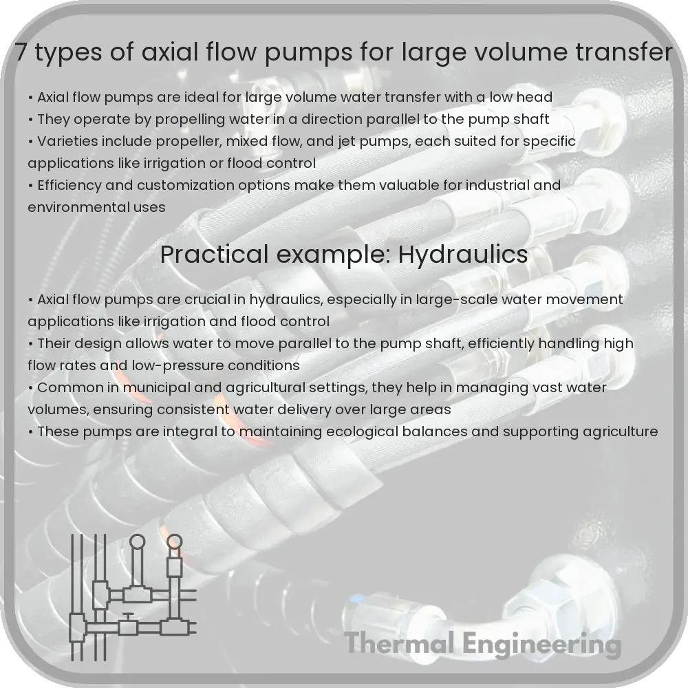
Axial flow pumps are a type of centrifugal pump that uses an impeller in a tube to move fluid in a direction parallel to the impeller shaft. They are designed for situations requiring large volumes of fluid to be moved across relatively low pressure heads. With their high flow rate capabilities, axial flow pumps are widely used in industries like agriculture for irrigation, flood control, and in municipal applications for water and wastewater management.

7 Types of Axial Flow Pumps

There are several configurations of axial flow pumps, each designed to meet specific needs in terms of volume, pressure, and installation requirements. Here are seven common types:

  • Tube Axial Pumps: These pumps have a propeller that is mounted in a tube. This design is suitable for moving large volumes of air or water at low pressures. They are commonly used in ventilation systems.
  • Propeller Pumps: Similar to tube axial pumps but used primarily for moving liquids. They have a propeller mounted directly to the drive shaft and are often used in applications involving water circulation, such as in aquaculture or cooling systems.
  • Pipe Axial Pumps: Integrated directly within a pipeline, these pumps help transport fluids without the need for a separate housing. They are ideal for pumping clean water in water supply systems.
  • Low Head Axial Pumps: These are optimized for applications where a high flow rate is needed but with minimal resistance or head. Commonly utilized in flood drainage or irrigation.
  • High Flow Axial Pumps: Designed to move exceptionally large volumes of fluid, these pumps are used in applications that require significant fluid management like large scale irrigation projects or water parks.
  • Vertical Axial Flow Pumps: These pumps are installed vertically, making them suitable for installation in deep pits or wells. They are primarily utilized for water extraction and in sump applications.
  • Submersible Axial Flow Pumps: Capable of operating while submerged in the fluid they are pumping, these pumps are commonly used for drainage and sewage handling in deep water installations.

Criteria for Selecting an Axial Flow Pump

Selecting the right axial flow pump involves considering multiple factors:

  • Flow Rate: The quantity of fluid that needs to be moved per unit of time, measured in cubic meters per second or gallons per minute.
  • Head: The total hydraulic energy per unit volume of fluid, largely dependent on the changes in speed and pressure as the fluid moves through the pump.
  • Fluid Characteristics: The type of fluid (water, sewage, chemicals, etc.), including its viscosity and whether it contains solids, which impacts the choice of pump material and design.
  • Energy Efficiency: Particularly important in applications where pumps operate continuously, as the operational cost can be impacted heavily by energy usage.
  • Installation Space: Some axial flow pumps, like vertical models, require specific spatial configurations for installation.

Conclusion

Axial flow pumps are vital in handling large volume fluid transfer across various industries. By understanding the different types of axial flow pumps and their specific advantages, users can select the best type based on their unique requirements, ensuring efficient and effective operations.
9 Types of Gear Pumps for High Viscosity Fluids

Learn how gear pumps effectively handle high-viscosity fluids like oils and paints, exploring their types, applications, and operational principles.

9 Types of Gear Pumps for High Viscosity Fluids

Understanding Gear Pumps for High Viscosity Fluids

Gear pumps are a type of positive displacement pump, which means they move a fixed amount of fluid for each cycle of operation. They are especially effective for pumping high viscosity fluids, such as oils, paints, and syrups, because of their ability to handle thick substances without a loss of efficiency. There are various types of gear pumps, each designed to meet specific demands of pressure, viscosity, and maintenance.

Types of Gear Pumps

Here, we explore nine common types of gear pumps used in handling high viscosity fluids:

  1. External Gear Pumps: These are the most common type of gear pumps, consisting of two identical gears that rotate against each other in a tightly fitted casing. The liquid is moved around the casing by the gears, from the inlet to the outlet. External gear pumps are widely used because they are simple, versatile, and relatively inexpensive.
  2. Internal Gear Pumps: With internal gear pumps, one of the gears is external and the other is an internal ring gear. This type provides smoother flow than external gear pumps and a better handle on higher viscosity fluids.
  3. Lobe Pumps: Technically not a gear pump, but operating under a similar principle with lobed gears (usually two or three) rotating synchronously via external timing gears. Lobe pumps are excellent for handling viscous fluids without damaging any solids present in the fluid.
  4. Helical Gear Pumps: These pumps feature gears with helical teeth which engage more gradually and smoothly than straight teeth, resulting in less pulsation and quieter operation. Ideal for applications requiring smooth, constant flow and high pressures.
  5. Spur Gear Pumps: Utilizing straight-toothed gears, spur gear pumps are a common form for applications where noise is not a concern, and high-viscosity fluid needs to be pumped at a constant rate.
  6. Gerotor Pumps: Gerotor pumps use an internal gear (rotor) and a non-circular outer gear (stator). They are particularly effective for high-viscosity fluids and provide excellent suction capabilities.
  7. Screw Pumps: Screw pumps use two or more screws, which mesh together and rotate within a cylindrical cavity. These pumps handle high viscosity fluids very well with a low noise level and a strong capability for high pressures.
  8. Peristaltic Pumps: While not a gear pump in the standard sense, peristaltic pumps compress a flexible tube to move the fluid. This method is gentle and can handle delicate or viscous fluids without contaminating the pump mechanisms.
  9. Progressive Cavity Pumps: Another alternative type, progressive cavity pumps consist of a helical rotor that moves eccentrically in a helical stator. This design is highly effective for handling very high-viscosity fluids and is also used for dosing and metering applications.

Applications of Gear Pumps in Industry

Gear pumps are essential in numerous industrial applications. In the food and beverage industry, they are used to pump thick sauces, creams, and syrups. The chemical industry uses them to handle viscous chemicals safely. In manufacturing, gear pumps are crucial for moving viscous lubricants, paints, and adhesives.

Conclusion

Gear pumps, in their various forms, play an essential role in handling high-viscosity fluids across diverse industries. Each type has specific strengths making it suitable for particular tasks and environments. Understanding these distinctions helps in choosing the right gear pump for specific industrial needs, ensuring efficacy, efficiency, and longevity in operations.

12 Types of Wind Turbines for Renewable Energy Production

Explore 12 common types of wind turbines used in renewable energy production, detailing their unique designs and applications.

12 Types of Wind Turbines for Renewable Energy Production

12 Types of Wind Turbines for Renewable Energy Production

Wind turbines are a cornerstone of renewable energy production, harnessing the natural power of the wind to generate electricity. There are several types of wind turbines, each with unique characteristics and suitable for different environments. Below, we explore 12 common types of wind turbines used in the field of renewable energy.

1. Horizontal-Axis Wind Turbines (HAWTs)

The most common type of wind turbine is the Horizontal-Axis Wind Turbine (HAWT). These turbines have a main rotor shaft and electrical generator at the top of a tower, and must be pointed into the wind. They typically have two or three blades and operate efficiently in high-wind conditions.

2. Vertical-Axis Wind Turbines (VAWTs)

Vertical-Axis Wind Turbines (VAWTs) have a vertically oriented rotor shaft. The two primary designs in this category are the Savonius and Darrieus models, which differ in blade design and rotational dynamics. VAWTs are advantageous in that they can capture wind from any direction.

3. Darrieus Wind Turbines

Named after its inventor Georges Darrieus, these turbines have a rotor with a shape akin to an egg beater. Darrieus turbines are a type of VAWT that is efficient but may require an external power source for starting.

4. Savonius Wind Turbines

Another type of VAWT, Savonius turbines feature rotor blades that are essentially scooped drums. These turbines prioritize torque over speed, making them useful in applications where high-starting torque is required.

5. Giromill Turbines

A subtype of Darrieus turbine, Giromill features straight, as opposed to curved, blades. These are simpler to construct and can operate in a narrower range of wind speeds.

6. Cycloturbines

Cycloturbines, also a variant of the Darrieus type, have adjustable blade pitch, which helps control rotational speed and maximize efficiency across varying wind conditions.

7. Hybrid Darrieus-Savonius Turbines

This design combines elements of both Darrieus and Savonius turbines to improve efficiency and torque. The Savonius components help start the turbine, and the Darrieus blades provide efficient energy conversion.

8. Offshore Wind Turbines

Offshore wind turbines are HAWTs specifically designed for installation in large bodies of water, where wind speeds are typically higher. These turbines can be much larger and generate more power.

9. Onshore Wind Turbines

Conventional onshore wind turbines are predominantly HAWTs. These turbines are installed in rural or remote land areas and are among the most visible forms of renewable energy infrastructure.

10. Ducted Rotor Turbines

These turbines feature a duct or shroud that helps to channel and accelerate wind onto the blades, increasing the turbine’s power output. This setup is particularly effective in lower wind speed areas.

11. Tethered Airborne Turbines

Tethered airborne turbines float high in the atmosphere, capturing energy from wind currents that are stronger and more consistent than those reached by traditional ground-based turbines. These systems are still largely in the experimental phase.

12. Portable Wind Turbines

As the name suggests, portable wind turbines are designed for easy transport and installation, making them ideal for temporary setups, rural areas, or emergency power needs. These types often utilize VAWT designs for their omnidirectional wind capture capabilities.

As the quest for cleaner and more sustainable energy sources continues, the technology behind wind turbines is constantly evolving, with new designs and innovations emerging regularly. Each type of wind turbine offers specific advantages, making them suitable for different applications and environments in the global effort to harness renewable energy.

3 Types of Diaphragm Pumps for Chemical Processing

Learn about diaphragm pumps used in chemical processing, covering types like air-operated, electric, and hydraulic models.

3 Types of Diaphragm Pumps for Chemical Processing

Understanding Diaphragm Pumps in Chemical Processing

Diaphragm pumps are a type of positive displacement pump used extensively in chemical processing for the transfer of fluids, including aggressive and corrosive chemicals. These pumps are prized for their reliability, efficiency, and ability to handle a variety of materials safely. Generally, diaphragm pumps operate by the flexing of a diaphragm back and forth, creating a vacuum that draws in and then expels fluids. Here, we explore three common types of diaphragm pumps used in chemical processing: air-operated, electrically operated, and hydraulic diaphragm pumps.

Air-Operated Diaphragm Pumps (AODPs)

Air-operated diaphragm pumps (AODPs) utilize compressed air as their power source, making them highly useful in hazardous or explosive environments. This type of pump is characterized by its simple design, absence of electrical components, and ease of maintenance.

  • Safety: AODPs are inherently safe for use in volatile environments due to the absence of electrical wiring or components that could generate sparks.
  • Versatility: They can handle a diverse range of fluids, including those with high viscosity or containing solid suspensions.
  • Cost-Effectiveness: With fewer moving parts compared to other pump types, AODPs typically have lower maintenance costs.

Electrically Operated Diaphragm Pumps

Unlike air-operated variants, electrically operated diaphragm pumps are powered by electric motors. These pumps are suitable for environments where compressed air is not available or for applications requiring more precise control over the pump operation.

  • Precision Control: Electric motors can be regulated using variable frequency drives (VFDs), which allow for precise control over the flow rate and pump speed.
  • Energy Efficiency: Electrically operated pumps can be more energy-efficient than air-operated alternatives, particularly in settings where electricity cost is lower than compressed air production.
  • Environmental Impact: These pumps produce less noise and have a smaller carbon footprint when sourced from renewable energy.

Hydraulic Diaphragm Pumps

Hydraulic diaphragm pumps are driven by hydraulic oil, which powers the diaphragm movement. This type of pump is typically used for high-pressure applications and offers enhanced durability and performance under strenuous conditions.

  • High-Pressure Capability: The hydraulic system enables these pumps to operate under higher pressures, ideal for moving fluids over long distances or against significant resistance.
  • Durability: Hydraulic pumps are robust and well-suited for continuous, heavy-duty operations.
  • Leak Prevention: These pumps often feature a double diaphragm design with a leakage detection system, which enhances safety when handling hazardous chemicals.

Choosing the right type of diaphragm pump for chemical processing depends largely on the specific requirements of the operation, including the type of chemicals being processed, the necessary flow rate, environmental conditions, and budget constraints. Understanding the unique benefits of air-operated, electrically operated, and hydraulic diaphragm pumps helps in selecting the most suitable option that ensures safety, efficiency, and reliability in any chemical processing application.

4 Types of Rocket Engines for Space Exploration

An in-depth exploration of the types and mechanics of rocket engines used in space exploration, highlighting their unique features and applications.

4 Types of Rocket Engines for Space Exploration

Introduction to Rocket Engines

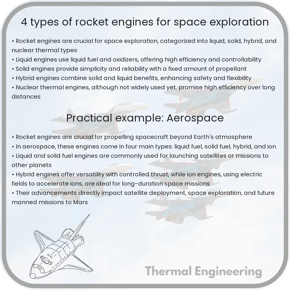
Rocket engines are the powerhouse behind space exploration. They are designed to propel spacecraft beyond the confines of Earth’s atmosphere. Different types of rocket engines are used depending on the mission requirements, such as payload size, destination, and journey duration. Here, we explore four primary types of rocket engines that have propelled various missions through space.

1. Liquid Propellant Rocket Engines (LREs)

Liquid Propellant Rocket Engines use liquid fuel and oxidizer stored in separate tanks. When needed for combustion, the two components are pumped into a combustion chamber where they mix and ignite. The key advantage of LREs is their throttleability which allows for precise control of the engine’s thrust during flight, making them suitable for manned missions and delicate orbital maneuvers.

  • Fuel Types: Commonly used fuels include liquid hydrogen or kerosene, while the oxidizer is often liquid oxygen.
  • Examples: The Space Shuttle’s main engines and the engines used on the Falcon 9 by SpaceX utilize this technology.

2. Solid Rocket Motors (SRMs)

Solid Rocket Motors use a different approach, with fuel and oxidizer mixed together in a solid form. Once ignited, the reaction continues until all propellant is exhausted. SRMs are known for their simplicity and reliability, offering high thrust but without the ability to throttle or shut down once ignited.

  • Usage: Often used as boosters for space shuttles or other rockets needing additional thrust during launch.
  • Examples: The Space Shuttle’s solid rocket boosters are prime examples of SRMs in action.

3. Hybrid Rocket Engines

Hybrid Rocket Engines combine aspects of solid and liquid rocket technologies. They use a solid fuel source along with a liquid or gaseous oxidizer. The oxidizer is stored in a tank and injected into the combustion chamber containing the solid fuel to control the rate of reaction.

  • Advantage: They offer more control than SRMs due to the throttleable nature of the oxidizer flow and are safer to handle before ignition.
  • Examples: Virgin Galactic’s SpaceShipTwo uses a hybrid engine for suborbital flights.

4. Ion Thrusters

Ion Thrusters represent a category of non-chemical propulsion systems used primarily for in-space operations. These engines work by ejecting charged particles (ions) at high speeds to create thrust. Although they provide much lower thrust compared to chemical rockets, their efficiency is remarkably high, allowing spacecraft to carry less propellant for longer missions.

  • Mechanism: Typically, xenon gas is ionized, then accelerated by electric fields to high speeds.
  • Applications: Used primarily for fine-tuning the orbits of satellites or for deep-space probes on long-duration missions, such as the Dawn spacecraft.

Conclusion

The type of rocket engine selected for a space mission dramatically impacts the mission’s design and capabilities. From the powerful, immediate thrust of solid rocket motors to the sustained, efficient drive of ion thrusters, engineers must consider the specific needs of the mission to select the appropriate technology. As space exploration evolves, so too will the technologies driving us beyond our planetary bounds.

Heat exchanger fouling prevention

Learn about heat exchanger fouling, its causes like biological, chemical, and particulate deposits, and effective prevention strategies.

Heat exchanger fouling prevention

Understanding and Preventing Heat Exchanger Fouling

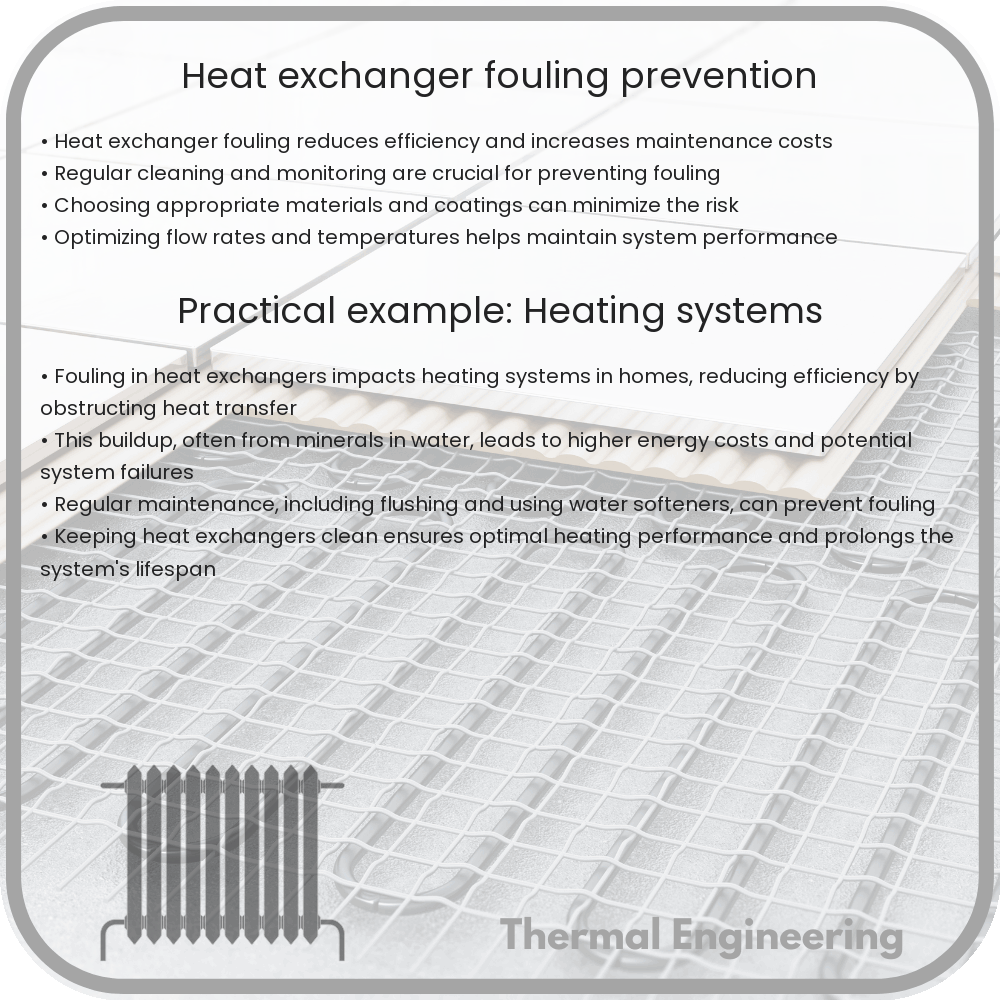
Heat exchangers are critical components in industrial, residential, and environmental systems, facilitating the transfer of heat between two or more fluids. However, the efficiency of heat exchangers can be severely compromised by a common issue known as fouling. Fouling refers to the accumulation of unwanted materials on the heat transfer surfaces, which can lead to reduced heat transfer, increased energy consumption, and potential equipment failure. In this article, we will explore the causes of heat exchanger fouling and discuss strategies to prevent it.

Causes of Heat Exchanger Fouling

Fouling in heat exchangers can occur due to various reasons, each associated with the type of substances involved and operational conditions. Some common causes include:

  • Biological fouling: Accumulation of microorganisms, plants, algae, or biofilms that can thrive in certain temperatures and nutrient-rich environments.
  • Chemical fouling: Formation of deposits from chemical reactions, typically occurring in boilers, evaporators, or coolers where temperature changes are significant.
  • Particulate fouling: Caused by particles suspended in the fluids, which settle out on the heat transfer surfaces due to insufficient velocity or turbulence to keep them suspended.
  • Corrosion fouling: Results from chemical reactions between the heat transfer surface and the fluid, leading to corrosion products building up on the surface.

Strategies for Preventing Heat Exchanger Fouling

Effective measures to prevent fouling are essential for maintaining the efficiency, reliability, and longevity of heat exchangers. Some practical strategies include:

  • Proper Material Selection: Choosing appropriate materials for both the heat exchanger and the fluids involved can significantly reduce corrosion and chemical fouling.
  • Control of Fluid Velocity: Maintaining optimal fluid velocity helps minimize particulate and biological fouling by reducing sedimentation and discouraging biofilm formation.
  • Temperature Control: Regulating the temperature within specific limits can prevent the chemical reactions that lead to fouling.
  • Chemical Treatment: Adding inhibitors or biocides to the fluids can control chemical and biological fouling.
  • Regular Cleaning and Maintenance: Scheduled cleaning and maintenance are crucial to remove fouling deposits before they accumulate and lead to severe blockages or damages.
  • Fouling Resistant Design: Designing heat exchangers with features such as corrugated plates or enhanced surface coatings can reduce the surface area available for fouling and ease cleaning efforts.

Conclusion

Fouling in heat exchangers is a pervasive issue that can degrade the performance and efficiency of heat transfer processes. By understanding the causes of fouling and implementing effective prevention strategies, operators can significantly enhance the operational stability and economic performance of heat exchangers. Regular monitoring and maintenance aligned with the right material and design choices form a comprehensive approach to managing fouling in heat exchanger systems.

This knowledge serves as a foundation for industries relying on heat exchangers, ensuring that these critical components continue to operate efficiently and reliably in various applications.

Heat transfer in magnetic refrigeration

Learn about heat transfer in magnetic refrigeration, focusing on the magnetocaloric effect and its application in cooling technology.

Heat transfer in magnetic refrigeration

Understanding Heat Transfer in Magnetic Refrigeration

Magnetic refrigeration is a cooling technology based on the magnetocaloric effect (MCE). This phenomenon involves the heating and cooling of magnetic materials through the application and removal of a magnetic field. The process of magnetic refrigeration offers a potential energy-efficient and environmentally friendly alternative to conventional gas-compression refrigerators. In this article, we will explore the fundamentals of heat transfer in this innovative technology.

Basic Principles of Magnetic Refrigeration

The magnetocaloric effect is at the heart of magnetic refrigeration. When a magnetic material is placed in a magnetic field, it heats up; when the magnetic field is removed, the material cools down. This effect is due to the change in the magnetic entropy and the corresponding alignment of magnetic dipoles in the material. To exploit the MCE for refrigeration, the system typically undergoes a cycle comprising four main stages: magnetization, heat rejection, demagnetization, and heat absorption.

Key Stages of the Refrigeration Cycle

  1. Magnetization: A magnetic field is applied to the magnetocaloric material, causing it to heat up. The increase in temperature is due to the alignment of the magnetic spins.
  2. Heat Rejection: In this stage, the heat generated during magnetization is transferred to a heat transfer fluid, usually water or air, and rejected to the environment. Here, floating heat exchangers or active magnetic regenerators are commonly used.
  3. Demagnetization: The magnetic field is removed, allowing the magnetocaloric material to cool below its initial temperature due to the disorder among the magnetic spins.
  4. Heat Absorption: The now-cooled material absorbs heat from the refrigerated space, thereby lowering its temperature. This stage completes the refrigeration cycle.

Heat Transfer Mechanisms

Heat transfer in magnetic refrigeration primarily involves two mechanisms: convection and conduction. In fluid-based systems, convection plays a major role, with the heat transfer fluid circulating around the magnetocaloric materials to distribute thermal energy. Conduction is more significant within the solid structures of the refrigerator, particularly between heat exchangers and magnetocaloric materials.

Challenges and Efficiency Factors

One of the main challenges in optimizing heat transfer in magnetic refrigeration lies in the design of effective heat exchangers and magnetic field sources. The efficiency of a magnetic refrigerator is largely determined by the thermal and magnetic properties of the magnetocaloric materials used, as well as the strength and configuration of the applied magnetic field.

  • Material Properties: Materials with a large magnetocaloric effect typically exhibit more considerable temperature changes and can offer more efficient cooling.
  • Magnetic Field Strength: The intensity of the applied magnetic field directly impacts the extent of the temperature change in the magnetocaloric materials.
  • System Design: The overall design of the system, including how efficiently it can cycle through its magnetization and demagnetization stages, affects performance.

Magnetic refrigeration presents a promising future in the realm of cooling technologies. As research continues to enhance the efficiency of magnetocaloric materials and system designs, we can expect further improvements in how heat is transferred in these innovative systems, leading to broader adoption and environmental benefits.

10 Types of Hydraulic Turbines for Hydroelectric Power

Comprehensive guide to hydraulic turbines detailing various types including Pelton Wheel, Francis, Kaplan, and more for hydroelectric power generation.

10 Types of Hydraulic Turbines for Hydroelectric Power

Introduction to Hydraulic Turbines

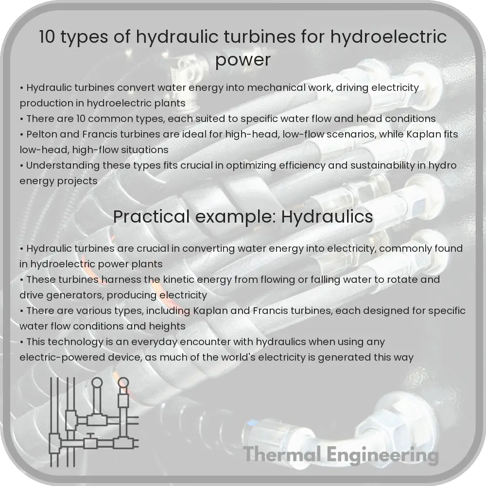
Hydraulic turbines are prime movers that convert the energy of flowing water into mechanical work, a fundamental transformation exploited in the generation of hydroelectric power. These turbines harness the kinetic and potential energy of water, which is then converted into electricity through generators. Varying in design and application, each type of hydraulic turbine serves a specific purpose depending on water flow, hydraulic head, and power needs. Here, we explore 10 common types of hydraulic turbines used in hydroelectric power stations.

Pelton Wheel

The Pelton wheel is an impulse turbine, primarily utilized in high-head, low-flow water conditions. It consists of spoon-shaped buckets mounted on the wheel’s edge, designed to capture water jets shot from a nozzle. The impact of the water creates a force that turns the wheel, making it highly efficient in settings with substantial height differences.

Francis Turbine

Developed by James B. Francis, the Francis turbine is a reaction turbine suitable for a wide range of head and flow conditions. It features a radial inflow design where water enters the turbine radially and exits axially through the runner. This flexibility makes it the most commonly used turbine in the world for hydroelectric power generation.

Kaplan Turbine

The Kaplan turbine is an axial flow reaction turbine, perfect for locations with low head and high flow. Its main characteristic is the adjustable blades, which can be optimized according to varying water conditions, thereby maintaining efficiency. It is particularly useful in river and run-of-river hydropower developments.

Turgo Turbine

A modification of the Pelton wheel, the Turgo turbine is another type of impulse turbine. It directs water jet at an angle on the runner, allowing it to handle more flow at a lower head compared to the Pelton wheel. This turbine is more compact and often preferred in medium head hydro sites.

Crossflow (Banki-Michell) Turbine

The Crossflow turbine, also known as a Banki-Michell turbine, features a simple design where water flows through a rectangular section runner twice. This unique design offers good efficiency across a range of head and flow conditions, and its simplicity makes it suitable for small scale and community-based hydro projects.

Bulb Turbine

The Bulb turbine integrates the generator into a waterproof casing in the water stream, often seen in tidal and low-head river applications. The placement allows direct drive without extensive gearing, thereby minimizing energy losses associated with mechanical transmissions.

Straflo Turbine

The Straflo turbine incorporates the generator around the periphery of the turbine’s runner. This arrangement facilitates a direct connection between the generator and the turbine, enhancing the unit’s overall compactness and efficiency, ideal for low-head hydroelectric plants.

Tubular Turbine

Designed for very low head hydroelectric projects, the Tubular turbine features a straight flow-through design, which enables the water to pass linearly through the turbine. These turbines are often used in tidal and wave power plants.

Pit Turbine

Characterized by its vertical design, the Pit turbine saves a significant amount of space, making it suitable for small locations. It is typically used in low to medium head applications and integrates well within existing dam structures without requiring extensive modifications.

Diagonal Turbine

Also known as an inclined flow turbine, the Diagonal turbine works under a variety of head conditions but is especially efficient in low to medium head and high flow situations. Its design allows water to flow diagonally to the axis of rotation, providing a compact solution with fewer cavitation issues.

Conclusion

Hydraulic turbines are a cornerstone of hydroelectric power generation, showcasing a variety of designs tailored to different environmental and operational requirements. Understanding the specific characteristics and suitable applications of each turbine type helps engineers and energy developers select the most appropriate technology for maximizing energy generation while considering environmental and geographical constraints.

6 Types of Positive Displacement Pumps in Fluid Transfer

Learn about positive displacement pumps and their essential role in precise fluid handling across various industries.

6 Types of Positive Displacement Pumps in Fluid Transfer

Understanding Positive Displacement Pumps in Fluid Transfer

Positive displacement pumps play a crucial role in various industries by allowing precise fluid handling and management. These pumps function by trapping a fixed amount of fluid then forcing (displacing) that volume into the discharge pipe. This results in a consistent flow regardless of the discharge pressure, making them ideal for applications requiring stable fluid flow. Below are six common types of positive displacement pumps used extensively in fluid transfer operations.

1. Gear Pumps

Gear pumps are a type of rotary positive displacement pump, consisting of two or more gears with interlocking teeth. The fluid is carried around the periphery by the gears and transported from the inlet to the outlet side of the pump. This design allows gear pumps to handle viscous fluids efficiently. They are commonly used in chemical installations, petrochemical sectors, and for hydraulic power applications.

2. Diaphragm Pumps

Diaphragm pumps use a flexible diaphragm that moves back and forth to create a temporary chamber to draw in and expel fluid. They are particularly effective for handling hazardous, corrosive, or high-purity fluids because the pump’s mechanics can be completely isolated from the fluid. Diaphragm pumps are widely used in industries such as water treatment, pharmaceuticals, and the food and beverage sector.

3. Screw Pumps

Screw pumps use one or several screws to move fluids along the screw axis. In a single screw pump, also known as a progressive cavity pump, a single screw rotates within a cylindrical cavity. For multiple screw pumps, two or three screws interlock to push the fluid through the pump. Screw pumps handle fluids gently and are used in applications requiring delicate handling such as in the food industry or waste water management.

4. Lobe Pumps

Lobe pumps are similar to gear pumps but use lobed rotors instead of gears. The rotors rotate without making contact, driven by external timing gears to ensure synchronization. Lobe pumps are highly sanitary and used often in pharmaceutical manufacturing, biotechnology, and food processing where contamination must be minimized.

5. Peristaltic Pumps

Peristaltic pumps, or tube pumps, operate by compressing and releasing a length of hose or tube, drawing fluid in with each squeeze. They are unique in that the fluid only touches the tube, hence reducing the risk of cross-contamination. This feature makes peristaltic pumps suitable for sterile applications such as in medical or laboratory environments.

6. Piston Pumps

Piston pumps utilize a piston moving forwards and backwards in a cylinder to draw in and expel fluid. They can handle high pressure and high viscosity fluids and are used in industries such as oil and gas, paint, and mining. Piston pumps can be designed to handle large flow rates and pressures, and can be either double-acting or single-acting.

Each type of positive displacement pump has its unique set of advantages and is suitable for different applications. Understanding the operational principles and suitability of each pump can help in selecting the right pump for specific industrial needs.

7 Types of Steam Turbines for Power Generation

Learn about the types and functions of steam turbines used in power generation, focusing on their design, efficiency, and applications.

7 Types of Steam Turbines for Power Generation

Introduction to Steam Turbines for Power Generation

Steam turbines are a critical component in the power generation industry, converting thermal energy from steam into mechanical energy that drives generators to produce electricity. These devices harness the principles of thermodynamics and fluid dynamics to efficiently produce power in various settings, including utility-scale power plants and industrial facilities. Different types of steam turbines are designed to accommodate a range of operational needs and efficiencies. This article explores seven common types of steam turbines used in power generation.

1. Impulse Steam Turbine

The impulse steam turbine leverages the kinetic energy of high-velocity steam jets to turn the turbine blades. The steam is expanded, and its velocity is increased through a nozzle before it strikes the blades of the rotor. Impulse turbines are characterized by their simple design and are most effective at handling high pressure and low mass flow rates of steam.

2. Reaction Steam Turbine

In reaction turbines, both the rotor and the stator blades are designed to expand the steam. Unlike impulse turbines, where energy transfer occurs mainly at the stator, reaction turbines involve the expansion of steam in both the fixed and moving blades, thereby producing thrust as steam accelerates through the turbine stages. This type of turbine is generally more efficient than the impulse turbine, especially at lower pressure drops and higher flow rates.

3. Condensing Steam Turbine

Condensing steam turbines are common in power plants where high efficiency is critical. In these turbines, the exhaust steam is condensed into water by cooling in a condenser after doing its work in the turbine. This process creates a significant pressure drop, enhancing the turbine’s efficiency by allowing extraction of the maximum amount of energy from the steam.

4. Non-Condensing (Back Pressure) Steam Turbine

Non-condensing or back pressure steam turbines do not condense the exhaust steam but instead exhaust it into the process or the atmosphere at a higher pressure. These are typically used when the exhaust steam is required for process applications, such as in sugar mills, chemical plants, or district heating systems.

5. Extraction Steam Turbine

Extraction turbines allow steam to be extracted from one or more stages, at different pressures and temperatures, for use in various industrial processes, or for heating purposes. This type of turbine can optimize the generation of both electric power and thermal energy, making it a cornerstone of cogeneration or combined heat and power (CHP) systems.

6. Induction Steam Turbine

Induction turbines are somewhat less common. They can intake additional steam at intermediate stages. This feature can be utilized to adjust the power output or to incorporate steam from different sources, enhancing the flexibility in operations and overall system efficiency.

7. Reheat Steam Turbine

Reheat steam turbines feature a system where steam exits a high-pressure turbine stage, is reheated in a boiler, and then re-enters a low-pressure turbine stage. This process increases the expansion ratio without exceeding the temperature limits of the turbine blades, thus maximizing efficiency and minimizing blade wear.

Conclusion

Understanding the different types of steam turbines and their unique characteristics and applications can help in selecting the right turbine for specific power generation needs. Each type offers distinct advantages in terms of efficiency, suitability for various operational conditions, and integration with industrial processes. With advancements in technology, the role of steam turbines continues to evolve, underscoring their importance in the global energy landscape.