Facebook Instagram Youtube Twitter

6 Types of Cooling Curves in Material Science

Learn about cooling curves in material science, a crucial tool for analyzing temperature changes and phase transitions in materials.

6 Types of Cooling Curves in Material Science

Understanding Cooling Curves in Material Science

Cooling curves are essential graphical representations in material science that illustrate how the temperature of a substance decreases over time as it loses heat. This tool is invaluable for understanding the properties of materials, phase transitions, and the kinetics of cooling processes. In material science, different materials exhibit distinct cooling behaviors, which can be broadly categorized into several types. Here we discuss six fundamental types of cooling curves frequently encountered in the study of material behavior.

1. Pure Metals

For pure metals, the cooling curve is characterized by a sharp plateau during the phase transition from liquid to solid, known as the melting point. This plateau indicates where the temperature remains constant despite continued heat loss, as the energy is used to change the phase rather than the temperature. The equations governing this phase change typically involve the balance of heat transfer and the latent heat of fusion:

  • q = m * Lf
  • Where q is the heat involved, m is the mass, and Lf is the latent heat of fusion.

2. Alloys

Alloys exhibit a more complex cooling curve than pure metals, typically showing a range of temperatures over which solidification occurs. This range, between the liquidus and solidus temperature, represents a mushy zone where the material is partially solid and partially liquid. The complexity of the cooling curve is due to the different components of the alloy solidifying at different temperatures.

3. Eutectic Systems

In eutectic systems, the cooling curve again shows a plateau, similar to that of pure metals, but at the eutectic point. At this point, the alloy components solidify simultaneously at a constant temperature, which is typically lower than the melting temperatures of the individual components. This results in a fine mixture of phases that generally enhances certain properties like strength and toughness.

4. Glasses

Glasses, such as silicates and some polymers, cool without a distinct phase change to a crystalline solid. Their cooling curves do not exhibit a sharp phase change plateau. Instead, they demonstrate a gradual decrease in temperature and viscosity. The transformation range, where the glass transition occurs, is denoted by a broad, rounded step in the cooling curve, indicative of the supercooled liquid transforming into an amorphous solid.

5. Polymers

Polymers can show various cooling curve profiles depending on their nature (thermoplastics or thermosets) and composition. Thermoplastics typically exhibit a significant drop when passing through the glass transition and melting temperatures. Thermosets, which cross-link during curing, might show an exothermic peak before cooling resumes, reflecting the heat generated by the chemical reactions occurring as they set.

6. Composite Materials

Cooling curves of composite materials present a combination of the characteristics seen in their individual components. These curves can be quite complex, reflecting the distinct and multiple phase changes, differing thermal conductivities, and heat capacities of the matrix and reinforcement materials. Analyzing these curves provides insights into the effective processing temperatures and the interactions between the components under cooling conditions.

Cooling curves are potent tools in material science, providing deep insights into the material properties and behaviors during cooling. Understanding these curves facilitates the design of better materials and optimization of processing conditions to achieve desired material characteristics.

10 Types of Pump Cavitation and Solutions

Learn about pump cavitation, its types, causes, and effective solutions to prevent damage and improve efficiency in pumping systems.

10 Types of Pump Cavitation and Solutions

Understanding Pump Cavitation: Types and Solutions

Cavitation in pumps is a common issue where vapor bubbles form in the liquid being pumped and collapse in an area of higher pressure, potentially causing damage, noise, and decreased efficiency. Understanding the different types of cavitation and their solutions is crucial for maintaining a functional pumping system. Here are ten types of pump cavitation along with their respective solutions.

Types of Pump Cavitation

  1. Suction Cavitation

This occurs when a pump is under low pressure or high vacuum conditions. It causes the liquid to vaporize at low pressure, forming bubbles that collapse when moved to higher pressure areas, potentially causing damage.

  • Solution: Ensure adequate suction head, reduce pump speed, or select a pump with a lower NPSHR (Net Positive Suction Head Required).
  1. Discharge Cavitation

Discharge cavitation happens when the pump discharge pressure is extremely high or when the discharge flow is restricted. It causes high velocity flow that leads to vapor bubble formation and subsequent collapse.

  • Solution: Adjust throttle valve to reduce pressure, resize the pump, or increase pipe diameter to decrease resistance.
  1. Vaporous Cavitation

A form where vapor bubbles form due to physical properties of the fluid including temperature and vapor pressure, independent of external factors.

  • Solution: Lower the fluid temperature, use a fluid with higher vapor pressure, or decrease the operating pressure within the pump.
  1. Air Ingestion Cavitation

Caused by air leaking into the pump, usually through the suction line, leading to cavitation as air bubbles are compressed and vaporized.

  • Solution: Check and secure all fittings and seals in the suction line and ensure the line is void of any air leaks.
  1. Fluid Viscosity Cavitation

Occurs in high-viscosity fluids where flow velocities are reduced such that pressure drop in certain areas leads to cavitation.

  • Solution: Choose a pump designed to handle high-viscosity fluids or increase the cross-sectional area of the pump passages to reduce fluid speed and shear rates.
  1. Thermodynamic Cavitation

Occurs due to the thermodynamic effects of compressible fluids undergoing pressure and temperature fluctuations.

  • Solution: Employ temperature control methods, improve the thermal design of the system, or execute proper thermodynamic analysis prior to selection and operation.
  1. Flow Turbulence Cavitation

Results from severe flow disturbances such as vortices or turbulent flow at high velocities, leading to localized pressure drops.

  • Solution: Optimize flow patterns within the system, redesigning impellers or using flow straighteners where necessary.
  1. Velocity Cavitation

Rapid change in liquid velocity causing pressure to drop below vapor pressure and form cavities.

  • Solution: Reduce the flow rate, redesign the pump casing or piping for better flow dynamics.
  1. Pressure Pulsation Cavitation

Caused by the pulsating pressure of some reciprocating pumps, creating alternating high and low pressures around parts like valve assemblies.

  • Solution: Install pulsation dampeners near the problem areas to even out the pressure variations.
  1. Combination Cavitation

A situation where two or more types of cavitation occur simultaneously due to complex system conditions.

  • Solution: Conduct a comprehensive system analysis to identify and address the various contributing factors to the cavitation.

Wrapping Up

Pump cavitation is a complex but manageable problem within fluid pumping systems. By identifying the specific type of cavitation affecting a pump system, tailored strategies can be applied to mitigate the issues effectively. Keeping the machine health in check and adhering to operational best practices are fundamental to preventing recurring problems associated with pump cavitation.

7 Types of Refrigeration Cycle Analysis Tools

Understand the crucial tools used in analyzing and optimizing refrigeration cycles across various applications.

7 Types of Refrigeration Cycle Analysis Tools

7 Types of Refrigeration Cycle Analysis Tools

The analysis of refrigeration cycles is crucial for designing and optimizing various cooling systems used in domestic, commercial, and industrial applications. Engineers use several tools to analyze and enhance the efficiency of refrigeration cycles. Here, we explore seven essential types of analytical tools utilized in the study of refrigeration cycles.

1. Pressure-Enthalpy (P-h) Diagrams

A Pressure-Enthalpy (P-h) diagram is a vital tool in understanding the thermodynamic properties and energy transfers within a refrigeration cycle. It graphically represents the relationship between the pressure and the enthalpy (total heat content) of the refrigerant at different stages of the refrigeration cycle, including evaporation and condensation processes.

2. Psychrometric Charts

Psychrometric charts are used primarily in the analysis of air conditioning systems, which are a type of refrigeration cycle. The chart illustrates properties of air-water vapor mixtures at various temperatures and humidity levels, enabling engineers to analyze the air conditioning processes effectively, including cooling, heating, humidification, and dehumidification.

3. Refrigerant Property Tables

Refrigerant property tables provide detailed information on the thermodynamic properties of various refrigerants. Engineers use these tables to calculate important parameters such as temperature, pressure, enthalpy, and entropy at different points in the refrigeration cycle. This information is crucial for the correct sizing of components and ensuring efficient operation.

4. Thermodynamic Cycle Simulators

Thermodynamic cycle simulators are advanced software tools that allow for the dynamic simulation of refrigeration cycles and other thermodynamic processes. These tools typically offer options to model various cycles, customize refrigerant properties, and simulate real-time operational conditions, thus providing a comprehensive analysis platform.

5. Energy Efficiency Calculators

Energy efficiency calculators are used to estimate the efficiency of refrigeration systems. They analyze input parameters like electricity consumption, heat extraction rates, and overall system configuration to compute performance metrics such as Coefficient of Performance (COP) and Energy Efficiency Ratio (EER).

6. Vibration Analysis Tools

Vibration analysis tools help in diagnosing and preventing mechanical issues within refrigeration systems, such as those in compressors or fans, by detecting abnormal vibrations early. These tools are essential for preventative maintenance and can significantly extend the life of refrigeration equipment.

7. Computational Fluid Dynamics (CFD) Software

Computational Fluid Dynamics (CFD) software is used to simulate fluid and gas flow within the refrigeration cycle. It helps engineers visualize and optimize the flow dynamics and heat transfer in various components of the system, such as condensers, evaporators, and air ducts.

In conclusion, these seven types of refrigeration cycle analysis tools are fundamental for engineers to design, analyze, and optimize refrigeration systems. By effectively utilizing these tools, they can improve system efficiency, enhance reliability, and reduce energy consumption, leading to better engineered cooling solutions.

8 Types of Water Cooling Methods in Industry

Understand the various industrial water cooling methods, their applications, and benefits, from cooling towers to dry coolers.

8 Types of Water Cooling Methods in Industry

8 Types of Water Cooling Methods in Industry

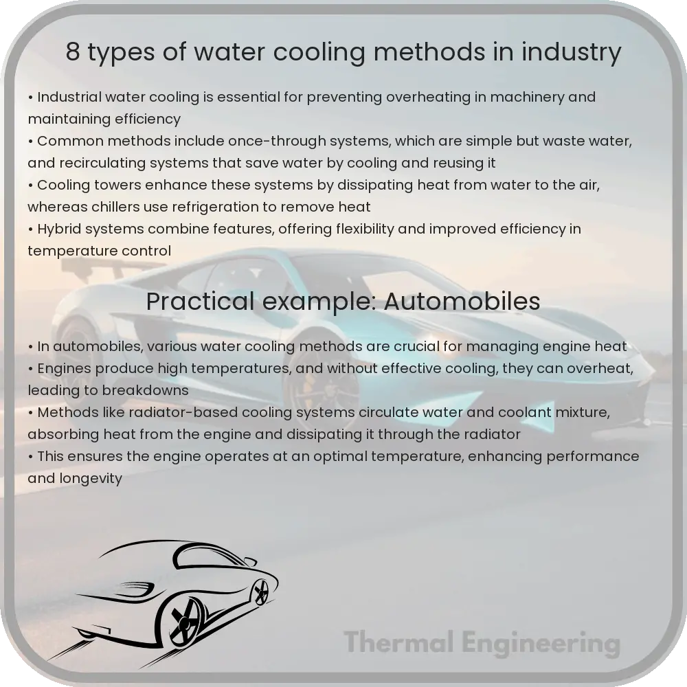
Water cooling is an essential part of many industrial processes, where control of temperature is crucial for efficiency and safety. Below are eight common water cooling methods used across various industries, each with specific advantages and applications.

1. Cooling Towers

Cooling towers are structures designed to cool water through direct contact with air. As hot water is sprayed into the tower, a part of the water evaporates, removing heat from the remaining water. Cooling towers are widely used in HVAC systems, power plants, and processing facilities.

2. Evaporative Condensers

Evaporative condensers combine the features of a condenser and a cooling tower. They use the evaporation of water to remove excess heat from a refrigerant gas. This method is particularly effective in space-saving as it combines two heat exchange processes.

3. Chilled Water Systems

Chilled water systems use refrigerant to cool down water to low temperatures. The chilled water is then circulated through a heat exchanger where it absorbs heat from the process load. This method is ideal for applications requiring stable and controlled temperatures.

4. Plate Heat Exchangers

Plate heat exchangers consist of corrugated plates assembled into a frame, creating a series of channels for hot and cold fluids to flow and exchange heat. This method offers high heat transfer efficiency and is commonly used in dairy, beverage, and chemical industries.

5. Shell and Tube Heat Exchangers

As the name suggests, these exchangers consist of a shell with a bundle of tubes inside. One fluid flows through the tubes while the other fluid flows outside the tubes but inside the shell. This design is versatile and widely used in petroleum refineries, chemical processes, and power stations.

6. Open Loop Systems

Open loop systems directly use river, lake, or sea water to absorb heat from industrial processes. After use, the water is returned to its source. While simple and cost-effective, this method can have environmental impacts and is dependent on local water availability.

7. Closed Loop Systems

In closed loop systems, cooling water is circulated within a contained system, not exposed to the external environment. This reduces water contamination and loss. Closed loops are typically used in situations where water conservation is important or where water quality cannot be compromised.

8. Dry Coolers

Dry coolers function similarly to air-cooled condensers, using air to remove heat from the water. Unlike cooling towers, no evaporation occurs, so water loss is minimal. Dry coolers are ideal for climates where water resources are scarce or in applications where water quality must be maintained.

Each of these water cooling methods offers specific advantages and may be preferred in different circumstances based on factors like environmental conditions, space availability, and energy efficiency requirements. Understanding these methods assists industry professionals in choosing the most appropriate cooling solution for their specific needs.

4 Types of Thermal Diffusivity Measurement Techniques

Learn about thermal diffusivity, a key property that describes how fast heat spreads through materials, influencing design in manufacturing and other industries.

4 Types of Thermal Diffusivity Measurement Techniques

Understanding Thermal Diffusivity Measurement Techniques

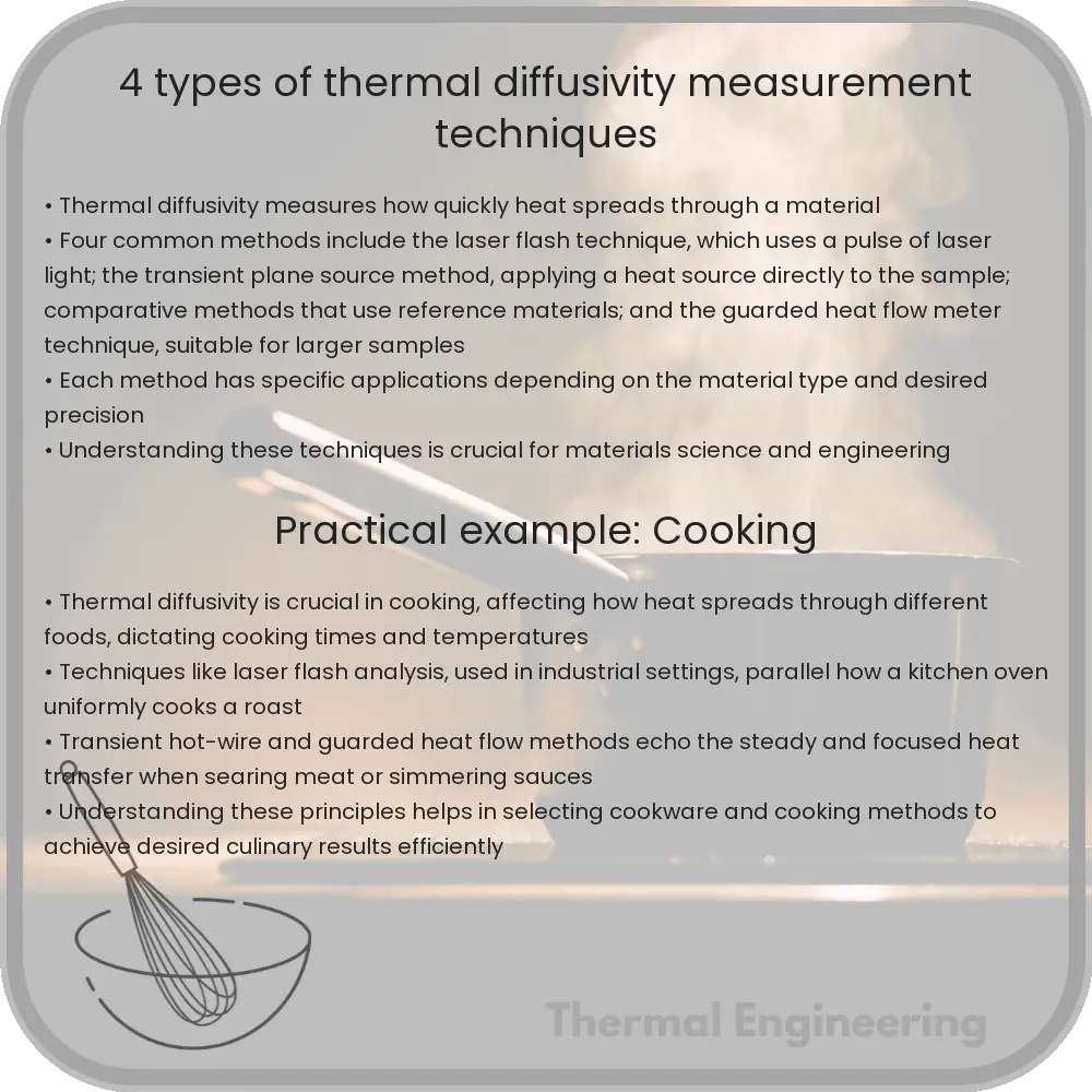
Thermal diffusivity is a critical property of materials that describes the rate at which heat spreads through a material. It combines thermal conductivity, density, and specific heat capacity into a single parameter, which is essential in fields such as manufacturing, construction, and electronics. Accurately measuring thermal diffusivity is crucial for predicting how materials behave under thermal stress and for designing materials with specific heat management properties. Here are four common techniques used to measure the thermal diffusivity of various materials.

1. Laser Flash Analysis (LFA)

Laser Flash Analysis is the most widely used method for measuring thermal diffusivity, especially for solids. In LFA, a short laser pulse heats the surface of a small sample disc. The increase in temperature on the opposite face of the disc is monitored using an infrared detector. The half-time (t1/2), the time it takes for the rear face temperature to reach half of its maximum value, is critical in determining the thermal diffusivity using the formula:

\[ D = \frac{0.1388 \times d^2}{t_{1/2}} \]

where D is the thermal diffusivity, d is the thickness of the sample, and \( t_{1/2} \) is the half-rise time. This technique is favored for its speed and its applicability to a wide range of temperatures.

2. Transient Plane Source (TPS)

The Transient Plane Source, also known as the “hot disk” method, involves a sensor that acts both as a heat source and as a temperature recorder. This sensor is sandwiched between two pieces of the sample material. When heat is applied, the sensor records the increase in temperature over time, which is then used to calculate the thermal diffusivity. The primary equation used in TPS is:

\[ D = \frac{\alpha}{C_p \times \rho} \]

where D is thermal diffusivity, \(\alpha\) is thermal conductivity, \(C_p\) is specific heat capacity, and \(\rho\) is density. The TPS technique is advantageous due to its ability to measure both anisotropic and isotropic materials and its non-destructive nature.

3. Transient Hot-Wire (THW) Method

In this method, a thin wire, usually made of platinum, acts as both the heat source and the temperature sensor. The wire is embedded within the material, and an electric current is passed through to heat it. The temperature increase is then monitored over time, and the thermal diffusivity is calculated based on the rate of temperature change in the material surrounding the wire. The thermal diffusivity is given by the relation:

\[ D = \frac{q}{4\pi \Delta T(t) \ln(t)} \]

where \( q \) is the power per unit length of the wire, \( \Delta T(t) \) is the change in temperature at time \( t \), and \( \ln(t) \) is the natural logarithm of the time. This method is suitable for fluids and high-conductivity materials.

4. Differential Scanning Calorimetry (DSC)

Differential Scanning Calorimetry measures how much heat is required to increase the temperature of a sample compared to a reference under controlled conditions. It allows for the determination of specific heat capacity, from which thermal diffusivity can be indirectly calculated using the formula:

\[ D = \frac{k}{\rho \times C_p} \]

Here, k is the thermal conductivity, \( \rho \) is the density, and \( C_p \) is the specific heat capacity of the material. DSC is particularly useful for polymers and other complex materials where specific heat capacities are important for understanding thermal behavior.

Each of these techniques has its own advantages and limitations and is suited to different types of materials and conditions. Understanding the nature of the material and the specific requirements of the application helps in selecting the most appropriate method for measuring thermal diffusivity.

9 Types of Temperature Control in Chemical Processes

Learn about the various temperature control methods used in chemical engineering to optimize safety, performance, and quality.

9 Types of Temperature Control in Chemical Processes

Understanding Types of Temperature Control in Chemical Processes

Temperature control in chemical processes is essential for maintaining safety, enhancing performance, and optimizing product quality. Precise temperature regulation influences reaction rates, product yields, and energy efficiency. Here are nine common types of temperature control methods employed in chemical engineering.

1. Feedback Control

Feedback control involves measuring the outlet temperature of a process and manipulating the input conditions to maintain the temperature at a desired set point. It reacts to changes in the system, like disturbances or load fluctuations. This is achieved by a controller which compares the actual temperature with the target temperature and adjusts inputs accordingly.

2. Feedforward Control

Feedforward control anticipates changes in temperature based on external variables such as reactant flow rates or ambient conditions. It adjusts the control variables in response to these measurements before they can affect the process, complementing the feedback mechanisms to enhance stability and response time.

3. On/Off Control

On/Off control is the simplest type of temperature control, where the heat source is either fully active or inactive. When the temperature drops below a specified threshold, the heating element is activated, and it is turned off once the temperature exceeds another threshold. This method is commonly used in smaller-scale or less critical applications.

4. Proportional Control

Proportional control reduces the discrepancy between the set point and the actual temperature by adjusting the control input in proportion to the error. This method avoids the instability that might be caused by on/off control but can still allow a small steady-state error.

5. Proportional-Integral Control (PI)

PI control combines proportional control with integral action, which accumulates past errors to completely eliminate the steady-state error. This increases system precision and stability, allowing quicker achievement of the temperature set point.

6. Proportional-Integral-Derivative Control (PID)

PID control is an extension of PI control that adds a derivative component. This considers the rate of change of the temperature, providing a predictive mechanism which further improves the control response. PID controllers are among the most widely used due to their effectiveness in a wide range of operating conditions.

7. Cascade Control

Cascade control uses two or more controllers in a series, where each controller handles different aspects of the process or different disturbances. For example, a primary controller may manage the set point of a secondary controller that directly controls the temperature. This hierarchy improves the response to disturbances and enhances overall control accuracy.

8. Ratio Control

Ratio control maintains specific ratios between variables, such as the flow rate of reactants and coolant, to enforce a desired temperature. This method is crucial in exothermic and endothermic reactions where maintaining the correct stoichiometric balance is essential for process stability and efficiency.

9. Adaptive Control

Adaptive control modifies its behaviors based on the process feedback to better handle complex, dynamic systems where process characteristics may change over time. This type of control is particularly useful in large-scale and multifaceted chemical processes where traditional control techniques may be insufficient.

Each of these temperature control methods offers unique advantages and is suitable for different types of chemical processes. The choice of method depends on factors such as the scale, complexity, required precision, and the specific characteristics of the process.

Understanding and implementing the appropriate temperature control strategy is critical for optimizing chemical process operations, ensuring safety, and reducing costs, emphasizing the vital integration of engineering principles in practical applications.

Heat transfer in electrochemical processes

Learn about the dynamics of heat transfer in electrochemical processes, crucial for enhancing device efficiency and safety in technologies like batteries and fuel cells.

Heat transfer in electrochemical processes

Understanding Heat Transfer in Electrochemical Processes

Heat transfer in electrochemical processes is a fascinating and crucial aspect of engineering that plays a significant role in the efficiency and safety of many modern technologies such as batteries, fuel cells, and corrosion prevention systems. This article breaks down the basics of heat transfer within these systems, why it matters, and how it is managed.

Basics of Heat Transfer in Electrochemical Processes

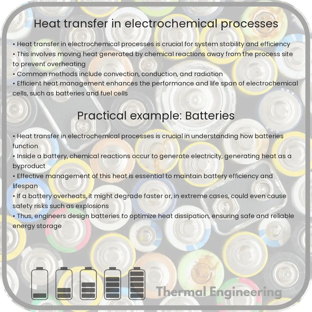
Electrochemical processes involve the conversion between chemical energy and electrical energy. These processes are typically exothermic or endothermic, meaning they either release or absorb heat. Heat transfer in these systems can affect the performance, efficiency, and lifespan of the devices in which these reactions occur.

There are three primary modes of heat transfer:

  • Conduction: Transfer of heat by direct molecular interaction. Within an electrochemical cell, heat conducts through the electrodes and the electrolyte.
  • Convection: Transfer of heat by the movement of fluids (which can be liquid or gas). In battery systems, this might involve the movement of electrolyte or air cooling systems.
  • Radiation: Transfer of heat in the form of electromagnetic waves. This form of heat transfer is generally less significant in electrochemical systems except at very high temperatures.

Heat Generation in Electrochemical Reactions

Electrochemical reactions involve the transfer of electrons at the electrode-electrolyte interface. These reactions can generate heat due to the following:

  1. Reaction Heat: Direct heat production or absorption during the electrochemical reaction (enthalpy change).
  2. Ohmic Heating: Heat generated by the resistance to the flow of electrons and ions through the materials which make up the cell (Joule heating). The heat generated can be estimated by the equation Q = I2R, where Q is the heat energy, I is the current, and R is the resistance.
  3. Overpotential Heating: Heat produced by the inefficiency in the electrodes when the actual voltage of the cell is higher than the theoretical voltage.

Thermal Management in Electrochemical Systems

Effective thermal management is crucial to maintain the performance and safety of electrochemical devices. Poor heat management can lead to reduced efficiency, battery degradation, or even hazardous conditions such as thermal runaway in batteries. Some common thermal management strategies include:

  • Heat sinks and cooling fins: These are often integrated into the design of the device to help dissipate heat through conduction and convection efficiently.
  • Thermal interface materials (TIM): These materials enhance heat conduction between hot spots and cooling devices.
  • Cooling systems: Liquid or air cooling systems can be used to manage extreme heat conditions, particularly in large battery packs or fuel cells.
  • Phase change materials (PCM): These materials absorb and release heat at specific temperatures to help regulate the temperature within the device.

Understanding the interplay of heat transfer and electrochemical processes is key to enhancing the design and functionality of many modern electrical devices. Engineers continually develop innovative solutions to handle the heat generated by electrochemical reactions, ensuring safety, stability, and performance enhancements in technologies such as renewable energy storage and electric vehicles.

By gaining a grasp of how heat is generated, transferred, and managed in these systems, both engineers and device users can improve efficiency and lifespan, contributing to more sustainable and robust energy solutions.

7 Types of Heat Sinks for Semiconductor Devices

Explore the various types of heat sinks used in semiconductor devices to manage heat and enhance performance.

7 Types of Heat Sinks for Semiconductor Devices

Understanding Heat Sinks in Semiconductor Devices

Heat sinks are critical components in managing the heat generated by semiconductor devices like CPUs, GPUs, and power transistors. These components ensure that the device operates within safe temperature limits, enhancing performance and extending lifespan. There are several types of heat sinks, each designed to meet specific requirements based on thermal performance, space, weight, and cost constraints. Here we explore seven common types of heat sinks used in electronic devices.

1. Stamped Heat Sinks

Stamped heat sinks are made by stamping thin sheets of metal, typically aluminum or copper, into a desired shape. They are cost-effective and suitable for low power applications where moderate cooling is sufficient. Stamped heat sinks are often used in consumer electronics where the economic efficiency of production is a priority.

2. Extruded Heat Sinks

Extruded heat sinks are among the most common and are manufactured by pushing heated metal (usually aluminum) through a die of the desired profile. This method allows for complex cross-sectional designs that improve heat dissipation. They are versatile and used in both low and high-power applications ranging from personal computers to industrial machinery.

3. Machined Heat Sinks

Machined heat sinks are created from a solid block of material (often aluminum or copper) using computer-controlled milling tools. This process is suitable for designs that require intricate detail and where high precision is necessary. Although more expensive, machined heat sinks are used in advanced electronics where maximum thermal conductivity and tailored geometries are needed.

4. Forged Heat Sinks

Forged heat sinks are made by compressing metal under high pressure to form a dense, high-strength product. The forging process can improve the thermal conductivity of the material due to its dense structure. These are typically used in rugged environments or in applications where mechanical stresses might occur alongside thermal stresses.

5. Bonded/Fabricated Heat Sinks

Bonded or fabricated heat sinks are constructed by attaching separate fins to a base using an adhesive or brazing. This type allows for a large surface area and therefore greater heat dissipation. They are particularly useful in custom or performance-sensitive applications, such as in power electronics and telecommunications equipment.

6. Pin Fin Heat Sinks

Pin fin heat sinks utilize an array of pin-like structures that extend from the base of the heat sink to increase the surface area for heat exchange. The increased surface area and the ability to orient the pins in various configurations make them effective in managing multidirectional air flow, enhancing their cooling capability.

7. Heat Pipes

While not a heat sink in the traditional sense, heat pipes are used in conjunction with heat sinks for high-performance cooling needs. They transfer heat from a hot component to a conventional heat sink, where it is dissipated into the surrounding environment. Heat pipes are particularly effective in tight spaces where direct air cooling is insufficient.

Conclusion

Selecting the right type of heat sink for a specific semiconductor device involves understanding both the thermal requirements of the device and the physical constraints of the application. Whether you’re designing for minimal noise, maximum efficiency, or cost effectiveness, there is a heat sink type suitable for every need in the vast landscape of electronic products.

5 Types of Aerodynamic Drag Reduction Strategies

Explore effective aerodynamic drag reduction strategies in engineering, enhancing vehicle performance and efficiency.

5 Types of Aerodynamic Drag Reduction Strategies

Understanding Aerodynamic Drag and Its Reduction Strategies

Aerodynamic drag is a force that opposes the motion of an object moving through air. It is an important factor in fields like automotive design, aerospace engineering, and even sports. Reducing drag can result in significant improvements in fuel efficiency, speed, and overall performance. Let’s explore five effective strategies used in engineering to reduce aerodynamic drag:

1. Streamlining

Streamlining involves shaping objects so that air flows more smoothly around them, which decreases the drag. This is commonly seen in the design of cars, airplanes, and even high-speed trains. Streamlined shapes are typically sleek and rounded, which allows air to pass over the surface with minimal resistance. For instance, the teardrop shape is a classic example of aerodynamic efficiency, often used as a model for high-performance vehicles.

2. Vortex Generators

Vortex generators are small, fin-like devices that can be attached to the surface of an object (like an aircraft wing or the roof of a car) to control air flow. They work by creating tiny vortices (spirals of air), which help maintain the flow of air close to the surface of the object. This process, known as “boundary layer control,” helps delay or prevent separation of the airflow from the object’s surface, thereby reducing the wake size and consequently, the drag.

3. Dimpled Surfaces

Inspired by golf ball technology, dimpled surfaces can also be used to reduce drag. The dimples work by promoting a turbulent boundary layer, which can stick to the object’s surface better than a laminar layer. This enhanced adherence reduces drag, especially at higher speeds. Dimpled surfaces are more commonly explored in sports equipment, but research continues into their potential applications in automotive and aerospace components.

4. Boundary Layer Suction

This technique involves suctioning off the slower-moving air near the surface (known as the boundary layer). By removing this layer, air resistance can be significantly reduced, lowering drag. Boundary layer suction typically requires a system of pores or slots on the surface through which the air is sucked away. While effective, the complexity and maintenance of such systems limit their popularity primarily to high-performance and experimental vehicles.

5. Tail Fairings and Boat Tails

Used extensively in the trucking industry, tail fairings, or boat tails, smooth the flow of air at the rear of vehicles. These devices extend the back of the vehicle and help in tapering the flow of air, minimizing the size of the wake. By effectively reducing the turbulence and vacuum that can occur at the back of large vehicles like trucks, these modifications enhance stability and reduce drag significantly.

Each of these strategies involves a fascinating application of physics to solve practical, real-world problems. By understanding and implementing such aerodynamic drag reduction techniques, engineers can dramatically improve the efficiency and performance of various vehicles and equipment, contributing to advancements in technology and environmental sustainability.

6 Types of Thermal Overload Protection for Motors

Learn about the essential role of thermal overload protection in preventing motor damage due to excessive heat from overcurrent.

6 Types of Thermal Overload Protection for Motors

Understanding Thermal Overload Protection for Motors

Thermal overload protection is crucial for the longevity and safety of electrical motors. It safeguards motors from the potential damage caused by excessive heat generated by overcurrent. This heat can result from various scenarios such as heavy loads, stalls, or operational inefficiencies. There are several types of thermal overload protection devices and systems, each designed to help prevent the overheating of motors. Here, we will explore six common types of thermal overload protections used in engineering.

1. Bimetallic Thermal Overload Relay

Bimetallic thermal overload relays involve two metals with different rates of thermal expansion bonded together. As the temperature increases due to excessive current, these metals expand at different rates, causing the bimetal strip to bend. This bending action eventually triggers a mechanism that breaks the circuit, thereby cutting off the power to the motor, preventing overheating. These relays are widely used due to their simplicity and cost-effectiveness.

2. Eutectic Alloy Thermal Overload Relay

Eutectic alloy thermal overload relays contain a eutectic alloy that melts at a specific temperature. In normal operation, a small heater heats an alloy pellet, keeping it solid. If an overload occurs, the temperature increases, causing the alloy to melt. The melting results in the release of a mechanism, generally a spring-loaded contact, which then opens the circuit to interrupt the current flow to the motor.

3. Electronic Thermal Overload Relay

Electronic thermal overload relays use microprocessors to monitor the motor’s current through sensors. The sensors provide real-time data to an electronic unit, which calculates the thermal capacity used and the remaining thermal capacity of the motor. When the heat exceeds a pre-set threshold, the system automatically cuts the power to avoid damage. This type of relay offers more precise control and is adaptable to various operating conditions.

4. Solid-State Relay with Thermal Protection

Solid-state relays (SSRs) with thermal protection incorporate electronic components to handle the switching operations without moving parts. They use sensors linked to a control unit that can accurately monitor the temperature and current. Upon detecting an overload, the control unit interrupts the power supply instantly, providing a faster response compared to mechanical systems.

5. Motor Thermal Protector (MTP)

Motor Thermal Protectors are built directly into the motor itself to provide localized thermal protection. These devices typically use temperature-sensitive conductive materials that change resistance dramatically at certain temperatures. This change is detected by the motor control circuitry, which then takes appropriate actions, such as shutting down the motor or altering its operational parameters to reduce the temperature.

6. Software-Based Motor Protection

Software-based motor protection techniques involve using software algorithms to predict potential overheating based on the analysis of current and other operational parameters. This predictive maintenance technology can be part of a more comprehensive motor management system, ensuring motors operate within their thermal limits through proactive adjustments and alerts. This type of protection is often used in conjunction with physical hardware for enhanced reliability.

In conclusion, thermal overload protection is a critical component in the management and maintenance of motors. Each type of thermal overload protection offers unique benefits and is suited to different situations and requirements. Choosing the right thermal overload protection depends on factors such as the motor size, application, environment, and specific operational demands. By adequately protecting motors from thermal overload, businesses can ensure reliable operation, reduce downtime, and extend the lifespan of their machinery.