Facebook Instagram Youtube Twitter

12 Types of Thermal Analysis Methods for Materials

Learn about the 12 types of thermal analysis methods used to study material properties as they change with temperature.
12 Types of Thermal Analysis Methods for Materials

Introduction to Thermal Analysis Methods

Thermal analysis is a branch of materials science where the properties of materials are studied as they change with temperature. Various methods of thermal analysis measure different aspects such as phase transitions, oxidation, and thermal stability. This article explores 12 types of thermal analysis methods commonly used to characterize material properties.

1. Differential Scanning Calorimetry (DSC)

Differential Scanning Calorimetry (DSC) measures how much heat is required to increase the temperature of a sample compared to a reference. It is widely used to analyze melting, crystallization, and specific heat capacity.

2. Thermogravimetric Analysis (TGA)

Thermogravimetric Analysis (TGA) measures the change in mass of a sample as it is heated or cooled. It is useful for studying materials’ thermal stability, decomposition, and compositional changes.

3. Differential Thermal Analysis (DTA)

Differential Thermal Analysis (DTA) involves heating or cooling a sample and a reference under identical conditions and observing any temperature differences. This technique helps detect phase transitions, such as melting and crystallization.

4. Thermomechanical Analysis (TMA)

Thermomechanical Analysis (TMA) measures the dimensional changes in a material as a function of temperature. It is used to study thermal expansion, softening, and glass transition temperature.

5. Dynamic Mechanical Analysis (DMA)

Dynamic Mechanical Analysis (DMA) measures the mechanical properties of materials as they are deformed under periodic stress. It provides insights into viscoelastic behavior, glass transitions, and softening points.

6. Dielectric Thermal Analysis (DETA)

Dielectric Thermal Analysis (DETA) analyzes the dielectric properties (dielectric constant and loss factor) of a material as a function of temperature and frequency. This method is crucial for investigating the behavior of polymers.

7. Thermally Stimulated Current (TSC)

Thermally Stimulated Current (TSC) measures the flow of electric current when a thermally insulated material is heated after being electrically polarized. TSC is used for studying charge trapping and release in materials.

8. Laser Flash Analysis (LFA)

Laser Flash Analysis (LFA) measures thermal diffusivity and conductivity. A pulse of a laser is applied to one side of a sample, and the temperature change on the opposite side is recorded to evaluate thermal properties.

9. Hot Disk Method

The Hot Disk Method involves placing a sensor between two sections of the sample material and passing an electric current through the sensor to raise the temperature. This test determines thermal conductivity and diffusivity.

10. Isothermal Titration Calorimetry (ITC)

Isothermal Titration Calorimetry (ITC) measures the heat released or absorbed during a chemical reaction at constant temperature. It is particularly useful in the study of binding interactions and energetics in biochemical processes.

11. Thermal Conductivity Meter

A Thermal Conductivity Meter directly measures a material’s ability to conduct heat. This method involves applying a known amount of heat to one side of the sample and measuring the temperature response.

12. Microscale Thermophoresis (MST)

Microscale Thermophoresis (MST) tracks the movement of molecules in temperature gradients to study molecular interactions, especially useful in pharmaceutical and biochemical research.

Conclusion

Understanding these thermal analysis methods helps in the selection of suitable materials for specific applications, contributing to advancements in various industries including aerospace, electronics, construction, and pharmaceuticals. Each method provides a different set of data invaluable for scientific and engineering decisions.

6 Types of Molten Salt Reactors and Their Advantages

Learn about Molten Salt Reactors, the types, advantages, and how they offer a safer, efficient alternative in nuclear technology.

6 Types of Molten Salt Reactors and Their Advantages

Understanding Molten Salt Reactors: Types and Advantages

Molten Salt Reactors (MSRs) are a type of nuclear reactor where the fuel is in a liquid state, typically dissolved in a mixture of molten fluoride or chloride salts. This technology stands out due to its high efficiency and safety features. MSRs operate at high temperatures but at atmospheric pressure, reducing the risk of explosions. There are several types of MSRs, each with unique characteristics and advantages. Here, we explore six major types of Molten Salt Reactors.

1. Liquid Fluoride Thorium Reactor (LFTR)

  • Fuel: Thorium and uranium dissolved in fluoride salts.
  • Key Feature: LFTRs are designed to be highly efficient in their fuel use, producing minimal waste compared to traditional reactors. This type is often highlighted for its potential in thorium fuel cycles.
  • Advantages: Reduced nuclear waste, inherent safety features such as passive cooling, and high thermal efficiency.

2. Fast Molten Salt Reactor (FMSR)

  • Fuel: Typically uses uranium or plutonium dissolved in fluoride or chloride salts.
  • Key Feature: Operates at higher neutron energy levels (fast spectrum) compared to thermal spectrum in other MSRs.
  • Advantages: Capable of burning actinides and achieving higher burnup, which improves waste management and resource utilization.

3. Chloride Salt Fast Reactor (CSFR)

  • Fuel: Primarily plutonium and uranium chlorides.
  • Key Feature: Utilizes a chloride salt mixture, differentiating it from the more common fluoride salts. This type is also fast-spectrum.
  • Advantages: Effective in waste reduction and opens possibilities for transmutation of certain isotopes.

4. Molten Salt Cooled Reactor (MSCR)

  • Fuel: Solid fuel (e.g., pebbles or pins) typically enriched uranium or thorium, cooled by molten salt.
  • Key Feature: The coolant is a molten salt, although the fuel is solid. This category provides a bridge between traditional solid fuel reactors and full MSRs.
  • Advantages: Enhanced safety features due to the high boiling point of the coolant and reduced pressure in the coolant system.

5. Advanced High Temperature Reactor (AHTR)

  • Fuel: Solid fuel elements, such as TRISO particles embedded in a graphite matrix, cooled by fluoride salts.
  • Key Feature: Sometimes referred to as a “Fluoride High-Temperature Reactor (FHR)”, it combines high-temperature gas-cooled reactor (HTGR) technology with molten salt cooling.
  • Advantages: High operational temperatures that improve the thermal efficiency and the capacity to integrate with industrial heat applications.

6. Pebble Bed Molten Salt Reactor (PB-MSR)

  • Fuel: Uses fuel in the form of pebbles, similar to traditional pebble-bed reactors, but cooled by molten salt rather than gas.
  • Key Feature: The combination of pebble fuel and molten salt cooling provides unique modularity and safety features.
  • Advantages: Simplified reactor design, inherent safety due to passive cooling capabilities, and scalability.

In summary, Molten Salt Reactors represent a versatile and safety-oriented approach to nuclear power. Each type offers specific benefits tailored to different needs and applications, from waste reduction and efficiency to safety and scalability. As research continues, MSRs may play a crucial role in the future of clean and sustainable energy.

3 Types of Heat Loss in Buildings and Prevention

Learn about heat loss in buildings, including conduction, convection, and radiation, and how to minimize it for improved energy efficiency.

3 Types of Heat Loss in Buildings and Prevention

Understanding Heat Loss in Buildings

Heat loss in buildings is a significant issue, affecting not only the comfort of occupants but also the energy efficiency of the building itself. Managing and minimizing heat loss is crucial for reducing heating costs and environmental impact. There are three primary types of heat loss: conduction, convection, and radiation. Each type has its specific pathways and prevention strategies.

1. Conduction

Conduction is the process where heat moves through materials that are in direct contact. In buildings, this typically occurs through walls, floors, and roofs. Heat flows from the warmer interior to the colder outside environment, following the basic principle that heat moves from a higher to a lower temperature.

  • Materials: Heat conduction is influenced by the material’s thermal conductivity. Materials like metals are good conductors, while insulating materials like fiberglass or foam are poor conductors.
  • Prevention: To prevent heat loss through conduction, buildings should be well insulated. This includes using materials with low thermal conductivity in walls, roofs, and floors. Adding layers of insulation helps in creating a barrier that reduces heat flow.

2. Convection

Convection occurs when heat is transferred through fluids, which in the context of buildings, usually refers to air. This type of heat loss happens when indoor heated air comes into contact with windows, doors, or other less insulated surfaces, cools down, and circulates back into the interior space.

  • Air Leaks: Gaps and cracks in the building envelope, including around windows and doors, are common areas where convective heat loss can occur.
  • Prevention: Sealing leaks with weather-stripping or caulking helps minimize air movement in and out of a building, thereby reducing convective heat loss. Using double-glazing or thermal curtains for windows can also limit this type of heat loss.

3. Radiation

Radiation refers to the transfer of heat in the form of infrared energy. All objects emit some level of infrared radiation when they are above absolute zero temperature. In buildings, radiant heat loss typically occurs through the roof and windows.

  • Surface Properties: The rate at which a surface emits radiation is characterized by its emissivity. A high emissivity material (like black surfaces) radiates more heat compared to low emissivity materials (like metallic surfaces).
  • Prevention: Utilizing materials with low emissivity coatings on windows can significantly reduce radiant heat loss. Reflective barriers in attics or roofs can also be effective in minimizing heat loss through radiation.

Conclusion

Understanding and addressing the three types of heat loss—conduction, convection, and radiation—are central to enhancing a building’s energy efficiency. With appropriate materials and construction techniques, it is possible to greatly reduce the energy demand for heating and ensure a comfortable living or working environment. Continuous advancements in insulation and building materials help make more energy-efficient and sustainable buildings possible.

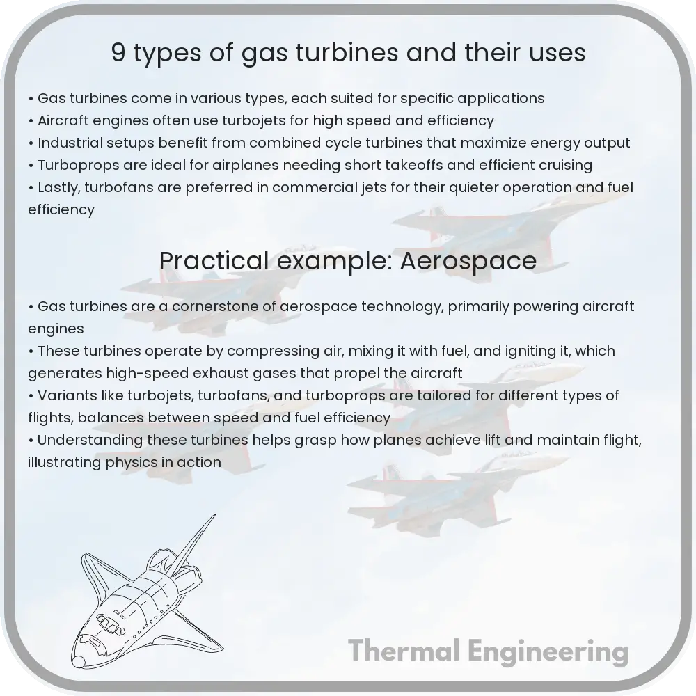
9 Types of Gas Turbines and Their Uses

Learn about the various types and uses of gas turbines, from power generation to aircraft propulsion.

9 Types of Gas Turbines and Their Uses

Introduction to Gas Turbines

Gas turbines are a crucial component in various engineering applications, ranging from power generation to aircraft propulsion. These machines convert natural gas or other fuels into mechanical energy, which in turn can be converted into electrical power or used to propel an aircraft. Understanding the different types of gas turbines and their specific applications is essential for professionals in engineering and related fields.

Types of Gas Turbines and Their Uses

  • Aero-Derivative Gas Turbines
  • As the name suggests, aero-derivative gas turbines are derived from jet engine designs and are optimized for mobility and flexibility. They are lighter and can start up or shut down quickly, making them ideal for providing temporary power or serving as backup systems in emergencies. They are commonly used in applications where quick power is needed, such as in peak shaving for electric utilities and in portable power plants.

  • Industrial (Heavy-Duty) Gas Turbines
  • Industrial gas turbines are designed for stationary power generation. These turbines are larger and more robust, specially engineered for long-term use. They are prominently used in power plants and in industrial environments where reliable, continuous power output is a priority. Compared to aero-derivatives, they have a higher power output and are more efficient in continuous operation scenarios.

  • Microturbines
  • Microturbines are small combustion turbines that can produce up to 1000 kilowatts of power. They are used in small scale power generation applications and more commonly in combined heat and power (CHP) systems. Their compact size makes them suitable for residential buildings, small businesses, and remote locations like oil and gas fields.

  • Radial Gas Turbines
  • Radial gas turbines are characterized by their radial flow compressors and turbines, as opposed to the more common axial flow in larger turbines. They are typically used in small applications, such as in auxiliary power units (APUs) for aircraft or in compact machinery where space is a constraint.

  • Turboshaft Engines
  • Turboshaft engines are a type of gas turbine optimized to produce shaft power rather than jet thrust. They are primarily used in helicopters and other aircraft where a compact, high-power engine is required. Beyond aviation, they are also used in power generation and marine propulsion.

  • Turbojet Engines
  • Turbojet engines were among the first types of gas turbines developed. They generate thrust by ejecting a high-speed jet of gases. These engines are mainly used in older model aircraft. Although largely superseded by more efficient turbine designs, turbojets are still used in specific military applications and for research purposes.

  • Turbofan Engines
  • Turbofan engines are the most common type found in modern commercial aircraft. They are similar to turbojets but include a fan that produces additional thrust by bypassing the core turbine, improving efficiency. This makes turbofan engines suited for commercial airliners, which require both high thrust and good fuel efficiency.

  • Gas Turbine Locomotives
  • While not as common today, gas turbine locomotives were explored as an alternative to diesel engines, particularly in the mid-20th century. Offering powerful performance, these locomotives were used primarily during periods of low diesel fuel availability but were eventually phased out due to high fuel consumption and operational costs.

  • Marine Gas Turbines
  • Used primarily in fast ships like frigates and corvettes, marine gas turbines are valued for their high power-to-weight ratio, a critical factor in naval applications. These turbines are similar to aero-derivative turbines, optimized for the sea environment where quick acceleration and high-speed operation are required.

Conclusion

Gas turbines play a pivotal role in both everyday and specialized applications. From powering the largest power plants to propelling high-speed jets, the versatility and efficiency of gas turbines make them indispensable in modern engineering. Understanding the different types of gas turbines helps in selecting the right turbine for the right application, ultimately leading to better performance and efficiency.

5 Types of Fluid Resistance and Its Impact

Fluid resistance, also known as drag or fluid friction, is crucial in engineering to optimize designs in aerospace, automotive, and marine fields.

5 Types of Fluid Resistance and Its Impact

Understanding Fluid Resistance: Types and Impacts

Fluid resistance, often referred to as drag or fluid friction, plays a crucial role in various engineering applications, from designing aerodynamic vehicles to optimizing pipe systems for fluid transport. This phenomenon occurs due to the interactions between a fluid and the surface of objects moving through it, or when objects move through a stationary fluid. Understanding the different types of fluid resistance and their impacts is essential for engineers to design more efficient and effective solutions in fields like aerospace, automotive, and marine engineering.

Types of Fluid Resistance

  • Laminar Skin Friction
  • Laminar skin friction occurs when a fluid flows in parallel layers, with no disruption between the layers. This type of resistance is dominant in scenarios where fluid flows smoothly and steadily over an object, typically at lower speeds and with less viscous fluids. The resistance is caused primarily by the viscosity of the fluid, and it is calculated using the formula:
    \[ F_d = c_f \times \frac{1}{2} \times \rho \times V^2 \times A \] Where \( F_d \) is the drag force, \( c_f \) is the coefficient of friction drag, \( \rho \) is the fluid density, \( V \) is the flow velocity, and \( A \) is the surface area in contact with the fluid.

  • Turbulent Skin Friction
  • Unlike laminar skin friction, turbulent skin friction occurs when the fluid flows in an irregular manner, causing eddies and swirls. This type generally appears at higher velocities or with more viscous fluids, and it covers a larger area of the object’s surface due to the chaotic nature of turbulent flow. The drag force from turbulent friction is usually higher than that from laminar friction and is also described using a variation of the drag equation, adjusted for the turbulent flow characteristics.

  • Pressure (Form) Drag
  • Pressure drag results from the shape of an object. It occurs because of the pressure differential created between the front and back of an object as it moves through a fluid. This drag is more significant for blunt or non-streamlined objects, as these shapes create larger wake zones where the fluid velocity is much slower, leading to higher pressure drag. Engineers reduce pressure drag by optimizing the shape of objects (streamlining), allowing the fluid to flow more smoothly around them.

  • Wave Drag
  • Wave drag occurs primarily on objects moving through a fluid at or near the speed of sound in that medium, or on watercraft moving near the surface at high speeds. This resistance emerges from the creation of shock waves or bow waves, which dissipate energy. It is particularly important in aerospace and naval engineering, where speeds can induce significant shock and wave formations.

  • Induced Drag
  • Induced drag is relevant primarily in aerodynamics, particularly for wings and airfoils. It arises due to the creation of vortices at the wingtips as the aircraft lift generates a pressure differential between the upper and lower surfaces of the wing. This type of drag is dependent on the aspect ratio of the wing and overall aircraft design.

Impacts of Fluid Resistance

Understanding and managing fluid resistance is critical in enhancing the efficiency, performance, and safety of various engineering systems. Here are some impacts:

  1. Energy Efficiency: Reducing fluid resistance directly correlates with lower energy consumption, particularly in vehicles and aircraft, where minimizing drag is crucial for fuel efficiency.
  2. Operational Performance: Efficient management of fluid resistance improves the speed and handling of vehicles and aircraft, contributing to better performance and operational capabilities.
  3. Structural Integrity: Excessive fluid resistance can lead to increased structural stress and potential failure. Properly accounting for fluid resistance in design helps ensure the longevity and safety of structures.
  4. Economic Impact: Lower fluid resistance can significantly reduce operational costs associated with fuel and maintenance, providing economic benefits to industries such as transportation and logistics.

By comprehensively understanding and applying principles related to fluid resistance, engineers can create designs that not only meet but exceed the current standards of efficiency and functionality in their respective fields.

Heat dissipation in high-power LEDs

Explore the essentials of heat dissipation in high-power LEDs, focusing on its impact on performance, efficiency, and lifespan.

Heat dissipation in high-power LEDs

Understanding Heat Dissipation in High-Power LEDs

Light Emitting Diodes (LEDs) have revolutionized the lighting industry with their energy efficiency and longevity. However, as the power and brightness of these LEDs increase, managing the heat they produce becomes a crucial engineering challenge. This article will explore the fundamentals of heat dissipation in high-power LEDs and why it is essential for maintaining their performance and lifespan.

Why Heat Dissipation is Important for LEDs

LEDs convert electrical energy into light efficiently; however, not all of the electrical energy is converted into light. A significant portion is converted into heat. In high-power LEDs, the amount of heat generated is considerable and can adversely affect the LED’s performance by:

  • Reducing the light output (luminous efficacy)
  • Altering the color quality
  • Shortening the operational lifespan

Effective heat management is therefore vital to prevent these adverse effects and ensure the LED functions within its intended specifications.

How Heat is Generated in LEDs

Heat generation in LEDs occurs primarily at the junction where the electrical energy is converted into light. This region, known as the p-n junction, operates efficiently only within a specific temperature range. Exceeding this range can cause permanent damage or failure of the LED. The heat must be removed from the junction and dissipated properly to maintain optimal operating conditions.

Methods of Heat Dissipation in LEDs

To manage the heat effectively, several engineering solutions are employed:

  • Heat Sinks: The most common method of heat dissipation. Heat sinks are usually made of aluminum and have a large surface area to maximize heat transfer to the surrounding environment.
  • Thermal Pads: These help enhance the thermal connectivity between the LED and the heat sink.
  • Thermal Grease: Often used alongside heat sinks to improve the interface by filling air gaps, thus enhancing heat conduction.
  • Active Cooling Systems: In very high-power applications, fans or cooling systems might be necessary to aid in heat dissipation.

Thermal Management Design

When designing a thermal management system for LEDs, engineers must consider several factors:

  • Material selection for heat sinks and interfaces depending on thermal conductivity and environmental durability.
  • Size and shape of the heat sink, which depend on the amount of heat to be dissipated and the physical space available.
  • The ambient temperature where the LED will be operated. Higher ambient temperatures require more efficient heat dissipation mechanisms.

Advanced computational methods such as Computational Fluid Dynamics (CFD) and Finite Element Analysis (FEA) are often used to simulate and optimize the heat dissipation performance before physical prototypes are created.

Impact of Enhanced Heat Dissipation

Improving heat dissipation in high-power LEDs can have profound impacts:

  • Increased Efficiency: Efficient thermal management can increase the overall efficiency of LEDs as less energy is wasted as heat.
  • Enhanced Performance: Better heat dissipation maintains the LED’s color stability and brightness over time.
  • Extended Lifespan: Heat management directly correlates with the operational life of the LED. Effective heat dissipation systems extend the lifespan significantly.

In summary, effective heat dissipation is critical for maximizing the performance and durability of high-power LEDs. Through the use of various thermal management techniques and careful design considerations, engineers can greatly improve the functionality and longevity of LED technologies, ensuring they meet the demanding requirements of modern lighting applications.

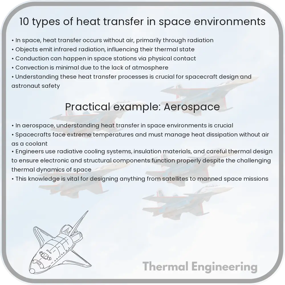
10 Types of Heat Transfer in Space Environments

Explore 10 heat transfer mechanisms essential for spacecraft thermal management in space environments, focusing on radiation, solar heating, and more.

10 Types of Heat Transfer in Space Environments

Understanding Heat Transfer in Space Environments

Heat transfer in space is a critical area of study, particularly in aerospace engineering, where understanding the thermal management of spacecraft and satellites is essential for their successful operation. Unlike on Earth, space does not have an atmosphere for convective heat transfer, which influences the design and functionality of space-going hardware. Here, we will explore 10 types of heat transfer mechanisms encountered in space environments.

1. Radiation

Radiation is the primary mode of heat transfer in the void of space. It involves the emission of electromagnetic waves that can travel through the vacuum. Every object at a temperature above absolute zero emits radiation, and the amount of energy emitted is governed by the Stefan-Boltzmann law:

E = σAT4

where E is the radiant energy per unit time, σ is the Stefan-Boltzmann constant, A is the emitting surface area, and T is the absolute temperature in Kelvin.

2. Solar Heating

Solar heating occurs when a spacecraft is directly exposed to the sun. The Sun’s rays can significantly increase the temperature of the spacecraft, requiring engineers to implement protective thermal coatings and heat rejection systems to manage the absorption of solar energy.

3. Albedo Radiation

Albedo radiation refers to the reflection of solar radiation off a planet or moon’s surface that later strikes a spacecraft. This radiation depends on the reflective properties of the celestial body’s surface or atmosphere.

4. Earth Infrared Radiation

Earth-based infrared radiation is significant for low Earth orbit satellites. The Earth absorbs solar energy and re-emits it as infrared radiation, which can increase the thermal load on nearby spacecraft.

5. Electrical Heating

Internal electrical components like processors and battery units generate heat. Managing this heat to avoid overheating and ensure continued function is a major aspect of spacecraft design.

6. Equipment Dissipation

Apart from electrical components, other onboard equipment such as mechanical devices and scientific instruments also dissipate heat during operation, contributing to the heat load inside the spacecraft.

7. Thermal Cycling

Thermal cycling occurs due to the periodic exposure of the spacecraft to different thermal environments, such as moving from the Sun-lit side of a planet into its shadow. This results in expansion and contraction of materials, potentially inducing structural stresses.

8. Conductive Coupling

In space, conductive heat transfer can occur between different parts of the spacecraft that are in physical contact. Engineers use insulation and careful material selection to manage unwanted conductive heat paths.

9. Radiative Coupling

Components within the spacecraft can also exchange heat amongst themselves via radiation. This internal radiative transfer can affect the spacecraft’s thermal equilibrium and requires careful design of the internal layout and surface properties.

10. Evaporative Cooling

Although less common, evaporative cooling can be used in space missions. This process involves the expulsion of heat through the sublimation or evaporation of materials, used in specialized systems like Heat Rejection Systems in some advanced spacecraft.

Each of these heat transfer modes poses unique challenges in the design and operation of spacecraft. Effective thermal management ensures the reliability and longevity of space missions, protecting equipment from extreme temperature changes and enabling normal operation in the harsh environment of space.

4 Types of Cooling Systems in Nuclear Reactors

Learn about the various cooling systems in nuclear reactors, including LWRs, GCRs, SFRs, and MSRs, and their roles in safe and efficient energy production.

4 Types of Cooling Systems in Nuclear Reactors

Understanding the Cooling Systems in Nuclear Reactors

Nuclear reactors are a critical component in the generation of nuclear power, and their safe operation is paramount to both environmental and public health. One of the key aspects of ensuring a nuclear reactor operates safely is effective cooling. The cooling system in a nuclear reactor serves to remove the heat generated during the nuclear fission process, thereby preventing the reactor from overheating and potentially causing a meltdown. There are several types of cooling systems employed in nuclear reactors, each with its own specific design and function. Let’s explore four principal types of cooling systems used in nuclear reactors.

1. Light Water Reactors (LWRs)

Light Water Reactors are the most common type of nuclear reactor, and they utilize water as both a coolant and a neutron moderator. The fundamental types of LWRs are the Pressurized Water Reactor (PWR) and the Boiling Water Reactor (BWR).

  • Pressurized Water Reactor (PWR): In PWRs, water is heated under high pressure, preventing it from boiling even at temperatures around 320°C. The hot water then flows into a heat exchanger (steam generator) where it transfers its heat to a secondary water line, turning it into steam. The steam then drives a turbine generator to produce electricity.
  • Boiling Water Reactor (BWR): Unlike PWRs, in BWRs, the reactor core heats water, which is allowed to boil directly within the reactor core under lower pressure than PWRs. The produced steam directly drives the turbine generator.

2. Gas-Cooled Reactors (GCRs)

Gas-cooled reactors use carbon dioxide or helium as a coolant instead of water. GCRs operate at higher temperatures than LWRs, making them more efficient in terms of energy conversion.

  • Advanced Gas-cooled Reactor (AGR): AGRs use carbon dioxide as a coolant and graphite as a moderator, operating at higher temperatures than traditional gas-cooled reactors, thus offering improved thermal efficiency.
  • High-Temperature Gas-cooled Reactor (HTGR): This reactor type uses helium as a coolant and can reach temperatures as high as 750°C, significantly enhancing efficiency in power generation.

3. Sodium-Cooled Fast Reactor (SFR)

Developed more recently, SFRs use liquid sodium instead of water as a coolant, enabling the reactor to operate at higher temperatures without the risk of steam explosion, as sodium does not change state at operational temperatures. The high thermal conductivity and capacity of sodium make it a highly effective coolant, which also allows for a more compact reactor design.

4. Molten Salt Reactors (MSRs)

MSRs use a circulating molten salt mixture as the primary coolant. Unlike conventional solid fuel elements, the fuel in an MSR is dissolved in the coolant itself. This can operate at high temperatures without reaching high pressures, and the liquid nature of the fuel allows for passive safety features, such as the draining of the molten salt into a passive cooling tank to prevent overheating.

Conclusion

The choice of cooling system in a nuclear reactor impacts its efficiency, safety, and feasibility. With advancements in technology, new cooling systems such as SFRs and MSRs present innovative ways to manage reactor heat and enhance safety features. Each system offers distinct advantages and challenges, shaping the future of nuclear energy significantly. As we continue to push for safer and more efficient nuclear power, understanding and improving these cooling systems remain a central focus in nuclear engineering.

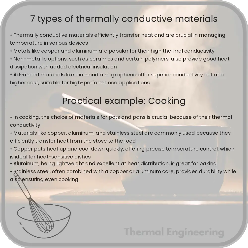
7 Types of Thermally Conductive Materials

Learn about thermally conductive materials used to enhance device efficiency and longevity by optimizing heat distribution.

7 Types of Thermally Conductive Materials

Introduction to Thermally Conductive Materials

Thermally conductive materials are used across various industries to manage heat and improve the efficiency and longevity of electronic devices, mechanical components, and structures. These materials optimize heat distribution, helping to dissipate heat away from critical parts to avoid overheating. Here, we explore seven common types of thermally conductive materials, each having unique characteristics that make them suitable for specific applications.

Metals

  • Copper: Known for its excellent thermal conductivity, copper is widely used in electronic equipment, heat exchangers, and cooling systems. It has a thermal conductivity of approximately 401 W/m*K, which makes it very effective in managing heat.
  • Aluminum: While not as conductive as copper, aluminum offers a lighter weight option with a thermal conductivity of about 237 W/m*K. It’s commonly used in automotive and aerospace industries where weight is a critical factor.
  • Silver: Although expensive, silver has the highest thermal conductivity of all metals, measuring up to 429 W/m*K. Its use is often limited to specialized applications where superior thermal management is necessary.

Ceramics

  • Aluminum Nitride: With a thermal conductivity as high as 320 W/m*K, aluminum nitride is used for its excellent ability to manage heat in electronic substrates and semiconductor devices.
  • Boron Nitride: This material stands out with a thermal conductivity range from 20 to 600 W/m*K, depending upon its form (cubic or hexagonal). It’s also electrically insulating, making it ideal for electronics applications.

Composite Materials

Composites are formed from two or more materials with differing properties to achieve superior thermal performance that individual components alone cannot provide.

  • Carbon Fiber Reinforced Polymer (CFRP): Integrating carbon fiber with polymer can enhance the thermal conductivity while remaining lightweight. These composites are used in situations where high strength and good heat dissipation are required.

Phase Change Materials (PCMs)

PCMs can absorb or release a large amount of heat at specific temperatures as they melt and solidify, making them useful in thermal management systems.

  • Paraffin Waxes: These are common PCMs with a typical melting point range suitable for low to medium temperature applications, like in building cooling systems.
  • Salt Hydrates: Salt hydrates can be used as PCMs with higher phase change temperatures, suitable for thermal storage systems in solar power plants.

Conclusion

The choice of thermally conductive materials largely depends on the specific heat management requirements of an application. Metals like copper and aluminum are staples for their high conductivity and durability. Ceramics offer excellent high-temperature stability and electrical insulation. Composites and PCMs provide customizable thermal properties that can be tailored to specific needs. Understanding these materials helps in selecting the right heat management solution to enhance performance and lifespan of components.

7 Types of Fluid Dynamics Simulations for Design

Learn about fluid dynamics simulations and their importance in engineering design, including CFD, laminar and turbulent flows, and more.

7 Types of Fluid Dynamics Simulations for Design

Understanding Fluid Dynamics Simulations in Design

Fluid dynamics plays a critical role in the design and development of various engineering systems, from aeroplanes and automobiles to bridges and HVAC systems in buildings. By utilizing fluid dynamics simulations, engineers can predict and analyze the behavior of fluids within these systems, leading to more efficient and effective designs. Here, we explore seven key types of fluid dynamics simulations commonly used in the engineering field.

1. Computational Fluid Dynamics (CFD)

Computational Fluid Dynamics (CFD) is a branch of fluid mechanics that uses numerical analysis and data structures to solve and analyze problems involving fluid flows. Engineers use CFD to simulate the flow of gases and liquids, heat transfer, and associated phenomena in various designs. Applications range from optimizing the aerodynamic shape of a car to enhancing the cooling of electronic devices.

2. Laminar vs. Turbulent Flow Simulations

Fluid flow can be either laminar or turbulent. Laminar flow is smooth and orderly, often modeled at lower velocities, while turbulent flow is chaotic and irregular. Understanding the transition from laminar to turbulent flow is crucial for designs where fluid resistance and heat transfer rates are significant, such as in pipelines, aircraft wings, and HVAC systems.

3. Multiphase Flow Simulation

Multiphase flow simulations are used when different phases of matter (e.g., solid, liquid, and gas) interact in a system. This type of simulation is essential in industries like oil and gas, chemical processing, and wastewater treatment, where it is crucial to understand how different materials interact under various conditions.

4. Heat Transfer Simulations

Engineers often need to analyze how heat is transferred in fluid mediums such as air or water. Heat transfer simulations help in designing systems like radiators, heat exchangers, and air conditioning units, ensuring they operate efficiently and maintain optimal temperature conditions.

5. Incompressible Flow Simulations

Incompressible flow simulations are used when the fluid density remains constant within the flow field. This assumption simplifies the mathematical modeling and is typically applied to liquids or gases moving at speeds much lower than the speed of sound. Such simulations are crucial in hydraulic systems and water treatment facilities.

6. Compressible Flow Simulations

When dealing with gases at high speeds, such as in jet engines or supersonic aircraft designs, compressible flow simulations become necessary. These simulations account for changes in density and state of the gas as it moves through different pressures and temperatures.

7. Aerodynamics Simulation

Aerodynamics simulation is a subset of fluid dynamics specifically concerned with the interaction between air and solid bodies. This type of simulation is crucial in designing efficient and safe vehicles, aircraft, and even buildings, helping to analyze how air flows around objects, thereby affecting speed, fuel efficiency, and structural integrity.

Conclusion

Each type of fluid dynamics simulation offers unique insights that are crucial for the design and optimization of engineering systems. By understanding and applying these simulations, engineers can significantly improve the performance, safety, and efficiency of their designs, ultimately leading to more innovative solutions in various industries.