Facebook Instagram Youtube Twitter

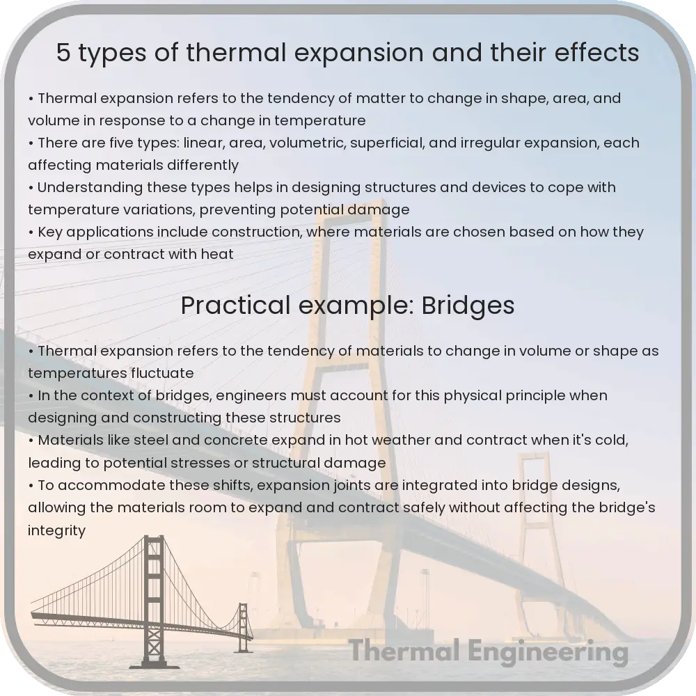
5 Types of Thermal Expansion and Their Effects

Learn about thermal expansion, its various types such as linear, area, volumetric, anisotropic, and differential expansion, and their practical implications.
5 Types of Thermal Expansion and Their Effects

Understanding Thermal Expansion: 5 Types and Their Effects

Thermal expansion refers to the tendency of matter to change its shape, area, and volume in response to a change in temperature. Virtually all substances expand when heated—the degree and type of expansion, however, vary depending on the material properties and the way the material interacts with heat. This phenomenon has significant implications in engineering and everyday life, as it affects everything from the construction of bridges and railways to the design of electronic devices. Let’s explore five common types of thermal expansion and their effects in practical applications.

1. Linear Expansion

Linear expansion is the change in length of materials as a response to temperature changes. This is most relevant for objects that are much longer in one dimension than in the others, such as rods and beams. The linear expansion can be calculated using the formula:

L = L0(1 + αΔT)

where L0 is the original length, α is the coefficient of linear expansion, and ΔT is the change in temperature. Linear expansion is crucially accounted for in engineering applications such as the construction of rail tracks and bridges, which might otherwise buckle under thermal stress.

2. Area Expansion

When heat is applied to a two-dimensional object like a sheet of metal, its area expands. Area expansion can be estimated by modifying the linear expansion formula to account for two dimensions:

A = A0(1 + 2αΔT)

Here, A0 is the original area. The factor of 2 indicates that the expansion occurs both in length and width. This type of expansion is particularly important in applications such as the manufacturing of precision parts in engineering and technology, where small changes in area can lead to significant function issues.

3. Volumetric Expansion

Volumetric expansion occurs when a three-dimensional object expands due to an increase in temperature. It is critical for materials used in containers and systems designed to hold fluids. The formula for volumetric expansion is:

V = V0(1 + 3αΔT)

Where V0 is the original volume, and the coefficient is multiplied by 3, reflecting expansion in three spatial directions. This principle is essential for the design of anything from fuel tanks to thermal expansion joints in piping systems.

4. Anisotropic Expansion

Anisotropic expansion refers to materials that have different rates of expansion in different directions. This characteristic is typical of crystalline materials where the atomic arrangement varies along different axes. Engineers must consider anisotropic expansion when using these materials in high precision devices such as lasers or satellites, where directional dimensional stability is paramount.

5. Differential Expansion

Differential expansion occurs when different parts of a composite object expand at different rates due to variations in material properties or geometric considerations. This can lead to mechanical stresses and potential failure. An everyday example is bimetallic strips used in thermostats, where two metals expand at different rates to bend the strip and break or make contact, activating a switch according to the temperature.

Understanding these types of thermal expansion and their respective formulas enables engineers to design more stable and reliable structures and devices. It also helps in developing innovative solutions that can accommodate or exploit these physical changes in materials brought about by temperature changes.

8 Types of Fluid Dynamic Analysis Tools

Learn about the eight essential fluid dynamic analysis tools used by engineers in various fields, from aerospace to food processing.

8 Types of Fluid Dynamic Analysis Tools

8 Types of Fluid Dynamic Analysis Tools

Fluid dynamics is a critical area of engineering that involves the study of fluids in motion. It encompasses a variety of applications, from designing aircraft to predicting weather patterns. Engineers use numerous tools to analyze fluid flow, each tailored for specific tasks. Below, we explore eight key types of fluid dynamic analysis tools.

1. Computational Fluid Dynamics (CFD) Software

CFD software allows engineers to simulate and analyze the behavior of fluids in realistic scenarios. It uses numerical methods and algorithms to solve and analyze problems that involve fluid flows. Commonly used CFD software includes ANSYS Fluent, OpenFOAM, and Autodesk CFD.

2. Wind Tunnels

Wind tunnels are experimental setups that enable engineers to study air flow around objects. They are essential in aerospace engineering for testing the aerodynamic properties of aircraft and other vehicles. Wind tunnels can be either open-circuit or closed-circuit, depending on the design requirements.

3. Particle Image Velocimetry (PIV)

PIV is an optical method for visualizing and measuring the flow field within fluid flows. It works by seeding the fluid with tracer particles which are illuminated by a laser sheet. The motion of these particles is captured in images, and the velocity field is calculated from their displacements.

4. Laser Doppler Anemometry (LDA)

LDA is another laser-based tool used to measure the velocity in fluid flows. It relies on the Doppler effect, detecting frequency shifts in laser light scattered by particles moving within the fluid.

5. Hot-Wire Anemometry

In hot-wire anemometry, a thin wire is heated up and exposed to the fluid flow. The cooling effect of the fluid on the wire is proportional to the speed of the flow, allowing for measurement of flow velocity. This tool is commonly used in research and development processes.

6. Flow Visualization Techniques

Flow visualization involves using various methods to make fluid flow patterns visible. This may include the use of smoke, dyes, or bubbles depending on the fluid being tested. Techniques like schlieren photography, which captures changes in fluid density, are also used extensively.

7. Manometers

Manometers are devices used to measure pressure difference in fluid flows. They are simple yet accurate, and can be used for both gases and liquids. Variants such as digital manometers are also increasingly common in modern fluid dynamics labs.

8. Rheometers

Rheometers are used to measure the properties of non-Newtonian fluids, where viscosity changes with flow conditions. These tools provide detailed insight into the complex behavior of such fluids and are vital in industries like food processing and polymers.

Understanding the various tools used in fluid dynamic analysis helps engineers choose the most appropriate method for their specific needs, leading to more accurate and effective designs. Whether for academic research, industrial applications, or innovative engineering projects, these tools form the backbone of fluid dynamic studies and development.

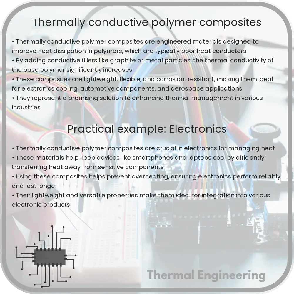
Thermally conductive polymer composites

Learn about thermally conductive polymer composites, engineered materials enhancing polymer thermal conductivity for diverse applications.

Thermally conductive polymer composites

Understanding Thermally Conductive Polymer Composites

Thermally conductive polymer composites are engineered materials designed to improve the thermal conductivity of polymers, which are typically insulative in nature. These composites are a blend of a polymer matrix and thermally conductive fillers. They play a critical role in electronic applications, where effective heat dissipation is crucial for reliability and performance.

Composition of Thermally Conductive Polymer Composites

The typical components of thermally conductive polymer composites include:

  • Polymer Matrix: This can be a thermoset (e.g., epoxy, polyester) or a thermoplastic (e.g., polyamide, polycarbonate). The choice of polymer affects the composite’s mechanical, thermal, and processing properties.
  • Conductive Fillers: These are materials with high thermal conductivity, such as graphite, boron nitride, aluminum oxide, or silver flakes. The type and amount of filler incorporated into the polymer matrix significantly influence the thermal conductivity of the composite.
  • Interface Materials: These substances enhance the bonding and interaction between the polymer and the fillers, improving thermal transfer efficiency.

How They Work

The primary mechanism for heat conduction in these composites is through the network of conductive fillers. When these fillers are adequately dispersed within the polymer matrix and connected, they form pathways that facilitate heat flow. The efficiency of heat conduction in such materials largely depends on the filler content, filler shape and size, dispersion quality, and interface bonding quality.

Thermal Conductivity Mechanism

Thermal conductivity in polymers and their composites can be represented by Fourier’s Law of Heat Conduction:

q = -k * A * (dT/dx)

  • q represents the heat flux,
  • k is the thermal conductivity,
  • A is the area through which heat is being transferred,
  • dT/dx is the temperature gradient across the material.

In polymer composites, the value of k (thermal conductivity) is enhanced by the addition of conductive fillers. Higher filler contents and better connectivity generally lead to higher k values, thus better thermal management.

Applications

Thermally conductive polymer composites are utilized in various industries, including:

  • Electronics: Used in devices such as laptops, smartphones, and LED lights for heat dissipation components like heat sinks and thermal interface materials.
  • Automotive: Applied in electric vehicle battery packs and electronic control units where heat management is critical for safety and efficiency.
  • Aerospace: Employed for thermal management systems in spacecraft and satellites where high thermal conductivity and low weight are essential.

Advantages of Thermally Conductive Polymer Composites

These materials offer several benefits:

  • Lightweight: They are lighter than metals, which is advantageous in aerospace and automotive applications.
  • Corrosion Resistance: Polymers do not corrode like metals, making them suitable for harsh environments.
  • Ease of Processing: Polymer composites can be molded into complex shapes, which provides flexibility in design.
  • Cost-Effective: Generally, they are less expensive to produce compared to pure conductive metals or ceramics.

The development and utilization of thermally conductive polymer composites symbolize a significant advancement in material science, combining the benefits of polymers with the functionality of metals to address specific engineering challenges in thermal management.

9 Types of Industrial Fans and Blowers

Learn about the various types and uses of industrial fans and blowers, essential for multiple applications in various industries.

9 Types of Industrial Fans and Blowers

Introduction to Industrial Fans and Blowers

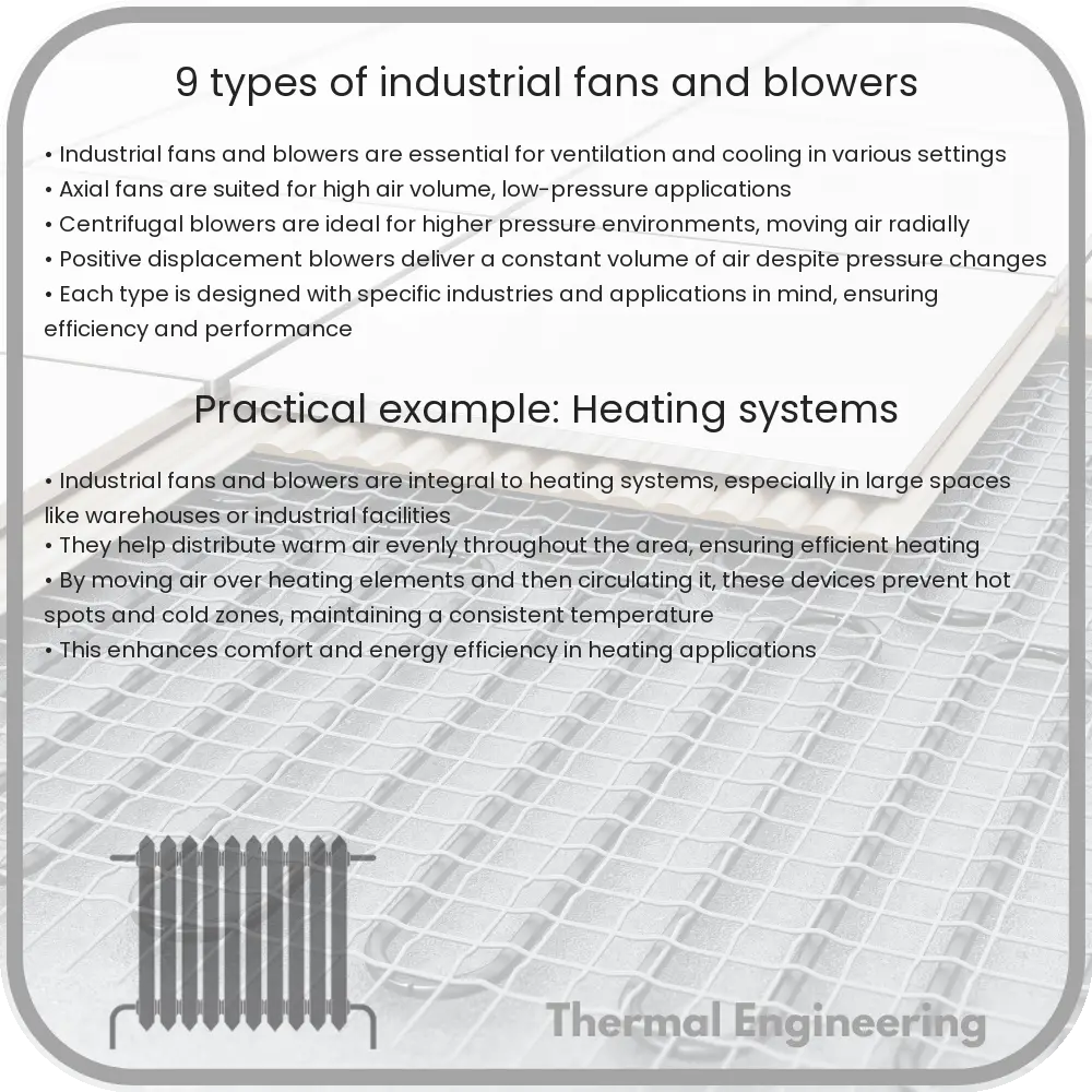
Industrial fans and blowers are essential components in various industrial applications, facilitating air movement and system ventilation. They play crucial roles in cooling, exhaust systems, and air supply in many sectors, including manufacturing, automotive, and construction. Understanding the different types can help in selecting the right equipment for specific industrial needs.

Centrifugal Fans

Centrifugal fans use a rotating impeller to increase the speed and volume of an air stream, which is then directed at a right angle to the fan’s intake. They are characterized by their radial discharge and are commonly used in situations where both flow and higher pressures are needed.

  1. Backward Inclined Fans: Ideal for applications requiring high-efficiency and low noise operations. These fans are suited for clean air applications.
  2. Forward Curved Fans: Also known as squirrel cage fans, they are typically used in heating and air conditioning systems due to their ability to move large volumes of air at low pressures.
  3. Radial Blade Fans: These are robust and can handle heavy dust loads. They are typically used in industries involving wood, metal, and other material handling that can result in debris being entrained in the airstream.

Axial Fans

In axial fans, the airflow is directed along the axis of rotation, allowing the air to move parallel through the impeller at all points. These are generally used for applications where a large volume of air needs to be moved across lower pressure differences.

  • Tube Axial Fans: Common in industrial and commercial settings, they are well-suited for moving air or gases through ducts, as in ventilation systems.
  • Vane Axial Fans: Similar to tube axial fans but with the addition of guide vanes that improve efficiency by straightening the airflow post-impeller rotation, minimizing turbulence.
  • Propeller Fans: Often found in agricultural applications for barn ventilation or in industrial settings for basic ventilation or cooling. These fans move a high volume of air at low pressure but are not suitable for ducted applications.

Specialized Blowers

Blowers are designed for applications requiring a relatively low airflow compared to the high static pressure they can providing. They are crucial in pneumatic conveying, vacuum loaders, and other industrial processes requiring effective high-pressure airflow.

  • Positive Displacement Blowers: These deliver a steady volume of air at varying pressures, suitable for operations demanding consistent airflow, like wastewater treatment facilities.
  • High-Pressure Blowers: Specifically designed to achieve higher pressures than typical centrifugal blowers; used in systems demanding high-pressure airflow such as combustion applications.
  • Rotary Blowers: Operating on the principle of positive displacement, these are used for applications requiring constant speed and flow. They are ideal for vacuum or compressed air systems.

Choosing the Right Fan or Blower

Selecting the right type of fan or blower depends on various factors such as application needs, desired airflow and pressure specifications, environmental conditions, and efficiency requirements. Understanding the specific operations and limitations of each type can aid in choosing the most appropriate model to enhance system performance and reliability.

Conclusion

Industrial fans and blowers are pivotal in maintaining air quality, temperature, and pressure in numerous industrial contexts. With the diverse types available, each tailored for different applications and specifications, businesses can optimize their processes by selecting the appropriate fans and blowers tailored to their specific needs.

3 Types of Radiative Heat Transfer Methods

Learn about the three types of radiative heat transfer: thermal radiation, solar radiation, and radiative cooling, and their applications in technology and sustainability.

3 Types of Radiative Heat Transfer Methods

Understanding the 3 Types of Radiative Heat Transfer

Heat transfer is a fundamental concept in both physics and engineering that describes the movement of heat from one place to another. One of the primary methods of heat transfer is radiation. Radiative heat transfer occurs without the need for a medium, unlike conduction or convection, meaning it can even happen through the vacuum of space. This type of heat transfer is especially important in understanding how the sun warms the Earth, how electronic devices dissipate heat, and in the design of heating systems. It relies on electromagnetic waves and operates at the speed of light.

1. Thermal Radiation

Thermal radiation is emitted by all objects that have a temperature above absolute zero. According to the Stefan-Boltzmann law, the power radiated from an object increases with the fourth power of its absolute temperature, which can be mathematically expressed as:

Power Radiated (P) = σ * A * T4

where:
σ (sigma) is the Stefan-Boltzmann constant, approximately equal to 5.67 x 10⁻⁸ W/m2K4,
A is the surface area of the object, and
T is the absolute temperature in Kelvin.

Thermal radiation is significant in engineering applications such as furnace design, thermal insulation, and thermal sensors.

2. Solar Radiation

Solar radiation is a specific type of radiative heat transfer from the sun, providing both light and heat to the Earth. The sun emits a broad spectrum of electromagnetic radiation, but most of what reaches the Earth is in the visible, ultraviolet, and infrared part of the spectrum. Solar radiation is crucial for life on Earth, driving photosynthesis in plants and influencing weather and climate patterns.

Solar energy technologies harness this radiation to generate electricity or heat through solar panels and solar thermal systems. The effectiveness of these technologies depends on the angle of incidence, atmospheric conditions, and the properties of materials used to capture or reflect solar energy.

3. Radiative Cooling

Radiative cooling is a passive cooling mechanism in which an object or a surface loses heat by emitting radiation. It occurs naturally at night when surfaces that have been heated during the day radiate their accumulated heat to the colder sky. This method is increasingly being used in the development of sustainable energy technologies.

Recent advancements include materials that are highly emissive in the infrared spectral range but reflect nearly all visible light, allowing for significant cooling even under direct sunlight. These materials have potential applications in cooling systems for buildings and vehicles, enhancing energy efficiency without additional energy consumption.

In summary, radiative heat transfer plays a crucial and versatile role in both natural and engineered systems. By understanding and manipulating this phenomenon, engineers can design more effective heating, cooling, and energy systems, contributing to advanced solutions in technology and environmental sustainability.

7 Types of Air Filters for HVAC Systems

Learn about seven common air filter types for HVAC systems, including fiberglass, pleated, and HEPA filters.

7 Types of Air Filters for HVAC Systems

7 Types of Air Filters for HVAC Systems

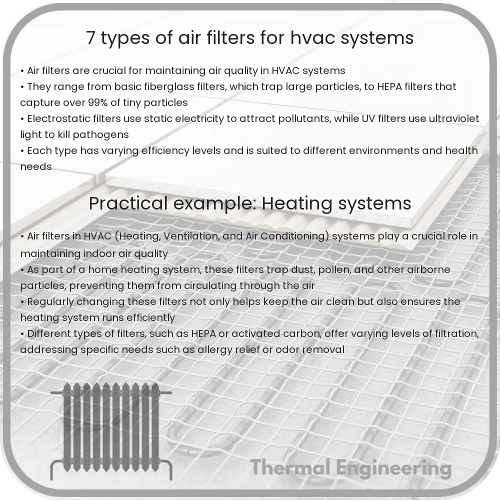
Air filters are integral components of Heating, Ventilation, and Air Conditioning (HVAC) systems, designed to improve indoor air quality by removing pollutants and particulates. Various types of air filters are engineered to fit different needs based on efficiency, cost, and filter capabilities. Here’s a look at seven common types of air filters used in HVAC systems.

Fiberglass Air Filters

Fiberglass air filters are among the most common and economical options. These filters are constructed from a flat, disposable panel of fiberglass fibers laid over each other to trap particles. Typically, fiberglass filters are designed to protect HVAC units rather than improving indoor air quality significantly, as they generally trap large dust particles and prevent them from clogging the HVAC system.

Pleated Media Filters

Made from polyester fabrics or cotton folds, pleated media filters offer a greater surface area to capture airborne particles. The pleats increase the efficiency in capturing particles such as pollen, mold spores, and pet dander. These filters balance cost and performance, making them popular among residential users who seek better air filtration without a significant increase in cost.

Electrostatic Filters

Electrostatic filters use self-charging fibers to attract particulates. These filters are effective in capturing small particles and are available in both disposable and reusable forms. The reusable electrostatic filters can be washed and reinserted. They are particularly useful for homes with pets or in high dust areas, as they can capture finer particles more effectively than fiberglass or basic pleated options.

HEPA Filters

High-Efficiency Particulate Air (HEPA) filters offer the highest level of air purification among common residential HVAC filters. They can trap at least 99.97% of particles that are 0.3 microns in diameter, including tobacco smoke, dust mites, and pollen. HEPA filters are typically used in hospitals and laboratories, where air quality requirements are stringent, but they are also increasingly used in residential settings for allergy and asthma sufferers.

Activated Carbon Filters

While not typically used for particulate removal, activated carbon filters excel in removing odors and volatile organic compounds (VOCs) from the air. These filters use a bed of activated carbon to chemically absorb pollutants as air passes through. They are commonly used in settings where odor control is a priority, such as in kitchens and pet areas.

UV Filters

UV filters use ultraviolet light to kill viruses, bacteria, and mold that may pass through the HVAC system. These filters are not effective against non-living pollutants or particulates, but they are excellent for improving the sanitary quality of the indoor air. UV filters are often used in conjunction with other filtering technologies to ensure comprehensive air purification.

Washable Air Filters

Washable or reusable air filters provide a long-term cost-effective solution for air filtration. Made typically from aluminum or plastic fibers, these filters can be removed, cleaned, and re-inserted into the HVAC system. While they require more maintenance, their durability and reusability make them suitable for those looking to minimize waste and ongoing costs.

Choosing the right air filter for your HVAC system depends on a variety of factors including the specific needs of your indoor environment, maintenance capabilities, and budget. Each type of filter brings its own benefits and limitations, hence understanding these will guide you in making an informed decision to ensure optimal air quality in your space.

10 Types of Steam Traps and Their Applications

Learn about steam traps, their crucial role in steam systems for energy efficiency and safety, and explore the different types used across various applications.

10 Types of Steam Traps and Their Applications

Understanding Steam Traps and Their Varieties

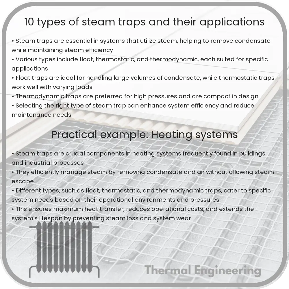
A steam trap is a device used to discharge condensate and non-condensable gases with a negligible consumption or loss of live steam. They are a critical component of steam systems and are vital in reducing energy loss, increasing efficiency, and improving system safety. There are several types of steam traps, each suited to specific operating conditions and applications. Below, we explore 10 common varieties of steam traps and their typical uses.

Types of Steam Traps

1. Mechanical Traps

  • Float Traps: These use a float ball that rises and falls in response to the condensate level, opening or closing the valve. They are effective in handling high capacities of condensate and are primarily used in applications where efficient heat transfer is necessary.
  • Inverted Bucket Traps: Rely on an inverted bucket that floats on the condensate and drops when steam arrives, sealing the trap. Suitable for high-pressure applications and notable for their durability.

2. Thermostatic Traps

  • Bimetallic Traps: Utilize bimetallic strips that bend with temperature changes, opening or closing the trap. Ideal for use with superheated steam.
  • Wax Thermostatic Element Traps: These traps operate using a wax element that expands and contracts with temperature variations to open or close the valve. Commonly used in lighter applications where minimal condensate is produced.
  • Bellows Traps: Feature a bellows filled with vapor pressure that expands or contracts with changing temperatures, making them suitable for applications with a steady range of temperatures.

3. Thermodynamic Traps

  • Disc Traps: Operate using a disc that moves up and down due to pressure fluctuations, allowing for the quick removal of condensate. These traps are compact and have a high tolerance for water hammer and corrosion.

4. Venturi Traps

  • Orifice Traps: Contain a fixed orifice and operate without moving parts, controlling flow through a variable orifice depending on the condensate load. They are known for their simplicity and low maintenance.

5. Specialized Traps

  • Impulse Traps: Utilize the kinetic energy of flash steam to operate valves. These types of traps are often employed where high efficiency is required and differential pressure is available.
  • Bi-Thermostatic Traps: Combine a bimetallic element and a bellows to handle varying conditions, frequently found in steam heating systems and drying cylinders.
  • Ball Float Traps: Similar to float traps but use a ball instead of a float. These are typically used in heavy-duty applications, handling large volumes of condensate efficiently.
  • Radiator Traps: Designed specifically for radiators, these traps use a thermostatic element to discharge condensate once it cools below steam temperature.
  • F&T (Float and Thermostatic) Traps: Combine the features of float traps with a thermostatic release of air, offering a mixture of capabilities ideal for heating applications and unit heaters.

Applications of Steam Traps

Steam traps are integral to the efficiency and safety of steam distribution systems. They are utilized in various applications, including heating installations, large steam systems in chemical plants, and power stations. Each type of steam trap is chosen based on specific factors like operating pressure, temperature conditions, required discharge capacity, and presence of non-condensable gases. Identifying and implementing the right kind of steam trap ensures optimal system performance and can substantially reduce energy costs.

Understanding these different types of steam traps and their applications provides a solid foundation in managing and maintaining a robust and efficient steam system. While choices can vary based on specific industry needs, the fundamental principles of condensate removal and energy efficiency remain constant, ensuring that steam systems across various applications continue to operate effectively.

6 Types of Natural Convection Applications in Engineering

Learn about natural convection, how it drives fluid movement without mechanical means, and its key applications in engineering.

6 Types of Natural Convection Applications in Engineering

Understanding Natural Convection: Its Role and Applications in Engineering

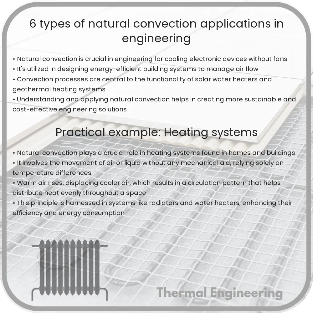
Natural convection is a fundamental heat transfer process where fluid motion is generated by the differences in density resulting from temperature variations in the fluid. Unlike forced convection, no external mechanical means (like fans or pumps) are required to circulate the fluid; the fluid movement is purely driven by natural forces. This process is critical in various engineering applications, affecting the design and efficiency of systems ranging from heating and cooling to power generation. Here are six crucial applications of natural convection in engineering:

1. Building Heating and Ventilation

One of the most common applications of natural convection is in building heating and ventilation systems. As air within a room is heated, typically by radiators or heaters, it expands and becomes less dense than the cooler air. The warmer, lighter air then rises, and cooler air falls towards the heater to be warmed, creating a convection current that helps to distribute heat throughout the room. This principle is also used in designing energy-efficient buildings, where natural air flow reduces the need for mechanical heating and cooling.

2. Cooling of Electronic Equipment

Natural convection is pivotal in cooling electronic components and devices to prevent overheating, which can lead to reduced efficiency or damage. In many electronic configurations, heat sinks are designed to enhance natural convection effectiveness, ensuring that warm air rises away from the device, thus pulling cooler air into its place. This application is commonly observed in the design of circuits and computer components, where passive cooling must be efficient yet unobtrusive.

3. Solar Panels

Solar panels often operate at higher efficiencies when they are kept at lower temperatures. Natural convection is used to cool these panels. The heat absorbed by the panels warms the air around them, causing it to rise and be replaced by cooler air. By designing the installation to enhance this effect, engineers can improve the performance and lifespan of solar panels.

4. Industrial Furnaces and Kilns

In industries that utilize furnaces and kilns, natural convection plays a crucial role in temperature regulation and distribution inside the chamber. By harnessing the movement of hot gases and air through the furnace, engineers can achieve more uniform temperature profiles, which are essential for processes like material processing, smelting, and ceramics manufacturing.

5. Geothermal Systems

Natural convection is also at the heart of geothermal heating systems. In geothermal heating, water in underground pipes is heated by the Earth’s natural heat. As this water becomes warmer and less dense, it rises and is replaced by cooler water from above, creating a natural cycle that can be used for heating buildings or generating electricity.

6. Atmospheric and Oceanic Circulations

While not an application in the traditional sense of engineering designs, understanding natural convection is crucial for predicting and modeling atmospheric and oceanic circulations. These natural processes are analogous to engineering systems, and the principles learned from them apply to a myriad of environmental engineering and climatic prediction models. Engineers and scientists use these principles to design better HVAC systems, predict weather patterns, and even in designing vehicles and structures that can withstand environmental forces.

In conclusion, natural convection is a powerful principle of physics that finds applications in diverse engineering fields. By understanding and harnessing this phenomenon, engineers can create more efficient, economical, and sustainable systems and contribute to a wide range of technological advancements.

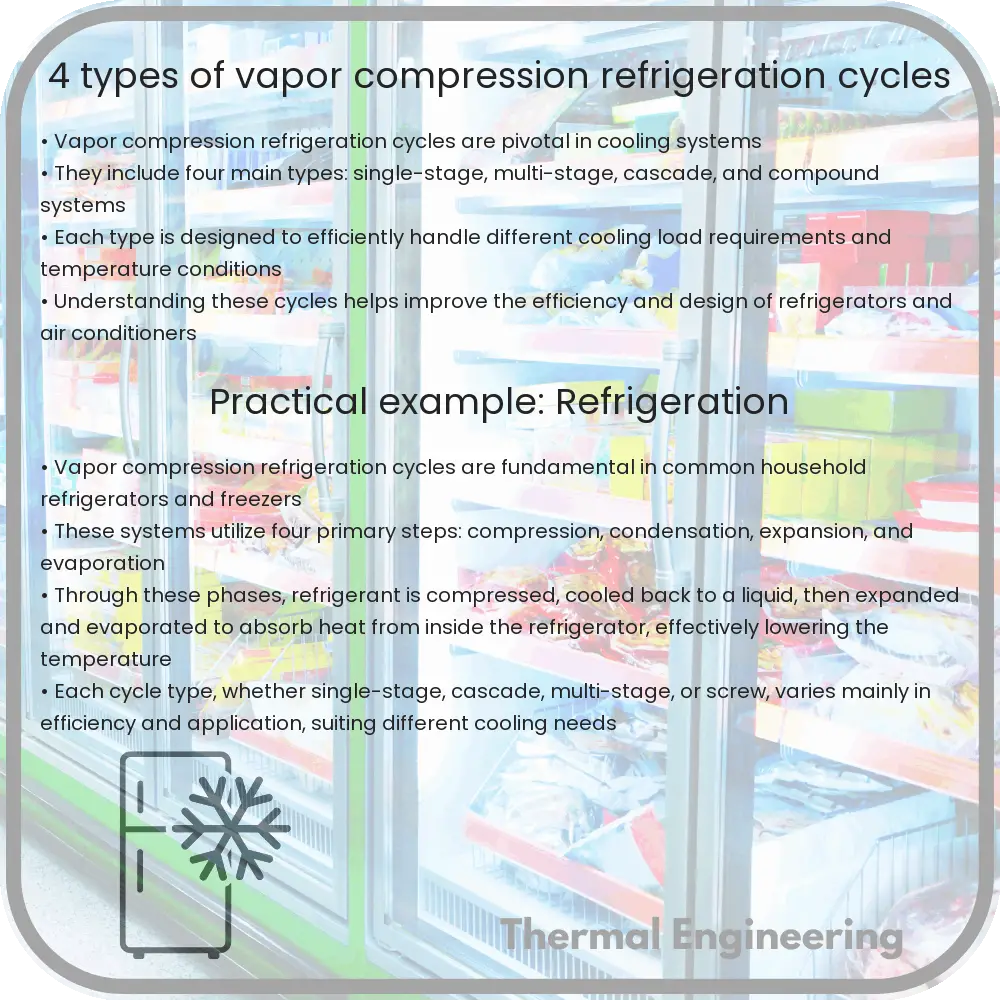
4 Types of Vapor Compression Refrigeration Cycles

Understand vapor compression refrigeration cycles, used in cooling technologies like refrigerators and air conditioners, focusing on their components and efficiency.

4 Types of Vapor Compression Refrigeration Cycles

Introduction to Vapor Compression Refrigeration Cycles

The vapor compression refrigeration cycle is a crucial method used in refrigerators, air conditioners, and heat pumps to transfer heat from one area to another. The process is based on the phase change of a refrigerant substance between its liquid and gaseous states. In this article, we will explore four common variants of the vapor compression refrigeration cycle and understand their applications and efficiencies.

1. Basic Vapor Compression Cycle

The basic vapor compression cycle involves four primary components: the compressor, condenser, expansion valve, and evaporator. The refrigerant flows through these components, undergoing various changes in state and pressure:

  • Compression: The compressor pumps the refrigerant vapor under high pressure, raising its temperature.
  • Condensation: The hot vapor then flows through the condenser where it releases heat to the surroundings and condenses into a high-pressure liquid.
  • Expansion: This high-pressure liquid passes through an expansion valve, reducing its pressure and causing it to cool down rapidly.
  • Evaporation: The low-pressure, cool liquid enters the evaporator where it absorbs heat from the environment and evaporates back into a vapor, thereby cooling the surrounding area.

2. Multi-stage Compression Cycle

In more complex systems, particularly where very low temperatures are needed, multi-stage compression cycles are used. These cycles incorporate multiple compressors and, in some cases, intercoolers between these compressors. The main purpose of using multiple compression stages is to improve the efficiency and capacity of the cycle:

  • Intercooling: Between the stages, the refrigerant is cooled using an intercooler, which reduces the work required by subsequent compression stages.
  • Phase Separation: An internal heat exchanger can also be included to provide subcooling and increase the cooling capacity.

3. Cascade Refrigeration Cycle

The cascade refrigeration cycle consists of two or more individual vapor compression cycles operating in series. Each cycle uses a different refrigerant and operates at a different temperature range, making the system suitable for applications requiring extremely low temperatures:

  • High-Temperature Side: Operates like a standard vapor compression cycle.
  • Low-Temperature Side: Uses the output from the high-temperature cycle to condense its refrigerant, allowing it to reach lower temperatures.

4. Economizer Cycle

The economizer cycle, also known as a subcooling cycle, adds an extra component called an economizer that increases the refrigeration effect without increasing the compressor’s work. This cycle is characterized by:

  • Economizer: Diverts some of the high-pressure liquid refrigerant through an expansion valve into the economizer where it evaporates and cools the remaining high-pressure liquid.
  • Improved Efficiency: This process effectively increases the cooling capacity and efficiency of the cycle by utilizing the same amount of compressor work more effectively.

Conclusion

Vapor compression refrigeration cycles come in various configurations, each designed to meet specific cooling requirements and efficiency standards. From simple household appliances to large-scale industrial systems, understanding these cycles helps in selecting the right refrigeration solution for your needs. Whether increasing the efficiency through multi-stage compression or achieving lower temperatures with cascade systems, these cycles form the backbone of modern refrigeration technology.

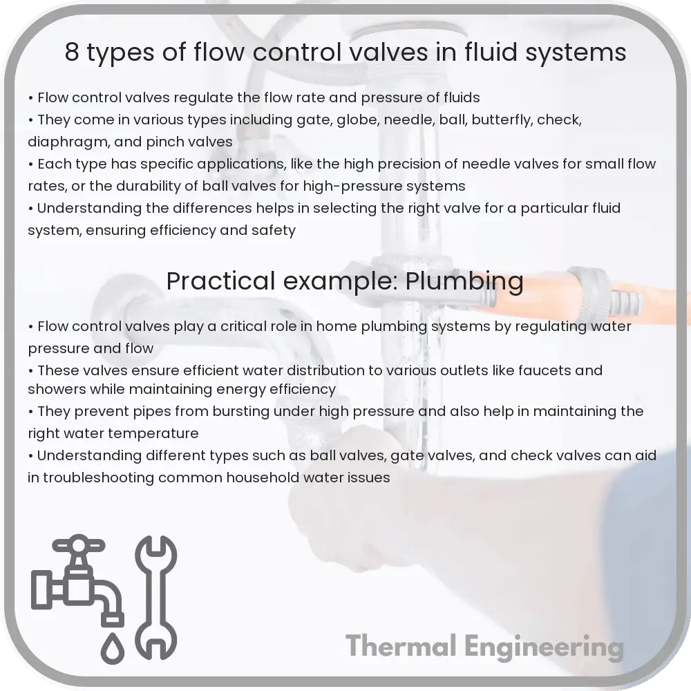
8 Types of Flow Control Valves in Fluid Systems

Learn about the various types of flow control valves such as ball, globe, and butterfly valves, and their roles in regulating fluid flow in systems.

8 Types of Flow Control Valves in Fluid Systems

Understanding Flow Control Valves in Fluid Systems

Flow control valves are crucial components in fluid systems, regulating the flow rate and pressure of liquids and gases. These valves ensure the efficient operation of systems, from simple plumbing to complex chemical processing plants. Let’s explore eight common types of flow control valves and their unique functions.

1. Ball Valves

Ball valves are characterized by a spherical disc that controls the flow through it. The valve operates using a rotary ball with a bore. By turning the valve handle, the ball rotates, aligning the bore perpendicular or parallel to the flow, thus blocking or allowing flow. Ball valves are known for their tight sealing and durability.

2. Globe Valves

Globe valves are used to regulate flow in a pipeline. They have a spherical body and a movable disk-type element that presses against a stationary ring seat, typically at a right angle to the pipe. These valves are excellent for throttling flow and offer precise flow control but generally have higher pressure drops.

3. Gate Valves

Gate valves control fluid flow by lifting a gate out of the path of the fluid. They are mainly used in the fully open or fully closed positions and are inappropriate for throttling purposes. Gate valves are often used in water and wastewater systems.

4. Butterfly Valves

Butterfly valves have a disk mounted on a rotating shaft. When the valve is closed, the disk completely blocks the line. When the valve is open, the disk is parallel to the flow of fluid. Butterfly valves are known for their compact design and are commonly used to modulate the flow.

5. Needle Valves

Needle valves are designed for precise flow control. They have a small, needle-shaped plunger that fits into a conical seat, allowing precise regulation of flow in small amounts. They are particularly useful in calibration applications.

6. Check Valves

Check valves are designed to allow fluid to flow in one direction only. They prevent backflow which can damage equipment or disrupt process conditions. Check valves automatically open with forward flow and close against reverse flow and are essential in pumping systems.

7. Diaphragm Valves

Diaphragm valves use a flexible diaphragm connected to a compressor that comes down against a saddle, thus stopping flow. They are particularly used in applications where purity and contamination prevention are critical such as in the pharmaceutical and food industries.

8. Pinch Valves

Pinch valves offer a practical way to control fluid flow. They have a rubber sleeve that is pinched by external forces to obstruct the flow. Pinch valves are ideal for handling slurries or liquids containing large amounts of suspended solids.

Conclusion

Choosing the right type of flow control valve depends on specific requirements such as the nature of the fluid, the flow rate, and the environmental conditions. Understanding the functionalities and appropriate applications of these various types of valves can help in making informed decisions for both industrial applications and daily utilities.