Facebook Instagram Youtube Twitter

5 Types of Thermal Bridges in Building Construction

Understanding the role of thermal bridges in building construction and their impact on energy efficiency.

5 Types of Thermal Bridges in Building Construction

Understanding Thermal Bridges in Building Construction

Thermal bridges are regions in a building’s envelope that allow more heat transfer compared to surrounding materials typically due to reduced thermal insulation. They can significantly impact a building’s energy efficiency, leading to increased energy consumption, higher costs, and discomfort due to cold spots. Knowing the types of thermal bridges and how they occur can help in designing more energy-efficient buildings. Here are five common types of thermal bridges found in building construction:

1. Structural Thermal Bridges

  • Material Continuity: Structural elements that penetrate the insulation layer, such as steel or concrete beams, create paths for heat to bypass the insulation.
  • Examples: Steel balconies that connect directly to the interior structure, concrete floor slabs that extend through the building envelope.

2. Geometric Thermal Bridges

These occur due to changes in the geometry or thickness of the building envelope. Sharp corners, edges, or junctions typically have less insulating material, which facilitates heat flow.

  • Common Locations: At junctions of walls and floors, window reveals, and corners of buildings.

3. Material Thermal Bridges

Material thermal bridges happen when materials with poor insulating properties are used within or between better-insulating materials.

  • Example: Using metal fasteners in insulated wall systems, concrete blocks in an otherwise insulated wall.

4. Installation Defects

Improper installation of insulation and building materials can lead to unintended thermal bridges. Gaps, cracks, or compressions in insulation materials can significantly reduce their effectiveness.

  • Typical Issues: Inadequate sealing around windows and doors, uneven insulation application, compressed insulation batts in wall cavities.

5. Repeating Thermal Bridges

These occur when a pattern of materials or structural elements create multiple, similar thermal bridges across a building envelope.

  • Example: Thermal bridging through metal stud framing in walls, where the metal studs consistently interrupt the insulation layer across large areas.

Addressing and Mitigating Thermal Bridges

To mitigate the effects of thermal bridges, builders and architects can employ various strategies:

  • Thermal Breaks: Use specific insulating materials designed to interrupt the path of heat flow through structural elements.
  • Improved Design: Design adjustments like increasing the continuity of insulation or changing geometric configurations can significantly reduce heat loss.
  • Quality Control: Ensuring proper installation and full coverage of insulation materials during the construction phase is crucial.

Addressing thermal bridges effectively enhances a building’s thermal performance, contributes to the sustainability of structures, and reduces operational costs. Understanding the types of thermal bridges and their implications is essential for advanced building design and energy-efficient building practices.

3 Types of Thermal Conductivity Measurements

Explore essential methods for measuring thermal conductivity, a key property in material science and engineering.

3 Types of Thermal Conductivity Measurements

Understanding Thermal Conductivity Measurements

Thermal conductivity is a fundamental property that measures a material’s ability to conduct heat. It is crucial in various engineering and scientific applications, from designing heat exchangers to manufacturing electronic devices. Measuring thermal conductivity accurately is vital for evaluating and selecting materials for specific heat management applications. There are several methods commonly used to measure the thermal conductivity of materials. Each technique has its unique setup, advantages, and limitations. Below, we explore three primary types of thermal conductivity measurements.

1. Steady-State Techniques

Steady-state methods are characterized by the requirement that the temperature does not change with time during measurement, implying that a steady state of heat flow has been established throughout the test sample. Among these techniques, two popular methods are the guarded hot plate method and the heat flow meter method.

  • Guarded Hot Plate Method: This method involves placing the material sample between two plates, with the lower plate heated to a higher temperature and the upper plate maintained at a lower temperature. Insulation surrounds the central heating plate to ensure minimal heat loss, providing a stable temperature gradient across the sample. The steady heat flow achieved allows for the calculation of thermal conductivity using the heat flow, the area through which the heat is transferred, and the temperature difference.
  • Heat Flow Meter Method: This approach uses a heat flow meter, which consists of a plate with known thermal conductivity values, sandwiched between the sample and a temperature-controlled plate. The heat flow meter is calibrated so that the heat passing through it can be calculated from the voltage produced by the thermopiles in the meter. This method is typically faster and suitable for insulating materials.

2. Transient Techniques

In contrast to steady-state techniques, transient methods assess how a material’s temperature changes over time in response to changes in heat flow. These methods are generally faster and can handle a broader range of materials, including fluids and high thermal conductivity solids.

  • Transient Hot Wire (THW) Method: This technique involves a thin wire, electrified and embedded within the sample. The wire acts as both the heater and the thermometer. When the wire is heated by an electrical current, the temperature rise is measured over time. The thermal conductivity is then deduced from the rate of temperature increase, the properties of the wire, and the dimensions of the sample. THW is notable for its simplicity and quick measurement times.
  • Laser Flash Analysis (LFA): The LFA method includes subjecting one side of a thin sample to a short laser pulse and recording the temperature response on the opposite side. From the time taken for the pulse to cause a temperature rise on the back face, thermal diffusivity is computed. Thermal conductivity can then be calculated using the relationship between thermal diffusivity, specific heat capacity, and density.

3. Comparative Techniques

Comparative methods measure the thermal conductivity of a sample by comparing it to a reference material with known thermal conductivity. The comparative cut-bar method is one notable approach in this category.

  • Comparative Cut-Bar Method: This method involves measuring the steady-state temperatures along bars of the sample material and a reference material subjected to the same heat flow. The thermal conductivity of the sample is calculated relative to that of the reference material based on the measured temperature gradients and the known conductivity of the reference material.

The choice of which thermal conductivity measurement method to use often depends on the material type, the desired precision, and the specific application requirements. Understanding the differences and applications of these methods helps in selecting the most appropriate technique for any given situation.

9 Types of Hydropower Plants and Their Characteristics

Learn about the diverse types of hydropower plants used globally to harness renewable energy from water sources.

9 Types of Hydropower Plants and Their Characteristics

Introduction to Hydropower Plants

Hydropower plants harness the energy of flowing water to generate electricity, making them a crucial component of renewable energy landscapes around the world. They come in a variety of forms, each designed to fit specific environmental and geographical requirements. In this article, we’ll explore nine common types of hydropower plants and outline their unique characteristics and applications.

1. Impoundment Hydropower Plant

This type of plant is one of the most common and utilizes a dam to store river water in a reservoir. Electricity is generated when the water released from the reservoir flows through turbines, converting the water’s potential energy into mechanical, and subsequently, electrical energy. This method allows for electricity to be produced on demand.

2. Diversion Hydropower Plant (Run-of-River)

Diversion, or run-of-river, hydropower plants direct a portion of a river through a canal or penstock and do not generally require a large dam. They are dependent on river flow and are less disruptive to the environment compared to large-scale hydropower plants. However, their energy output can fluctuate greatly with the seasonal river flow.

3. Pumped Storage Hydropower Plant

Pumped storage plants are a type of hydroelectric storage system that works on a dual reservoir model. During periods of low energy demand, electricity is used to pump water from a lower reservoir to an upper one. When demand is high, water is released back into the lower reservoir through a turbine to generate electricity quickly. This method is excellent for balancing load and storing energy.

4. Offshore Hydropower

Offshore hydropower generates electricity from tidal movements or the flow of water in rivers out into oceans. Unlike traditional tidal energy, which often uses the movement of water during tides, offshore hydropower focuses on continuous river or ocean currents, expanding the potential locations and improving efficiency.

5. Tidal Hydropower Plant

Tidal plants utilize the movement of the tides to generate energy. There are two main types: tidal stream systems that capture the energy of fast-flowing bodies of water using turbines, and tidal barrage systems that utilize differences in water levels, often through dams, to generate energy. Tidal hydropower is predictable and highly efficient.

6. Instream Technology

Instream energy systems, sometimes known as hydrokinetic energy, generate power from the kinetic energy of flowing water in rivers or streams without the need for significant structural barriers like dams. This technology minimizes ecological impacts and is considered advantageous for its low cost and deployability.

7. Pressure Retarded Osmosis (PRO) Hydropower Plant

PRO plants use a semipermeable membrane to generate energy through the osmotic pressure differential between freshwater and saltwater. This type of power plant is mostly experimental and represents a cutting-edge approach to energy generation using the natural properties of water.

8. Underground Hydropower Plant

These plants are constructed underground, particularly in mountainous areas, to minimize environmental impact and preserve the landscape. The plant infrastructure, including tunnels and shafts, utilizes natural water pressure due to elevation differences to generate power efficiently.

9. Small Scale Hydropower Plant

Small scale hydropower plants are typically used for local applications, often in remote areas where larger grids are not accessible. They can provide a reliable and continuous source of electricity for small communities, and their environmental footprint is usually minimal.

Conclusion

The variety of hydropower plants demonstrates the flexibility of water as a renewable energy source. From massive dam-based facilities to minimalistic instream technologies, these plants can be tailored to meet the energy needs of different environments and communities, making hydropower a cornerstone of sustainable electricity production worldwide.

6 Types of Refrigerants and Their Environmental Impact

Explore the role and environmental impacts of different refrigerants in HVAC-R systems including CFCs, HCFCs, HFCs, and alternatives like CO2 and ammonia.

6 Types of Refrigerants and Their Environmental Impact

Introduction to Refrigerants and Their Environmental Impact

Refrigerants play a critical role in heating, ventilation, air conditioning, and refrigeration (HVAC-R) systems, enabling essential processes like air conditioning and refrigeration. However, the types of refrigerants used can have a significant impact on the environment. This article explores six common refrigerants and considers their environmental implications.

1. Chlorofluorocarbons (CFCs)

Historically, CFCs like R-12 were widely used in refrigeration and air conditioning systems. However, their high ozone-depletion potential (ODP) and substantial global warming potential (GWP) led to severe environmental concerns. The detrimental impact of CFCs on the ozone layer, which protects the Earth from harmful ultraviolet radiation, spurred international agreements such as the Montreal Protocol to phase out their use.

2. Hydrochlorofluorocarbons (HCFCs)

HCFCs, such as R-22, were introduced as transitional substitutes for CFCs. They have lower ODP compared to CFCs but still pose considerable environmental threats due to their relatively high GWP. Under the Montreal Protocol, the production and consumption of HCFCs are in the process of being phased out globally, with complete cessation targeted within the next decade.

3. Hydrofluorocarbons (HFCs)

HFCs like R-134a, R-32, and R-410A, which contain no chlorine, do not deplete the ozone layer and were adopted as alternatives to CFCs and HCFCs. However, these refrigerants have high GWPs, contributing to climate change. The Kigali Amendment to the Montreal Protocol has initiated a global phase-down of HFCs to address their climate impact.

4. Hydrocarbons (HCs)

Natural refrigerants like propane (R-290) and isobutane (R-600a) belong to this category. HCs have very low GWPs and zero ODP, making them environmentally friendly alternatives. However, their flammability requires careful handling and design modifications in refrigeration and air conditioning systems to ensure safety.

5. Carbon Dioxide (CO2)

CO2 (R-744) is an emerging alternative with minimal environmental impact. It has a GWP of 1, reflecting minimal contribution to global warming. CO2 operates under higher pressures than other refrigerants, which necessitates robust system components but offers efficiency benefits, particularly in colder climates.

6. Ammonia (NH3 or R-717)

Ammonia is an efficient refrigerant with a GWP of 0 and minimal ODP. It has been used in industrial refrigeration for many years due to its excellent thermodynamic properties. Similar to hydrocarbons, ammonia’s toxicity and flammability require strict engineering controls and safety practices in its application.

Conclusion

The shift from environmentally harmful refrigerants like CFCs and HCFCs to more sustainable alternatives is crucial in the fight against ozone depletion and climate change. Each refrigerant type has specific properties that influence its environmental impact, system design, and safety requirements. Understanding these properties helps in selecting the appropriate refrigerants that meet both operational needs and environmental regulations.

10 Types of Fluid Seals in Mechanical Engineering

Explore the essential role of fluid seals in mechanical engineering, covering 10 common types used to prevent leakage in various machinery and systems.

10 Types of Fluid Seals in Mechanical Engineering

Understanding Fluid Seals in Mechanical Engineering

Fluid seals are crucial in mechanical engineering, serving as barriers to prevent the leakage of liquids and gases in various machinery and systems. They are used in a multitude of applications, from automotive engines to industrial pumps. Here we explore 10 common types of fluid seals used in the field of mechanical engineering:

O-Rings

O-rings are one of the most widely used types of seals due to their simplicity, cost-effectiveness, and versatility. Made typically from synthetic rubber, O-rings fit into a groove and are compressed between two or more parts during assembly, forming a seal at the interface.

Gaskets

Gaskets are flat seals composed of a flexible material, such as rubber, paper, metal, or cork. They are used between two surfaces to prevent leakage while under compression. Gaskets are essential in applications involving flat surfaces and large bolts, such as in engines and pipelines.

Lip Seals

Lip seals, also known as shaft seals, are used to seal rotary elements, such as a shaft or rotating bore. Commonly made from elastomers like nitrile rubber, they possess a lip that contacts the shaft, preventing fluid leakage.

Mechanical Seals

Mechanical seals are used in pump systems to seal a rotating part against a stationary part. They are often more durable than traditional packing seals and can prevent fluids from leaking into the environment, which is critical in chemical and wastewater management processes.

Packing Seals

Packing seals, or gland seals, consist of a rope-like material that is packed into the annular space between moving and stationary parts to form a pressure-tight seal. They are adjustable and particularly effective in applications involving high-speed rotating shafts.

Seal Rings

Seal rings are rigid ring devices that seal via axial compression, often made from metal or ceramic materials. They are mainly used in high-pressure environments such as in oil and gas pipelines.

Diaphragms

Used for their flexibility, diaphragms are versatile seals that prevent leakage between two areas of different pressures. They are extensively used in pumps and valves, particularly where a seal must also allow some movement between components.

Bellows Seals

Bellows seals consist of a flexible bellows structure that compresses and expands to accommodate variations in operational conditions. They are often used in applications requiring a seal that can also absorb movements, such as thermal expansion in piping systems.

Magnetic Seals

Magnetic seals use magnetic fields to maintain a non-contact seal between the moving and stationary parts. This type of seal is used where minimal friction and zero leakage are critical, such as in space or vacuum applications.

Composite Seals

Composite seals are fabricated from a combination of materials, typically including metal and rubber, to exploit the benefits of each material. These seals are often used in more challenging environments where pressures and temperatures vary drastically.

The choice of a fluid seal largely depends on factors such as pressure, temperature, chemical compatibility, and dynamics of the application. Each type offers distinct advantages and is selected based on its ability to meet specific sealing requirements, contributing significantly to the safety, efficiency, and reliability of mechanical systems.

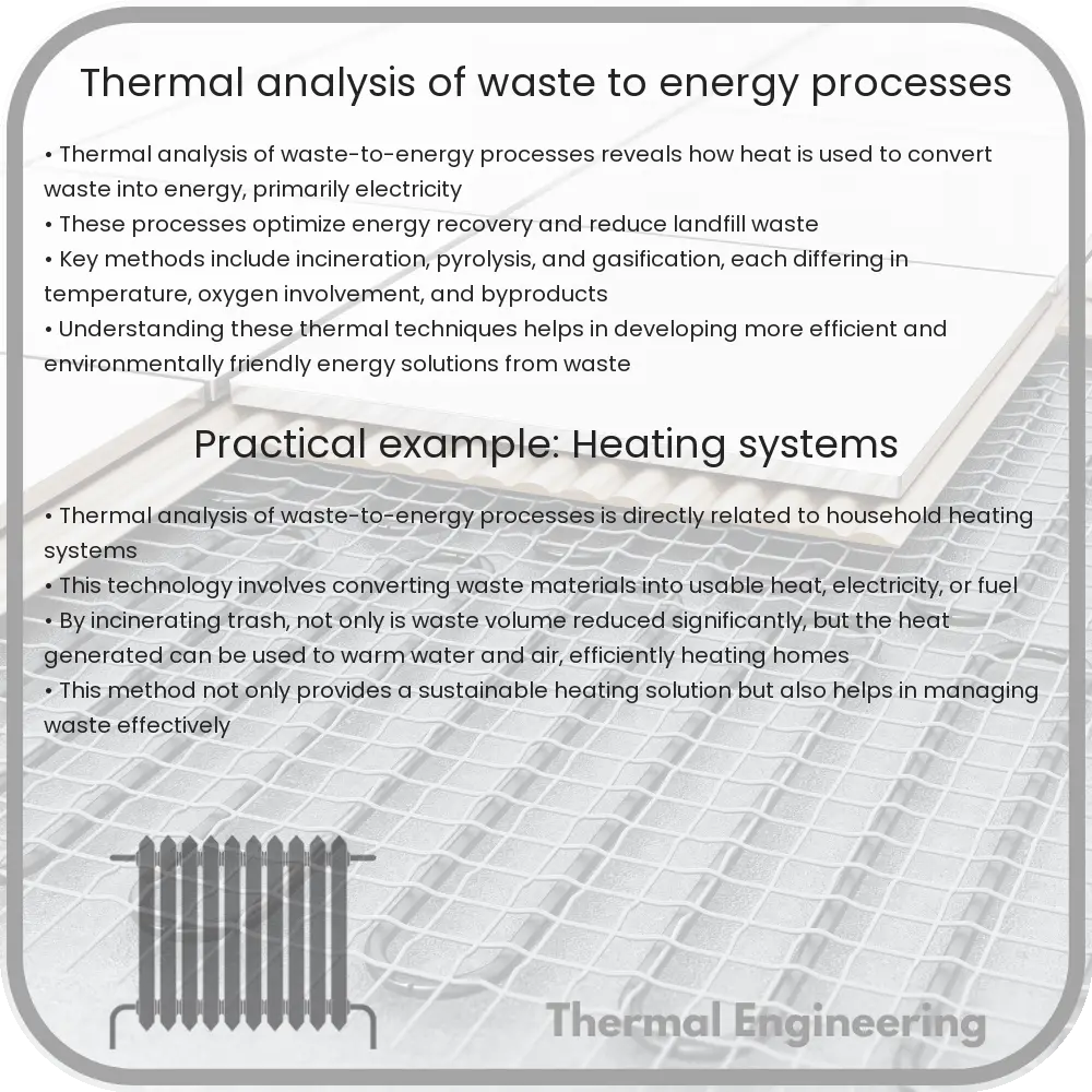
Thermal analysis of waste-to-energy processes

Understanding the role of thermal analysis in optimizing waste-to-energy processes for better efficiency and sustainability.

Thermal analysis of waste-to-energy processes

Thermal Analysis of Waste-to-Energy Processes

Transforming waste into energy through thermal technologies is a critical component of managing municipal solid waste and generating energy simultaneously. In this article, we explore the basics of thermal analysis in waste-to-energy (WtE) processes, focusing on the most common methods and their implications on energy production and environmental sustainability.

Understanding Waste-to-Energy Processes

Waste-to-energy (WtE) refers to various technological processes designed to convert either organic or inorganic waste materials into electricity, heat, or combustible fuels. Common technologies in this domain include incineration, gasification, and pyrolysis. The choice of technology impacts the energy recovery efficiency, pollutant emission, and the economic feasibility of the WtE plants.

Incineration

Incineration is the most established WtE process, where waste materials are completely combusted in the presence of oxygen, creating steam that usually drives a turbine to generate electricity. The thermal analysis of such processes focuses on optimizing the burning temperature to enhance efficiency and minimize harmful emissions. Generally, the temperatures in the incinerators range from 850°C to 1100°C. The efficiency of energy conversion in incineration can be expressed as:

Eeff = (Eoutput / Einput) * 100%

where Eoutput is the energy produced in the form of electricity or heat, and Einput is the energy content of the waste.

Gasification

Gasification involves converting carbonaceous materials into a synthetic gas (syngas) consisting of hydrogen and carbon monoxide. This conversion occurs in a controlled environment with limited oxygen. The thermal efficiency of gasification depends on maintaining high temperatures (between 700°C and 1400°C) and managing the reactor’s internal atmosphere to optimize syngas production and calorific value. Accurate thermal analysis ensures the reaction remains endothermic, requiring continuous heat input.

Pyrolysis

Pyrolysis is the thermal decomposition of materials at elevated temperatures (typically above 500°C) in the absence of oxygen. The products of pyrolysis include bio-oil, syngas, and char, all of which can be converted into energy. Thermal analysis in pyrolysis monitors the temperature profile and heating rate, which significantly influence the yield and quality of the outputs. Key considerations include minimizing the activation energy required for decomposition without resorting to excessive temperatures that may reduce the overall energy efficiency.

Thermogravimetric Analysis (TGA)

One pivotal method used in thermal analysis of WtE processes is Thermogravimetric Analysis (TGA), which measures the amount and rate of change in a material’s weight as a function of temperature or time under a controlled atmosphere. For WtE, this helps determine suitable temperatures for maximizing energy output while reducing residual waste.

  • Calorimetric Analysis: This involves measuring the heat involved in waste decomposition and transformation, giving insights into the energy potential of waste streams.
  • Mass Spectrometry: This is used alongside TGA to analyze the composition of gases produced during the thermal conversion processes, which informs adjustments needed for optimizing energy production and emission controls.

Environmental and Economic Implications

The thermal analysis of WtE processes is not only about maximizing energy efficiency but also about minimizing the environmental impact. Proper thermal control can reduce the formation of dioxins and other harmful emissions typically associated with high-temperature waste treatment. Economically, efficient thermal processes translate to higher net energy gains, which can significantly offset operation costs and contribute to the economic viability of WtE facilities.

In conclusion, thermal analysis plays a crucial role in optimizing waste-to-energy processes. It guides engineers in the selection of appropriate technologies and operational parameters, ultimately leading to more sustainable and economically viable waste management solutions.

5 Types of Heat Transfer in Combustion Processes

Explore the fundamental roles of conduction, convection, radiation, advection, and mass transfer in enhancing heat transfer efficiency in combustion processes.

5 Types of Heat Transfer in Combustion Processes

Understanding Heat Transfer in Combustion Processes

Heat transfer in combustion processes is a fundamental concept in the field of thermodynamics and plays a crucial role in various engineering applications, including power generation, automotive engines, and industrial furnaces. The efficiency of combustion systems heavily relies on the effectiveness of heat transfer mechanisms. There are five primary types of heat transfer in combustion processes: conduction, convection, radiation, advection, and mass transfer. Each type has unique characteristics and effects on how heat energy is distributed and used in combustion systems.

1. Conduction

Conduction is the transfer of heat through a solid material from one molecule to another without any movement of the material as a whole. In combustion chambers, heat conduction occurs in the walls and other solid components. The rate of heat conduction through a material is governed by Fourier’s law of heat conduction, which can be expressed as:

q = -k * A * (dT/dx)

  • q is the heat transfer rate.
  • k is the thermal conductivity of the material.
  • A is the cross-sectional area through which heat is flowing.
  • dx is the thickness of the material.
  • dT is the temperature difference across the material.

2. Convection

Convection is the transfer of heat by the movement of fluids (liquids or gases). In combustion processes, hot combustion gases transfer heat to cooler areas of the system or to surfaces such as heat exchanger tubes through convective motion. Convection can be natural (driven by buoyancy forces due to temperature differences) or forced (enhanced by external means such as fans or pumps). The convective heat transfer rate can be described by Newton’s law of cooling:

q = h * A * (Tsurface – Tfluid)

  • h is the heat transfer coefficient.
  • A is the area where convection occurs.
  • Tsurface is the temperature of the surface.
  • Tfluid is the temperature of the fluid.

3. Radiation

Radiation involves the transfer of heat in the form of electromagnetic waves, primarily infrared radiation, without any medium. This type of heat transfer is significant in high-temperature environments typical of combustion. The Stefan-Boltzmann law quantifies radiant heat transfer:

q = ε * σ * A * (T4)

  • ε is the emissivity of the surface (ranging from 0 to 1).
  • σ is the Stefan-Boltzmann constant (5.67 x 10⁻⁸ W/m2K4).
  • T is the absolute temperature of the surface.

4. Advection

Advection is the transport of heat by the bulk movement of a fluid. In combustion, this can occur when hot gases flow through ducts or when the flame itself moves, carrying energy from one location to another. Advection can also involve movements generated by external factors like wind or by the combustion process itself.

5. Mass Transfer

Though not a direct mode of heat transfer, mass transfer significantly influences combustion processes by including the movement of combustible species to the flame and the resulting products away from it. This movement can affect the temperature profiles and combustion efficiency. Mass transfer often collaborates with convection, where the motion of mass (fluid containing heat) contributes to heat distribution in a system.

Understanding these methods of heat transfer allows engineers to design more efficient combustion systems, optimize energy usage, and reduce emissions, ultimately leading to improved performance and lower environmental impacts.

4 Types of Convective Heat Transfer Enhancements

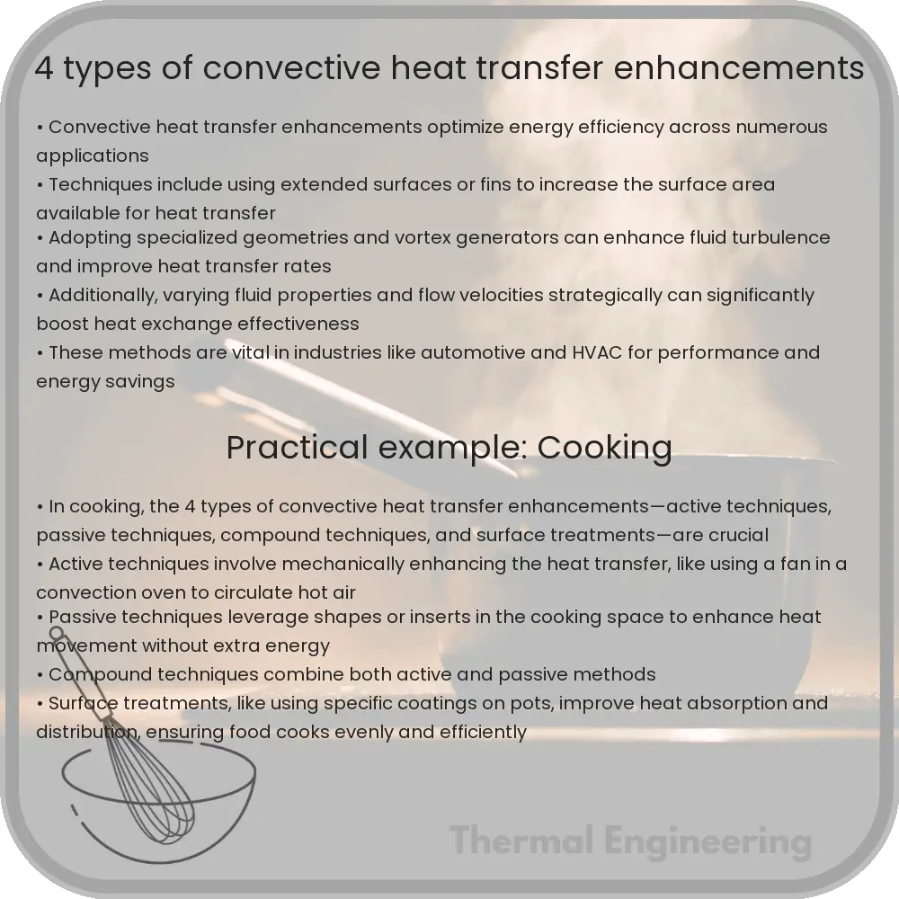
Understanding and optimizing convective heat transfer enhancements for improved efficiency in engineering applications.

4 Types of Convective Heat Transfer Enhancements

Introduction to Convective Heat Transfer Enhancements

Convective heat transfer is a fundamental concept in engineering, representing the transport of thermal energy between a physical boundary and a moving fluid. Enhancing convective heat transfer can significantly improve the efficiency of various thermal processes in automotive, aerospace, electronics cooling, and HVAC applications. There are several techniques to augment the heat transfer rate, and understanding these can be crucial for optimal design and efficient energy use.

1. Active Enhancement Techniques

Active techniques involve external energy inputs to increase the convective heat transfer rate. This may include mechanical aids, surface vibration, fluid vibration, and electrostatic fields. Active methods often result in higher heat transfer coefficients but at the cost of additional energy consumption.

  • Mechanical aids: Implementation of devices such as fans and stirrers that enhance the fluid motion relative to the heat transfer surface.
  • Surface vibration: Applying oscillatory motions to the surface can disturb the boundary layer, enhancing the heat transfer rate.
  • Fluid vibration: Oscillation of the fluid itself increases turbulence, thereby improving the thermal transport properties.
  • Electrostatic fields: Using electric fields can enhance heat transfer in dielectric fluids by influencing fluid motion through dielectrophoresis or electrohydrodynamics.

2. Passive Enhancement Techniques

Unlike active techniques, passive methods do not require any external energy. They typically involve modifications to the heat transfer surface or the addition of special additives to the fluid. These changes usually increase the effective surface area or disrupt the flow to enhance mixing.

  • Extended Surfaces: Incorporates fins or other geometric modifications to increase the surface area available for heat transfer.
  • Rough surfaces: Introducing roughness elements on the surface breaks up laminar sublayers and increases turbulence, which enhances heat transfer.
  • Displaced enhancements: Items like inserts or twisted tapes are used inside tubes to disrupt the core flow, increasing heat transfer effectiveness through better mixing.
  • Additives for fluids: The addition of nanoparticles or fibers to the fluid can significantly alter the thermal conductivity and viscosity, enhancing the convective heat transfer.

3. Compound Techniques

Compound techniques combine active and passive methods to benefit from both approaches. An example is the use of a stirrer (active) along with fins (passive) within a system. The synergy from such combinations often leads to more significant enhancement than the sum of individual effects.

4. Geometric Optimization

Optimizing geometry, from the shape of the heat exchanging surfaces to the entire heat exchanger configuration, is a subtle yet powerful way to enhance convective heat transfer. Tailoring geometry can involve:

  • Channel shaping: Modifying the channel geometry where the fluid flows can significantly affect flow patterns and heat transfer rates.
  • Pinch points: Designing narrow passages in heat exchangers to increase the velocity at certain points, enhancing the local heat transfer rates.
  • Swirl flow devices: Utilizing devices that induce a swirling motion in the fluid increases centrifugal forces and disrupts the boundary layer, hence increasing the heat transfer rate.

Conclusion

Enhancing convective heat transfer is pivotal in optimizing thermal systems, making them more energy-efficient and effective. Each of the methods discussed offers unique advantages and can be selected based on the application requirements, existing system design, and efficiency needs. By integrating these techniques thoughtfully, engineers can design more sophisticated and effective cooling and heating systems in various industrial applications.

8 Types of Thermal Imaging Techniques for Inspection

Learn about eight types of thermal imaging techniques used for effective inspection across various industries, including infrared thermography and cooled detectors.

8 Types of Thermal Imaging Techniques for Inspection

Understanding Thermal Imaging Techniques for Inspection

Thermal imaging, a technique that detects heat emitted by objects to create an image assembled from that data, is invaluable across various industries for inspection and monitoring purposes. This technology helps in identifying abnormal temperatures in mechanical equipment, electrical systems, and buildings, which are indicative of potential problems. Here are eight key types of thermal imaging techniques used for effective inspection:

1. Infrared Thermography

Infrared thermography is the most common thermal imaging technique. It involves the detection and measurement of infrared energy emitted from an object, converting it into a visible image that represents the temperature variations across the object’s surface.

2. Cooled Infrared Detectors

Cooled infrared detectors are highly sensitive imaging systems that require the detector elements to be cooled to low temperatures, often below 0°F (-18°C). This cooling significantly enhances their resolution and sensitivity, making them ideal for detecting very subtle differences in thermal radiation.

3. Uncooled Infrared Detectors

Contrary to cooled infrared detectors, uncooled detectors operate at ambient temperatures. These devices are simpler and more cost-effective while being sufficiently effective for a wide range of applications, such as building inspections, industrial maintenance, and security monitoring.

4. Active Thermography

Active thermography introduces an external energy source to induce thermal contrast. This technique can be particularly useful for materials inspection, subsurface defect detection, and composite evaluation. Sources of energy used include optical flash lamps, heaters, or ultrasound, which generate thermal responses that are then captured by infrared cameras.

5. Passive Thermography

Passive thermography relies solely on naturally occurring thermal energy from the inspected object itself, without any external stimulation. This method is commonly used in scenarios where the natural state of the object can provide sufficient thermal contrast, such as human body temperature screening.

6. Lock-in Thermography

Lock-in thermography is a variant of active thermography where a periodic thermal excitation (like a pulsing heat source) is applied to an object. The thermal camera measures the phase shift and amplitude of the object’s thermal response, which can indicate defects or material variations not visible to other imaging techniques.

7. Pulse Thermography

Pulse thermography involves heating the object’s surface with a short, high-energy pulse and observing the cooling process using an infrared camera. This method is effective in detecting features like corrosion, delamination, or other flaws in materials by examining the heat flow characteristics.

8. Flash Thermography

Flash thermography is a sub-type of pulse thermography where a flash lamp is used to deliver a short burst of energy to the surface of an object. The subsequent thermal patterns are analyzed to identify abnormalities.

Each of these thermal imaging techniques offers unique advantages based on the specific requirements of the inspection task. The choice of method can vary based on factors such as sensitivity needs, target operating conditions, spatial resolution requirements, and cost constraints. Understanding these different techniques enables professionals to select the most appropriate method for maintaining equipment reliability, safety, and operational efficiency.

7 Types of Drag in Fluid Dynamics and Aerodynamics

Learn about the different types of drag in fluid dynamics and aerodynamics, crucial for designing efficient vehicles and structures.

7 Types of Drag in Fluid Dynamics and Aerodynamics

Understanding Drag in Fluid Dynamics and Aerodynamics

Drag is a force that opposes the motion of an object through a fluid (liquid or gas). This force is crucial in the fields of fluid dynamics and aerodynamics, affecting everything from airplane efficiency to the performance of sports cars. There are several types of drag, each stemming from different physical phenomena. Understanding these can help in designing more efficient vehicles and structures. Below are seven key types of drag encountered in fluid dynamics and aerodynamics:

1. Form Drag (Pressure Drag)

Form drag arises due to the shape of the object moving through the fluid. It is influenced by how the air or liquid flows around the body, creating a wake region of low pressure behind it. The pressure difference between the front and the back of the object leads to this type of drag. Bulky, non-aerodynamic shapes experience higher form drag.

2. Friction Drag (Skin Drag)

Friction drag occurs due to the friction between the fluid and the surface of the moving object. This type of drag is influenced by the texture and material of the object’s surface. Smooth and streamlined surfaces reduce friction drag by allowing the fluid to flow more smoothly over the surface.

3. Induced Drag

Induced drag is particularly relevant in aerodynamics, especially noticeable in aircraft at lower speeds and high angles of attack, such as during takeoff and landing. It is associated with the generation of lift, and its occurrence is due to wingtip vortices that create a pressure difference over the wing. Reducing the wingtip vortices with design elements like winglets can decrease induced drag.

4. Wave Drag

Wave drag occurs when an object moves fast enough to create compression waves in the fluid, such as shock waves formed around aircraft flying at or above the speed of sound. This type of drag is predominant in supersonic and hypersonic flight and is a major factor in the design of high-speed aircraft.

5. Interference Drag

Interference drag happens when varying currents of air meet and interact around different parts of a structure. For example, where the wing meets the fuselage of an aircraft, these interactions can disrupt the flow of the fluid, increasing drag. Aircraft designers typically smooth the transition between different parts to minimize this effect.

6. Parasitic Drag

Parasitic drag is a category of drag that includes form, friction, and interference drag. It is called parasitic because it does not contribute to the functionality of the vehicle, particularly in generating lift in aircraft. This type of drag typically becomes more significant as the object’s speed increases.

7. Base Drag

Base drag is related to the aft end of a body moving through a fluid, commonly seen in vehicles with a blunt trailing edge. The high-pressure area in front of the body and the low-pressure wake behind combine to create this drag force. Aerodynamic tailoring, such as boat-tailing in rockets and cars, can reduce base drag.

  • Reducing Drag: Engineers work to optimize the design of vehicles and structures to minimize drag, thereby improving efficiency, speed, and fuel consumption. This is achieved through aerodynamic shaping, selecting appropriate materials, and incorporating technology such as active control surfaces and flow manipulation devices.
  • Impact of Drag: Understanding and controlling drag is essential not only in vehicles like cars, airplanes, and ships but also in sports, building design, and even in the environment pertaining to wind flow patterns around natural formations and man-made structures.

In summary, drag is a complex and multifaceted force that plays a critical role in fluid dynamics and aerodynamics. The various types of drag interact with one another, and their cumulative effect dictates the efficiency and performance of moving objects in a fluid environment. By comprehending and managing these different types of drag, significant advancements in technology and design can be realized.