Facebook Instagram Youtube Twitter

9 Types of Airflow Patterns in Environmental Control

Airflow patterns” are the varied ways air moves and is distributed in environmental control, influencing system efficiency and air quality.

9 Types of Airflow Patterns in Environmental Control

Understanding Airflow Patterns in Environmental Control

Airflow patterns play a critical role in environmental control systems within various settings like laboratories, industrial spaces, and climate control systems in buildings. These patterns affect everything from temperature regulation to air quality management. Understanding the different types of airflow can help engineers and technicians design more effective and efficient systems. Here, we explore nine common types of airflow patterns.

Laminar Flow

Laminar flow is characterized by smooth, parallel layers of air that move at uniform velocity. This type of airflow is utilized in settings requiring minimal interference and contamination, such as clean rooms and surgical theaters. The air moves in a consistent direction and speed, reducing the chance of cross-contamination.

Turbulent Flow

Contrasting laminar flow, turbulent flow involves irregular fluctuations and mixing. In this airflow pattern, velocity and direction vary at different points in the air stream. Turbulent flow is common in most real-world applications, including ventilation systems where enhanced mixing and distribution of air are needed.

Oscillating Flow

This type of airflow changes direction periodically, typically in a sinusoidal manner. Oscillating flows are useful in applications such as oscillating fans and cyclic ventilation systems where air distribution needs to be spread over a large area without the need for continuous directional airflow.

Plug Flow

In plug flow, all particles of the air move parallel to each other and move at the same speed. This type of flow occurs in ducts and channels where the air is forced to move together without much mixing across the cross-section. It’s similar to laminar flow but usually occurs at higher velocities.

Path Line Flow

Path line flow describes the trajectory that individual air particles trace as they move. This is particularly important for tracing the movement of contaminants or specific air packets within larger flow fields. It helps in understanding how substances disperse in a ventilated space.

Jets and Plumes

Air jets describe concentrated flows of air issued from a source into an environment, whereas plumes involve buoyancy-driven flow, like warm air rising from a heater. Both patterns are crucial in HVAC design, where targeted or natural air movement is necessary for effective environmental control.

Vortex Flow

Vortex flow occurs when air rotates around a central axis. This can happen naturally, as with tornadoes, or in engineered systems like cyclones used in industrial dust collection. The rotational movement helps in segregating and removing particulate matter from air streams.

Recirculating Flow

Recirculating airflow patterns are cycles where air is cooled, heated, or purified and then reintroduced into the same environment. This is common in building HVAC systems where maintaining a constant temperature and air quality efficiently is crucial.

Stack Effect

The stack effect is a natural process driven by temperature differences between the inside and outside of a building, leading to vertical air movement. Air within the building becomes warmer and less dense, rising and exiting through higher openings, while cooler air enters through lower openings. Understanding the stack effect is vital for designing effective natural ventilation and smoke management systems.

Each of these airflow patterns has distinct characteristics and applications in environmental control systems. By choosing the appropriate airflow pattern, engineers can optimize air distribution, energy consumption, and overall system effectiveness.
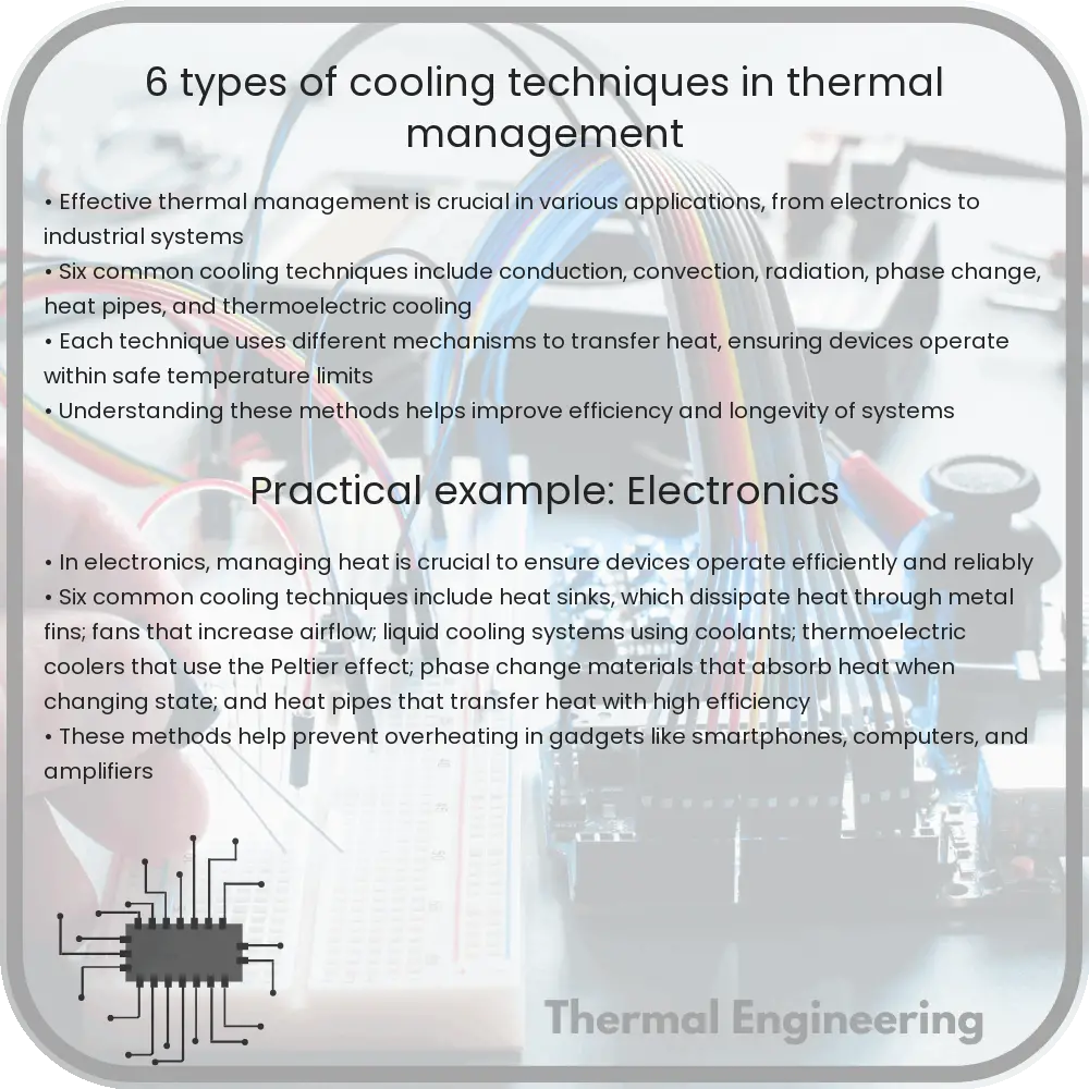
6 Types of Cooling Techniques in Thermal Management

This article delves into six crucial cooling techniques used in thermal management across various industries to ensure optimal operation and longevity of systems.

6 Types of Cooling Techniques in Thermal Management

Introduction to Cooling Techniques in Thermal Management

Thermal management is a critical aspect of engineering, particularly in electronics, automotive, aerospace, and HVAC systems, where efficient heat dissipation is crucial for reliable operation and longevity. Overheating can result in reduced performance, failures, and safety issues. This article explores six principal cooling techniques used across various industries to manage heat effectively.

1. Air Cooling

Air cooling is one of the simplest and most common methods used to dissipate heat. It involves the flow of air, often facilitated by fans or blowers, across a heated surface to lower its temperature. The effectiveness of air cooling depends on the air velocity, ambient temperature, and the properties of the air flow path.

  • Advantages: Low cost, simplicity, and minimal maintenance requirements.
  • Disadvantages: Limited cooling capability, which can be insufficient for highly dense or high power devices.

2. Liquid Cooling

Liquid cooling involves the circulation of a coolant in close proximity to hot components. The coolant absorbs heat from the component and then dissipates it through a radiator or heat exchanger. Liquids have a higher heat capacity and can remove heat more efficiently than air.

  • Advantages: More efficient in removing heat due to higher heat capacity of liquids.
  • Disadvantages: More complex installation, higher costs, and potential for leaks.

3. Heat Sinks

Heat sinks are passive cooling devices that increase the surface area in contact with the cooling medium, such as air or liquid. They are typically made from metals with high thermal conductivity, such as aluminum or copper. Heat sinks utilize fins or pins to enhance the heat transfer rate by convection.

  • Advantages: Simple, no moving parts, reliable, and cost-effective for moderate cooling needs.
  • Disadvantages: Effectiveness is limited by the ambient temperature and airflow; not suitable for extremely high heat fluxes.

4. Thermoelectric Cooling (Peltier Cooling)

Thermoelectric coolers operate on the Peltier effect, where heat is absorbed or released when an electric current passes through a junction of two different materials. This method can be used for precise temperature control.

  • Advantages: Provides both cooling and heating, precise temperature control, compact and no moving parts.
  • Disadvantages: Low energy efficiency and high cost in larger applications.

5. Phase Change Materials (PCMs)

PCMs absorb and release thermal energy during the process of melting and solidifying at a specific temperature. They are used to mitigate temperature fluctuations and manage transient thermal loads.

  • Advantages: Effective in stabilizing temperature variations and storing thermal energy.
  • Disadvantages: Integration and containment can be challenging; limited by the phase change temperature range of the material.

6. Spray Cooling

Spray cooling uses a sprayed, fine mist of coolant directly onto a hot surface, where it evaporates rapidly, taking away a significant amount of heat due to the latent heat of vaporization. This is often used in high-performance applications like power electronics and high-speed computing.

  • Advantages: Extremely efficient at removing high heat flux densities.
  • Disadvantages: Can be complex to implement, requires careful management of the coolant and can be expensive.

Conclusion

Choosing the right cooling technique in thermal management depends on a variety of factors including environmental conditions, space constraints, budget, and specific application needs. Understanding the advantages and limitations of each method provides a foundation for engineers to design more effective and efficient cooling solutions for any given application.

12 Types of Lubrication Systems in Fluid Mechanics

Explore the 12 common types of lubrication systems in fluid mechanics, vital for reducing friction in machinery.

12 Types of Lubrication Systems in Fluid Mechanics

Understanding Types of Lubrication Systems in Fluid Mechanics

Lubrication systems are crucial in mechanical engineering for reducing friction and wear between moving parts. Various systems have been developed to deliver lubricants like oil or grease effectively. Here’s a comprehensive look at the 12 common types of lubrication systems used in fluid mechanics:

1. Manual Lubrication

Manual lubrication systems require an operator to apply lubricant directly to parts of the machinery at regular intervals. This is practical for smaller or less complex machines where automated systems are not feasible.

2. Centralized Lubrication

Centralized systems deliver controlled amounts of lubricant to multiple points in a machine from a single, centrally located reservoir. This helps in efficiency and ensures consistent lubrication.

3. Automatic Lubrication

These systems automatically supply lubricant to parts when needed, based on timers or sensors, without human intervention. They are used in machines where continuous operation is critical.

4. Drip Feed Lubrication

In drip feed lubrication, oil is delivered to parts through drip feeders that control the rate of oil flow. Commonly used in spindle bearings and chains, it’s effective for precise lubrication.

5. Splash Lubrication

Splash lubrication uses the motion of parts within the machinery to splash oil from the sump onto other components. It is often found in internal combustion engines and transmission boxes.

6. Ring Lubrication

This system uses a ring that sits around a rotating shaft. The ring dips into the lubricant reservoir and picks up lubricant, which is then delivered to the shaft as it rotates.

7. Bath or Sump Lubrication

Here, parts of the machinery are partially submerged in a bath of lubricant, ensuring continuous contact with the oil. This method is frequently used for gears and bearings.

8. Pressure Lubrication

Pressure systems force lubricant through passages to the machinery’s components under pressure. This is vital for modern high-speed engines and machinery, providing reliable lubrication under various conditions.

9. Mist Lubrication

Mist or fog lubrication systems create a fine mist of oil that is carried directly to the lubrication points via air pressure. It’s particularly useful in environments where minimal lubricant application is desired.

10. Jet Lubrication

In jet lubrication, jets of oil are directed at fast-moving parts or bearings. The high speed of components helps in dispersing the oil evenly over the surfaces needing lubrication.

11. Recirculating Systems

These systems collect the used lubricant, filter it, and re-use it. Recirculating systems are economical and environmentally friendly as they maximize the utilization of the lubricant.

12. Gas Lubrication

Gas lubrication uses gases like air or inert gases as a lubricant. This type of lubrication is suited for very high-speed conditions where traditional liquids cannot be used effectively.

The choice of a lubrication system depends largely on the application, cost considerations, and maintenance requirements. Advances in technology continuously improve the effectiveness and efficiency of these systems, contributing significant improvements in the longevity and reliability of machinery.

7 Types of Buoyancy Effects in Fluid Dynamics

Learn about the seven types of buoyancy effects in fluid dynamics, including positive, negative, and neutral buoyancy, and their roles in engineering applications.

7 Types of Buoyancy Effects in Fluid Dynamics

Understanding the 7 Types of Buoyancy Effects in Fluid Dynamics

Buoyancy is a fundamental concept in fluid dynamics which describes how objects behave when submerged in a fluid. Whether it’s a ship floating on water or a hot air balloon rising in the air, buoyancy effects play a critical role. Let’s explore seven types of buoyancy effects and understand their applications and phenomena in fluid dynamics.

1. Positive Buoyancy

Positive buoyancy occurs when an object is less dense than the fluid in which it is submerged. As a result, the object will float or rise to the surface. This can be observed in boats, icebergs, and hot air balloons. The buoyant force, which is responsible for this, is calculated by the formula:

FB = ρ * V * g

where ρ is the density of the fluid, V is the volume of the fluid displaced by the object, and g is the acceleration due to gravity.

2. Negative Buoyancy

Negative buoyancy occurs when an object is denser than the fluid in which it is submerged, causing it to sink. This is crucial in applications such as submarine design and underwater pipelines. The object’s ability to sink is governed by the same buoyant force equation, but in this case, the weight of the object exceeds the buoyant force.

3. Neutral Buoyancy

Neutral buoyancy is achieved when the weight of the submerged object is exactly balanced by the buoyant force. This state is essential for underwater organisms like jellyfish and submarines when they wish to stay at a constant depth without floating upward or sinking downward.

4. Archimedes’ Principle

Archimedes’ principle is the fundamental law of buoyancy, stating that the buoyant force on an object is equal to the weight of the fluid it displaces. This principle is the basis for designing ships and understanding the floating and sinking of objects.

5. Compressibility Effects

In gases, compressibility effects can influence buoyancy significantly. As the pressure and temperature of the gas change, so does its density, affecting the buoyant force. This is particularly important in the case of balloons and airships, where altitude changes result in temperature and pressure variations.

6. Thermal Expansion

Thermal expansion refers to the change in volume of a fluid due to temperature changes, which affects buoyancy. For example, hot water is less dense than cold water. In engineering, this effect needs to be considered when designing systems that involve heating or cooling of fluids.

7. Salinity Effects

Salinity affects the density of water; salt water is denser than fresh water. This impacts the buoyancy of objects. Engineers must consider salinity variations when designing marine vessels or when performing operations in various water bodies, such as oceans versus rivers.

Buoyancy not only provides a fascinating glimpse into the principles governing fluid dynamics, but it also has practical implications in various engineering fields. By understanding the different types of buoyancy, engineers can design more effective and sophisticated systems that interact with fluids.

5 Types of Phase Change Materials for Thermal Storage

Learn about the different types of Phase Change Materials (PCMs) and their applications in thermal management across various industries.

5 Types of Phase Change Materials for Thermal Storage

Introduction to Phase Change Materials

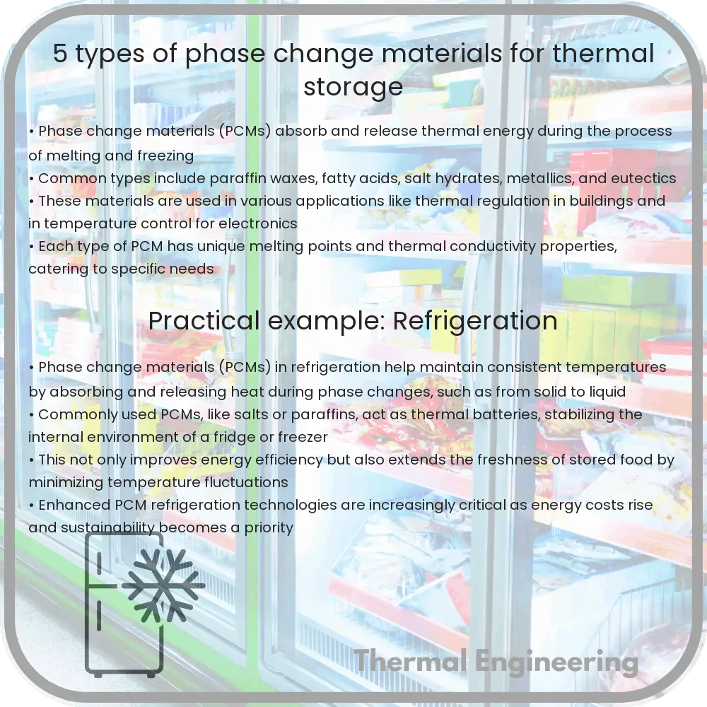
Phase Change Materials (PCMs) are substances with a high capacity for thermal energy storage, which absorb or release heat at a specific temperature during the phase change process. PCMs are used in various applications to maintain temperature stability such as in building materials, refrigeration, and electronic systems. Understanding the types of PCMs helps in selecting the right material for specific thermal management needs.

1. Organic PCMs

Organic phase change materials are typically made from paraffin or fatty acids. They are known for their reliability during repeated cycles of melting and freezing. Organic PCMs are non-corrosive, chemically stable, and can operate effectively in domestic and commercial cooling applications. However, their thermal conductivity is relatively low, which can be a limitation for rapid thermal response purposes.

  • Paraffin-based PCMs: Popular in thermal management, these materials have a melting point that can be adjusted by changing the carbon chain length.
  • Fatty acids: These are ideal for moderate temperature applications and offer minimal supercooling, contributing to a more consistent phase change process.

2. Inorganic PCMs

Inorganic phase change materials include salt hydrates and metallic solutions. These PCMs generally have higher latent heat storage capacity and thermal conductivity than organic PCMs. Challenges with inorganic PCMs include phase segregation and corrosion, which might require additional materials for encapsulation to enhance durability.

  • Salt Hydrates: Effective in storing heat at higher temperatures, salt hydrates are beneficial for industrial heat recovery processes.
  • Metallic PCMs: These are generally used in high-temperature applications such as in power plants and aerospace technology.

3. Eutectic PCMs

Eutectic PCMs are a blend of two or more materials that melt and solidify at a single, sharp melting point. Eutectics can be either organic, inorganic, or a combination of both. They are used when precise temperature control is needed, and they display a congruent melting and solidification behavior.

  • Organic-Organic Eutectics: These combinations often feature adjustable phase change temperatures for diverse applications.
  • Inorganic-Organic Eutectics: These provide a symbiotic balance, leveraging higher latent heat and enhanced thermal stability.

4. Bio-based PCMs

Recently, research has focused on bio-based PCMs due to their environmental benefits and renewable sources. These materials, such as biomasses and bio-derived fats, are biodegradable and less toxic, making them attractive for residential use and environmentally sensitive applications.

  • Bio-derived Fats: Similar to fatty acids, they offer good thermal storage capacity and lower environmental impact.
  • Biomass Materials: They are researched for their innate PCM properties and adaptability across different temperature ranges.

5. Composite PCMs

Composite PCMs are advanced materials that combine various types of PCMs with enhancing additives like graphene, carbon fibers, or metallic nanoparticles to improve thermal conductivity and overall performance. These composites aim to overcome the limitations of pure PCMs, such as suboptimal thermal response and cycling stability.

  • PCM-Enhanced Composites: These materials often show increased thermal conductivity and reduced supercooling.
  • Nano-enhanced PCMs: By integrating nanoparticles, these composites achieve better heat transfer efficiency and thermal stability.

Conclusion

Phase Change Materials play a crucial role in thermal management solutions across various industries. Whether organic, inorganic, eutectic, bio-based, or composite, each type of PCM offers unique properties and benefits suitable for specific applications. As technology advances, the efficiency and application scope of PCMs are expected to expand, offering new possibilities for energy conservation and thermal regulation.

3 Types of Heat Pipes for Efficient Heat Transfer

Learn about heat pipes, highly efficient thermal conductors that leverage evaporation and condensation to transfer heat across various engineering applications.

3 Types of Heat Pipes for Efficient Heat Transfer

Introduction to Heat Pipes

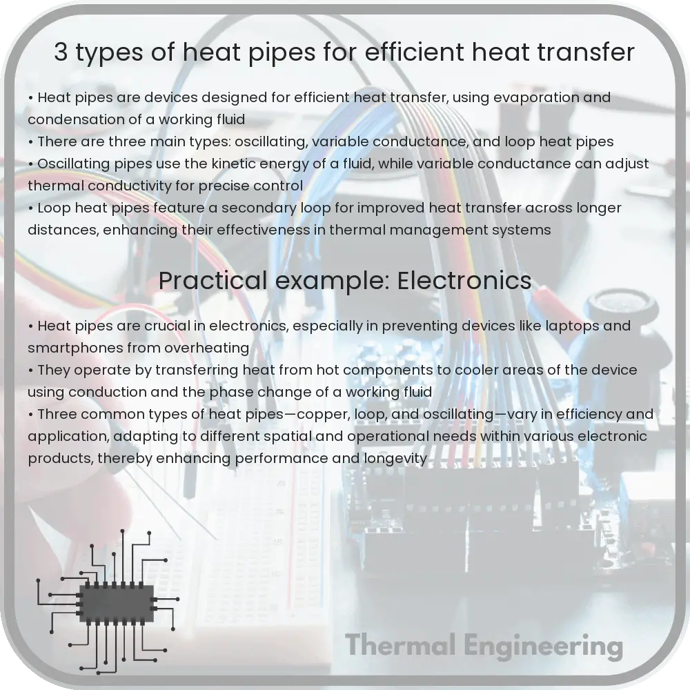
Heat pipes are highly efficient thermal conductors used in various engineering applications to transfer heat. They operate on the principles of evaporation and condensation, and are particularly useful in situations where conventional cooling methods are inadequate.

Basic Principle of Heat Pipes

A heat pipe typically consists of a sealed hollow tube made of a thermally conductive metal such as copper or aluminum. The tube is partially filled with a working fluid, which at operating temperature is in equilibrium between liquid and vapor phases. When one part of the pipe is exposed to a heat source, the fluid absorbs heat and transforms into vapor. The vapor travels along the pipe to a cooler area, where it condenses back into a liquid, releasing the latent heat. The liquid then returns to the hot end by capillary action through a wick structure lining the inner walls of the pipe, or by gravity in simpler setups, thus completing the cycle.

Types of Heat Pipes

There are several types of heat pipes designed to accommodate various applications and operational exigencies. Below are three common types:

1. Thermosyphon

Thermosyphons work on the principle of gravity-driven return of liquid and do not employ a wick structure. The evaporator section (heated section) is positioned below the condenser section (cooled section), letting gravity pull the condensate back to the evaporator. This type of heat pipe is simple in design and particularly effective in vertical applications where the heat source is at the bottom.

2. Wick-based Heat Pipes

In wick-based heat pipes, a porous wicking material is utilized to transport the working fluid from the condenser back to the evaporator against gravity. This allows the heat pipe to operate in any orientation, making it versatile for a variety of applications including aerospace and electronic cooling systems. Common wicking structures include:

  • Sintered powder metal
  • Mesh screens
  • Grooved surfaces

3. Loop Heat Pipes

Loop heat pipes (LHPs) are a more advanced type of heat pipe that offer high-efficiency heat transfer over long distances and against gravitational forces. They consist of an evaporator, condenser, transport lines, and a compensation chamber that controls the operating pressure of the system and thus the overall temperature range. LHPs are particularly effective in systems where precise thermal control is required, such as satellites and spacecraft.

Applications of Heat Pipes

Due to their efficient heat transfer capabilities, heat pipes find applications across a broad spectrum of industries. They are used in:

  • Electronics cooling (PCs, servers, etc.)
  • Energetic systems (solar panels, heat exchangers)
  • Aerospace (thermal management systems for satellites)
  • Industrial processes where heat recovery is crucial

Conclusion

Heat pipes are a vital technology in thermal management systems, providing highly efficient solutions for transferring heat over various distances and orientations. Whether through simple thermosyphons, versatile wick-based designs, or advanced loop heat pipes, this technology continues to evolve and expand its application scope. Understanding the different types of heat pipes and their specific uses helps in optimizing thermal management strategies across several fields of engineering.

10 Types of Water Turbines for Hydroelectric Power

Learn about the 10 types of water turbines used for efficient hydroelectric power generation, each suited to specific hydraulic conditions.

10 Types of Water Turbines for Hydroelectric Power

Understanding the 10 Types of Water Turbines Used in Hydroelectric Power Generation

Water turbines are a critical component in hydroelectric power systems, harnessing the energy of flowing water to generate electricity. The type of turbine used can significantly affect the efficiency and capacity of a hydroelectric power plant. This article explores ten types of water turbines commonly employed in the industry.

1. Pelton Wheel

The Pelton wheel, named after engineer Lester Allan Pelton, is an impulse turbine used predominantly for high head, low flow water sources. It features buckets attached to the rim of the wheel where jets of water strike and push the wheel, creating rotational energy which is then converted into electricity.

2. Turgo Turbine

Similar to the Pelton wheel but designed to handle a higher water flow at a slightly lower head, the Turgo turbine is an impulse type with inclined buckets that allows water to pass through the turbine after striking it, facilitating more effective use of water’s energy.

3. Crossflow (Banki-Michell) Turbine

A crossflow turbine features a drum-like rotor with blades that water flows through twice, first from the outside and then from the inside. This type is particularly suited for low head and high flow scenarios and is valued for its simplicity and tolerance to debris.

4. Francis Turbine

The Francis turbine is a common reaction turbine, versatile in its application for medium head and flow conditions. The water flows radially inward and then axially upward, driving the runner and converting hydraulic energy into mechanical energy efficiently.

5. Kaplan Turbine

Designed for low head and high flow applications, the Kaplan turbine features adjustable blades, allowing for operational flexibility and optimization according to varying water flow conditions. It’s a propeller-type reaction turbine that efficiently converts the kinetic energy of flowing water into mechanical energy.

6. Propeller Turbine

Similar to the Kaplan but typically with fixed blades, the propeller turbine is also well-suited for installations with high water flow and low head. The simplicity of the design is beneficial for reducing construction and maintenance costs.

7. Bulb Turbine

The bulb turbine integrates a Kaplan turbine into a streamlined bulb shape to minimize disruption in water flow, commonly used in tidal and low-head river installations. It’s excellent for sites where a compact, integrated design is necessary.

8. Straflo Turbine

The Straflo or tubular turbine features a generator integrated around the periphery of the turbine runner, optimizing the flow path of water through the turbine and generator assembly. It’s especially used in low head applications with a straight flow path.

9. Tyson Turbine

A variation of the traditional water wheel, the Tyson turbine is a modern adaptation that allows for more efficient energy capture in low head sites without significant environmental disturbances, often used in small scale and micro hydro installations.

10. Gorlov Helical Turbine

Developed for use in flowing water with no significant head, the Gorlov helical turbine has a vertical axis and a twisted blade design reminiscent of DNA strands. It’s commonly employed in tidal and small river installations to capture energy from flowing water effectively regardless of the direction.

Conclusion

Choosing the right type of water turbine is essential for optimizing the efficiency and effectiveness of a hydroelectric power system. Each turbine type is designed to perform best under specific hydraulic conditions and has its own set of advantages and suitability. Understanding these turbines helps in the architectural planning and operational performance of hydro energy projects globally.

Passive solar heating solutions

Learn about passive solar heating, a sustainable method to harness solar energy for building warmth without mechanical systems.

Passive solar heating solutions

Understanding Passive Solar Heating Solutions

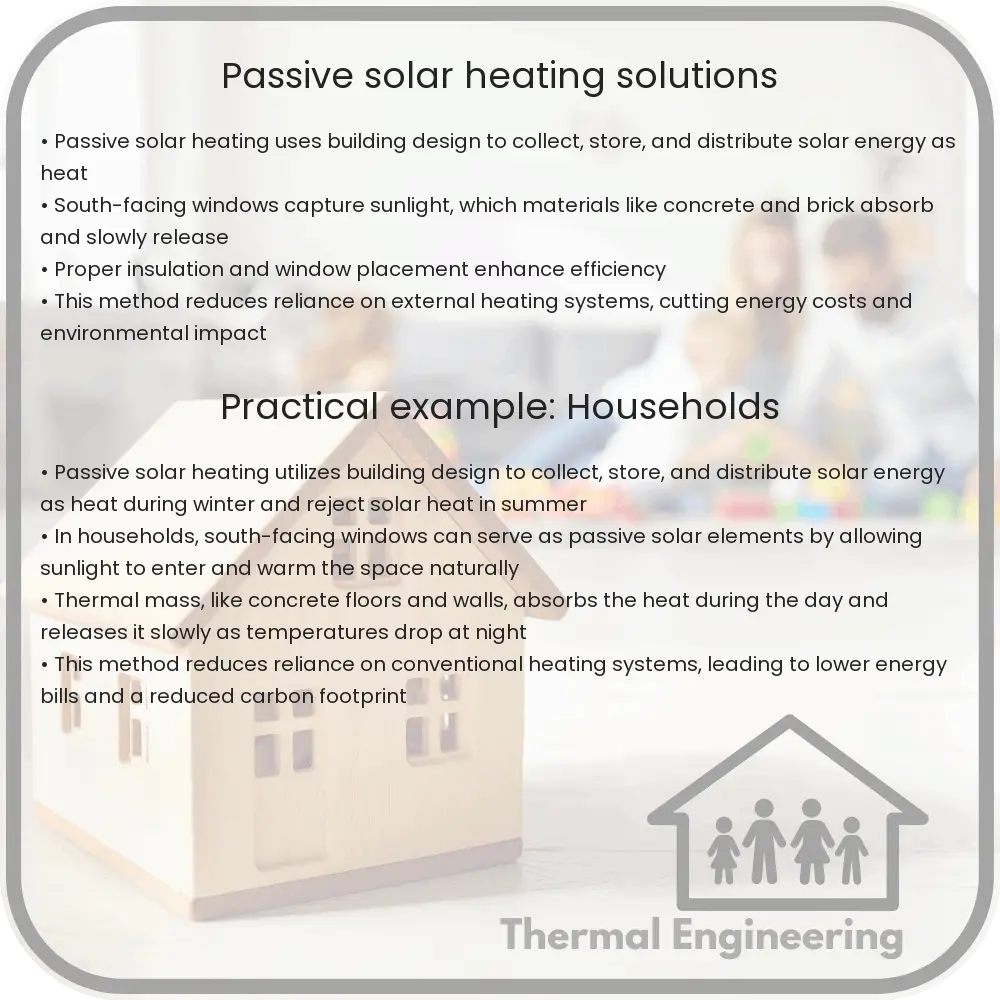
Passive solar heating is a method used to collect, store, and distribute solar energy in buildings without the use of active mechanical systems. It is a simple and sustainable approach to reduce dependency on fossil fuels, lower energy costs, and decrease carbon footprint. The primary aim of passive solar heating is to make the best use of natural sunlight to provide effective heating solutions. Understanding the basic principles and techniques of this system can help in designing buildings that are both energy-efficient and environmentally friendly.

Key Principles of Passive Solar Heating

There are three main principles integral to the effective design of passive solar heating systems:

  • Solar Collection: This is the process of capturing solar radiation. The design includes strategically placed windows and materials that absorb and store heat. South-facing windows are commonly used in the northern hemisphere to maximize solar gain during the winter months.
  • Heat Storage: Thermal mass materials such as stone, brick, or concrete are used within the building to store heat during the day and gradually release it overnight, maintaining a comfortable temperature range.
  • Distribution: Heat distribution is managed by the natural convection and conduction within the building. This can be enhanced through design elements such as open floor plans and thermal siphoning.

Components of Passive Solar Heating Systems

Several architectural components and materials play roles in optimizing the efficiency of passive solar heating:

  1. Windows: Specially designed to maximize solar gain, windows are crucial for collecting solar energy. Typically, areas with colder climates might use glazing designed to minimize heat loss.
  2. Thermal Mass: Materials like thick walls made of concrete or brick absorb heat during the day. The heat is then released slowly, helping to warm the building during cooler nights or cloudy days.
  3. Insulation: Proper insulation is vital in keeping the heat inside and preventing it from escaping. Insulation needs to be especially effective on the roof and north-facing walls.
  4. Sunspaces: These are glass-covered rooms or enclosed porches which capture heat in the space itself, acting as a buffer zone by reducing heat loss and distributing warmth into the building.

Benefits and Limitations

Passive solar heating systems offer significant benefits, making them increasingly popular in sustainable building designs:

  • Reduced Energy Costs: By maximizing the use of natural sunlight, these systems can significantly reduce reliance on artificial heating, thereby cutting energy costs.
  • Environmental Impact: Passive solar heating reduces the use of fossil fuels, contributing to a reduction in greenhouse gas emissions.
  • Low Maintenance: Unlike active solar heating systems, passive systems require minimal mechanical parts, resulting in lower maintenance costs and fewer points of failure.

However, there are limitations that must be considered:

  • Climate Dependency: The effectiveness of passive solar heating relies heavily on the local climate. In areas with long, cloudy winters, the performance may not meet the heating requirements.
  • Overheating Risk: Without careful design, buildings can overheat during the warmer months. Proper ventilation and shading are necessary to mitigate this.
  • Initial Cost and Design Complexity: Integrating passive solar design may require a higher initial investment and detailed planning during the design phase of a building.

Conclusion

Passive solar heating represents a blend of ancient architectural wisdom and modern engineering techniques. While it offers substantial benefits in terms of energy efficiency and ecological balance, successful implementation depends on thoughtful design and understanding of local climatic conditions. For those seeking sustainable and cost-effective building solutions, passive solar heating systems can be an excellent option to explore.

Temperature distribution in large-scale composting

Learn how temperature distribution impacts large-scale composting, affecting decomposition rates and compost quality.

Temperature distribution in large-scale composting

Understanding Temperature Distribution in Large-Scale Composting

Large-scale composting is an essential process for converting organic waste into valuable soil amendments. One of the critical factors influencing the efficiency of composting and the quality of the final product is the temperature distribution within the compost pile. This article explores the factors that affect temperature distribution, its impact on decomposition rates, and strategies for optimal temperature management.

Factors Affecting Temperature Distribution

Temperature distribution in a compost pile is influenced by several interconnected factors:

  • Aeration: Oxygen supply affects microbial activity. Proper aeration helps maintain aerobic conditions, fostering thermophilic activity that increases temperature.
  • Moisture Content: Moisture is crucial for microbial survival but excess water can lead to anaerobic conditions, reducing heat generation.
  • Particle Size: Smaller particles increase the surface area for microbes but can compact, impeding airflow and heat transfer.
  • Carbon to Nitrogen Ratio (C:N): An optimal C:N ratio (about 30:1) is vital for sustaining microbial activity and heat production.

Thermal Dynamics in Composting

Composting generates heat through the metabolic processes of microorganisms that decompose organic matter. The temperature of a compost pile typically passes through several phases:

  1. Mesophilic phase: This initial phase occurs as microorganisms begin to break down readily decomposable materials, causing the pile temperature to rise to about 20-45°C.
  2. Thermophilic phase: Temperatures can soar to between 45-75°C, enhancing the decomposition of more complex materials like proteins and fats.
  3. Cooling and maturation phases: As the availability of decomposable material decreases, temperatures gradually fall, allowing for the colonization of fungi and actinobacteria that further break down fibrous materials.

The spatial temperature distribution within the compost pile can be highly variable, influenced by external ambient conditions, pile insulation, and internal biochemical activity. Hotspots, where temperatures are significantly higher than the surrounding material, are common and can lead to uneven compost maturation.

Monitoring and Managing Temperature

Effective management of temperature distribution in a compost pile involves:

  • Regular Temperature Monitoring: Using temperature probes at various depths and locations to gather data on the internal conditions of the pile.
  • Turning the Pile: Mechanical turning helps redistribute heat and moisture throughout the pile, homogenizing the microbial habitat.
  • Moisture Adjustment: Adding water or dry matter to balance the moisture content, ensuring optimal microbial activity and heat production.
  • Ventilation: Enhancing airflow through manual or mechanized aeration to support aerobic decomposition and prevent overheating.

Thermal imaging and computational models are also employed to visualize and predict heat distribution, offering a more detailed analysis that can guide composting operations.

Concluding Thoughts

Temperature control and monitoring play pivotal roles in maximizing the efficiency and outcome of large-scale composting operations. Understanding and managing the complex thermal dynamics of compost piles not only aids in producing higher quality compost but also in ensuring environmental compliance and sustainability. By fine-tuning these parameters, operators can greatly improve the degradation process, turning organic waste into a resource rather than a liability.

Overall, the study and optimization of temperature distribution within composting setups serve as a cornerstone for advancing waste management practices and enriching soil health globally.

4 Types of Heat Sink Materials for Electronics

Explore the properties and applications of common heat sink materials such as aluminum, copper, zinc, and graphite in electronics.

4 Types of Heat Sink Materials for Electronics

Understanding Heat Sink Materials in Electronics

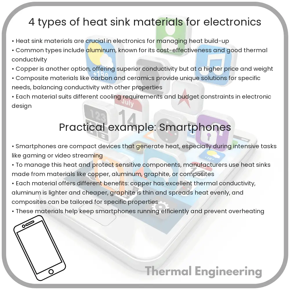
Heat sinks play a crucial role in maintaining the operational efficiency of electronic devices by dissipating excess heat. The material used in the construction of a heat sink significantly affects its performance. Here’s a look at the four most common types of heat sink materials and their distinct characteristics.

1. Aluminum

Aluminum is perhaps the most widely used material for heat sinks due to its good thermal conductivity and lightweight properties. It has a thermal conductivity of approximately 235 W/m*K, making it an excellent choice for a wide range of electronic applications. Aluminum heat sinks are typically manufactured using extrusion, casting, or machining processes.

  • Advantages: Lightweight, corrosion-resistant, and relatively inexpensive.
  • Applications: Used in CPUs, GPUs, and power transistors.

2. Copper

Copper has superior thermal conductivity than aluminum, rated at about 400 W/m*K. This makes it an excellent material for heat sinks that require rapid heat dissipation. Despite its effectiveness, copper is heavier and more expensive than aluminum, which can limit its use in some applications.

  • Advantages: Excellent thermal conductivity and antimicrobial properties.
  • Applications: High heat flux applications and precision cooling devices.

3. Zinc

Zinc heat sinks are less common but are used where cost, durability, and additional weight are not a major concern. Zinc’s thermal conductivity is significantly lower than aluminum and copper, around 120 W/m*K, but it offers excellent corrosion resistance, making it suitable for harsh environments.

  • Advantages: Corrosion resistance and good damping properties.
  • Applications: Typically found in automotive and consumer electronics subjected to harsh conditions.

4. Graphite

Graphite is a newer material in the field of heat sink technology, known for its unique anisotropic thermal properties. While it can have a thermal conductivity as high as 1950-4000 W/m*K along the basal plane, perpendicular to the plane it is much lower. This directional conductivity can be harnessed effectively in applications requiring heat spreading capabilities.

  • Advantages: Lighter than copper and aluminum, excellent thermal conductivity in specific directions.
  • Applications: LED lighting, power amplifiers, and high-frequency electronics where weight and space are critical.

Conclusion

Choosing the right heat sink material is pivotal in designing efficient electronic devices. Each material offers a balance of thermal performance, weight, and cost, affecting the electronic device’s overall performance and durability. Engineers must consider these factors when selecting a material for their heat sink applications to ensure optimal performance and longevity of electronic components.