Facebook Instagram Youtube Twitter

8 Types of Flow Meters in Fluid Dynamics

Comprehensive guide to the various types of flow meters used to measure fluid dynamics in different engineering applications.

8 Types of Flow Meters in Fluid Dynamics

Introduction to Flow Meters in Fluid Dynamics

Flow meters are essential devices used to measure the flow rate or quantity of a gas or liquid moving through a pipe. The choice of a flow meter depends on specific application requirements such as the nature of the fluid, flow rate, accuracy needed, and the environment in which the meter will operate. Here’s an overview of eight common types of flow meters used in various engineering fields related to fluid dynamics.

1. Differential Pressure Flow Meters

Differential pressure (DP) flow meters measure flow rate by inducing a pressure drop across a flow restriction element and calculating flow rate based on the pressure differential. One common example is the orifice plate, where the fluid flow is constricted through a thin plate with a hole in it, causing a drop in pressure across the plate. The flow rate is proportional to the square root of the pressure differential.

The basic formula used is: Q = C * A * (√(P1 – P2)), where:

  • Q is the flow rate,
  • C is the discharge coefficient,
  • A is the orifice area,
  • P1 and P2 are the upstream and downstream pressures respectively.

2. Magnetic Flow Meters

Also known as mag meters, these devices measure the flow rate of fluid that conducts electricity. The meter applies a magnetic field to the flow tube which results in a voltage signal being induced across the fluid. The voltage is directly proportional to the flow rate. Magnetic flow meters do not have any moving parts and are ideal for wastewater applications or any dirty liquid that is conductive or water-based.

3. Ultrasonic Flow Meters

Ultrasonic flow meters utilize sound waves to determine the velocity of a fluid flowing in a pipe. There are two primary types: transit-time and Doppler flow meters. Transit-time meters measure the time it takes for an ultrasonic pulse to travel from one transducer to another, which will vary with the flow velocity of the fluid. Doppler meters, on the other hand, exploit the Doppler effect, where the frequency of the ultrasound wave is shifted depending on the velocity of the flowing fluid.

4. Turbine Flow Meters

Turbine flow meters have a turbine wheel placed in the flow of fluid that rotates at a speed proportional to the flow rate. This rotation can be detected and converted into a flow measurement. Turbine meters offer high accuracy and can be used in a variety of fluid applications but are mostly used in water, petrochemical, and aerospace industries.

5. Positive Displacement Flow Meters

As the name suggests, positive displacement (PD) flow meters measure the volumetric flow rate by capturing fluid in compartments and counting the number of times these compartments are filled and emptied. This type of meter is very accurate for measuring the flow of viscous fluids or lubricating fluids and is highly reliable in industrial applications.

6. Vortex Flow Meters

Vortex flow meters work based on the von Kármán Vortex Street principle. Fluids passing by a bluff body in the meter generate vortices. The frequency of these vortices is proportional to the flow velocity. Vortex meters are robust and suitable for measuring steam, gases, and medium to high-viscosity fluids.

7. Thermal Mass Flow Meters

Thermal mass flow meters are utilized primarily for the measurement of low viscosity gases. They operate either by heating the fluid and measuring the temperature change upstream and downstream or by measuring the cooling effect of the fluid as it flows past a heated sensor. The rate of heat transfer is directly related to the mass flow of the fluid.

8. Coriolis Flow Meters

Coriolis flow meters directly measure the mass flow and the density of a fluid by using the Coriolis effect. The fluid is passed through a vibrating tube; the mass flow rate is measured from resulting changes in the vibration of the tube. Coriolis meters are highly accurate and are used in a wide range of chemical and pharmaceutical applications.

Conclusion

Each type of flow meter has its unique strengths and applications. Engineers select flow meters based on factors such as accuracy requirements, fluid characteristics, and environmental conditions. Understanding these differences can help in choosing the right flow meter for optimal performance and accuracy in measuring fluid dynamics.

6 Types of Thermal Barriers for Fire Protection

Learn about thermal barriers in fire protection, their crucial roles, and various types used to safeguard lives and property.

6 Types of Thermal Barriers for Fire Protection

Understanding Thermal Barriers in Fire Protection

Thermal barriers play a crucial role in fire protection engineering by limiting the spread of heat and flames during a fire, thus safeguarding both human lives and property. These barriers are designed to resist high temperatures and thermal conductivity, providing essential protection in various building structures and fire-prone areas. Below, we explore six common types of thermal barriers used for fire protection.

1. Fire-Resistant Wallboard

Fire-resistant wallboards are commonly used in constructing ceilings and interior walls. Made from materials such as gypsum and reinforced with fibers like fiberglass or mineral wool, these wallboards are designed to withstand fire and prevent the passage of flames and smoke. They are typically rated for fire resistance, with common ratings including 30, 60, 90, and 120 minutes, indicating how long they can resist a standard fire test.

2. Intumescent Coatings

Intumescent coatings are a form of passive fire protection. These special paints expand significantly when exposed to high temperatures, forming an insulating char layer that protects the structural members beneath. Applied to steel structures, wooden beams, and walls, intumescent coatings are often used in buildings and offshore facilities where maintaining the integrity of the structure during a fire is paramount.

3. Firestops

Firestops are critical in sealing gaps around electrical cables, pipes, and other penetrations through fire-rated walls and floors. Made from various materials like silicone, intumescent products, and mineral fibers, firestops expand when exposed to high temperatures, filling the gaps and preventing the spread of fire and smoke between different sections of a building.

4. Fire Doors

Fire doors are designed to resist the spread of fire within a building or into adjacent areas. Constructed from a combination of materials including timber, steel, gypsum, and glass, fire doors are integrated with intumescent strips along the edges that expand in the event of a fire, sealing the door against the door frame. The effectiveness of fire doors is rated by their ability to withstand fire for a specified duration, typically ranging from 30 to 120 minutes.

5. Fire-Retardant Blankets and Curtains

Fire-retardant blankets and curtains are made from materials that resist ignition or slow the spread of flames. They are often used as temporary or portable barriers against fire in various settings, such as theaters, schools, and industrial sites. These barriers not only prevent direct contact with flames but also reduce heat transfer, helping to control the temperature and spread of fire.

6. Fire-Resistant Glass

Fire-resistant glass is designed to provide a barrier against smoke, flames, and heat while offering visibility and light transmission. This type of glass is typically made by sandwiching a layer of fire-resistive gel between layers of tempered glass. The gel becomes opaque and expands when exposed to fire, providing a thermal barrier. Fire-resistant glass types are rated by the amount of time they can effectively withstand exposure to fire, generally ranging from 30 to 120 minutes.

In conclusion, understanding the different types of thermal barriers is essential for effective fire protection in engineering. Each type of barrier offers unique properties and applications, together forming an integrated approach to controlling fire and limiting its destructive impact on buildings and occupants. By combining these technologies, engineers can design safer, more resilient structures capable of withstanding the harsh realities of fire exposure.

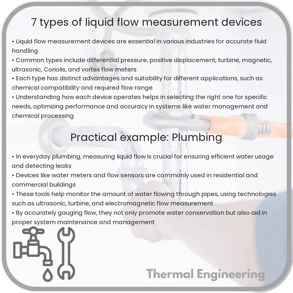
7 Types of Liquid Flow Measurement Devices

Learn about seven types of liquid flow measurement devices used in various industries to ensure accurate liquid management.

7 Types of Liquid Flow Measurement Devices

7 Types of Liquid Flow Measurement Devices

Liquid flow measurement is crucial in many industries ranging from water treatment to chemical processing. There are several types of devices designed to accurately measure the flow of liquids. Each type uses a different principle and technology suitable for varying flow conditions and fluids.

1. Differential Pressure Flow Meters

Differential pressure flow meters work by measuring the pressure drop over an obstruction inserted in the flow path. The most common forms include orifice plates, flow nozzles, and Venturi tubes. The flow rate can be calculated using Bernoulli’s principle, which relates the pressure differential to the fluid velocity and the pipe diameter. The formula used for calculating flow rate Q can be expressed as:

Q = C * A * sqrt(ΔP / ρ)

  • C – discharge coefficient
  • A – area of the orifice
  • ΔP – pressure drop
  • ρ – fluid density

2. Electromagnetic Flow Meters

Electromagnetic flow meters operate based on Faraday’s law of electromagnetic induction. They are ideal for measuring the flow of electrically conductive liquids without any obstruction in the flow path. The voltage generated by the fluid as it flows through a magnetic field is proportional to the flow velocity. Therefore, the flow rate can be calculated by measuring this voltage.

3. Ultrasonic Flow Meters

Ultrasonic flow meters use sound waves to determine the flow rate of a liquid. They can be configured in either a transit-time or a Doppler shift version. Transit-time ultrasonic flow meters measure the time difference between sound pulses traveling upstream and downstream. The Doppler shift version measures the frequency shift of an ultrasonic signal when it is reflected off suspended particles or gas bubbles in motion within the liquid.

4. Turbine Flow Meters

Turbine flow meters have a turbine wheel placed in the flow stream. The flowing fluid impinges on the turbine blades, causing the wheel to spin at a rate proportional to the fluid velocity. Sensors detect the rotational speed and convert it into a flow rate measurement.

5. Positive Displacement Flow Meters

Positive displacement flow meters divide the incoming fluid into discrete volumes and count these volumes over time. They provide extremely accurate measurements for a wide variety of fluids, making them suitable for applications requiring precise flow measurements, like in fuel dispensing and batch processes.

6. Coriolis Flow Meters

Coriolis flow meters are distinguished by their ability to measure both mass flow and density of a liquid, providing a direct mass flow measurement. These meters function by vibrating a tube through which the fluid passes. Changes in the vibration frequency or phase shift are measured and related to mass flow rate.

7. Vortex Flow Meters

Vortex flow meters measure the vortices generated by a fluid as it passes around a bluff body embedded in the flow stream. The frequency of vortex shedding is directly proportional to the flow rate. These meters are well-suited for high-temperature and high-pressure flow measurements.

Each type of liquid flow measurement device offers specific advantages and limitations, making them more or less suitable for different applications, operational environments, and fluid characteristics. Understanding these can help in selecting the most appropriate meter for a given application.

5 Types of Conduction Heat Transfer Methods

Learn about the five types of conduction heat transfer, including Fourier’s Law, steady state, transient, linear, and radial conduction.

5 Types of Conduction Heat Transfer Methods

Understanding the 5 Types of Conduction Heat Transfer

Heat transfer by conduction occurs when thermal energy transfers from one object to another through direct contact. This fundamental concept is crucial in disciplines like engineering and environmental science. In this article, we’ll explore the five primary methods of conduction heat transfer, offering insights into how each process works and where it typically occurs.

1. Fourier’s Law of Heat Conduction

Named after the French physicist Jean Baptiste Joseph Fourier, this law forms the basis for understanding thermal conduction. Fourier’s law states that the rate at which heat transfers through a material is proportional to the negative gradient in the temperature and to the area through which the heat is flowing. The mathematical representation is:

q = -k * A * (dT/dx)

  • q is the heat transfer rate (in watts, W)
  • k is the thermal conductivity of the material (in watts per meter Kelvin, W/m*K)
  • A is the cross-sectional area perpendicular to the heat flow (in square meters, m2)
  • dT/dx is the temperature gradient in the direction of the heat flow (in Kelvin per meter, K/m)

2. Steady State Conduction

Steady state conduction refers to a process in which the temperature field in the conducting body does not change over time. In practical terms, it means that the heat flow into any region of the material is exactly balanced by the heat flow out. This scenario often occurs in building insulation and thermal engineering designs where maintaining consistent temperature profiles is crucial.

3. Transient Conduction

Unlike steady state conduction, transient conduction occurs when the temperature field within an object changes over time. This type of conduction is significant during the heating or cooling phase of objects, and its analysis typically requires solving the heat equation using time-dependent boundary conditions and initial conditions.

4. Linear Conduction

Linear conduction refers to heat transfer through a homogeneous rod or slab in which the thermal conductivity is independent of the temperature. The distance over which the heat flow occurs significantly affects the efficiency and speed of the heat transfer, making it a critical factor in applications such as heat sinks and thermal barriers.

5. Radial Conduction

Radial conduction is a type of heat flow that occurs outward in a radial direction from a central axis. This method is particularly important in cylindrical and spherical objects like pipelines, rods, or tanks used in chemical and power plants. Managing radial conduction is essential for ensuring the efficiency and safety of such systems.

Understanding these various methods of conductive heat transfer is pivotal for engineers and designers when they choose materials, design objects, and build systems that handle high temperatures or require efficient thermal management. Each method provides a framework to address different industrial challenges and innovate in heat-sensitive applications.

9 Types of Fluid Couplings in Mechanical Systems

Detailed exploration of nine types of fluid couplings, highlighting their roles in transferring torque and enhancing mechanical system efficiency.

9 Types of Fluid Couplings in Mechanical Systems

Understanding Fluid Couplings: 9 Types in Mechanical Systems

Fluid couplings are fundamental components used extensively in mechanical engineering to transmit rotating mechanical power. They use a fluid to create a hydrodynamic connection which allows for the transfer of torque between the shafts. This article explores nine common types of fluid couplings used in various mechanical systems, significantly enhancing efficiency and control.

1. Hydraulic Torque Converter

A hydraulic torque converter is a type of fluid coupling that adds a variable aspect to torque conversion, making it ideal for automotive transmissions. This converter not only transmits power but also provides torque multiplication at low speeds, improving the vehicle’s acceleration.

2. Fluid Coupling

Often referred to simply as a “fluid coupling,” this basic type relies on two sets of vanes, one connected to the input and the other to the output shaft. It uses hydraulic oil to transmit power and provides a smooth start with reduced shock loads in power transmission systems.

3. Constant-fill Fluid Coupling

The constant-fill fluid coupling maintains a constant volume of fluid within the system. It is widely used in applications requiring stable operation and a predictable torque response, such as in conveyor systems and industrial processing equipment.

4. Variable Speed Fluid Coupling

This type allows the adjustment of torque and speed by varying the amount of hydraulic fluid or by changing the geometry of the passage through which the fluid moves. Variable speed fluid couplings are essential in applications requiring speed control and load variation, commonly found in fans and blowers.

5. Delayed Fill Fluid Coupling

In delayed fill fluid couplings, the chamber is initially empty, and fills gradually during operation. This design facilitates a controlled start-up by initially reducing torque, which can be critical in reducing mechanical stresses and energy usage in heavy machinery startups.

6. Slip Type Fluid Coupling

The slip type is designed to allow a certain amount of slip between input and output speeds, permanently or under specific conditions, providing a cushioning effect to reduce mechanical shocks and system stresses.

7. Lock-up Fluid Coupling

This variant incorporates a mechanical lock-up arrangement that can bypass the fluid coupling under certain operating conditions, directly connecting the input to the output. Lock-up fluid couplings are advantageous in applications where efficiency is critical at high speeds.

8. Hybrid Fluid Coupling

Hybrid fluid couplings combine the features of fluid couplings with other coupling types, like electromagnetic or mechanical clutches, to enhance functionality and adaptability across a broader range of operational conditions.

9. Pump and Motor Couplings

These are specialized fluid couplings where one part acts as a pump and the other as a motor. This type is particularly useful in complex hydraulic machinery and systems requiring variable torque and speed adjustments, such as in aerospace and heavy industry applications.

Fluid couplings are pivotal in modern engineering, providing a versatile and reliable method for managing torque and protecting mechanical systems. By understanding the distinct types and their specific applications, engineers can select the perfect fluid coupling type that best fits the operational and efficiency needs of their projects.

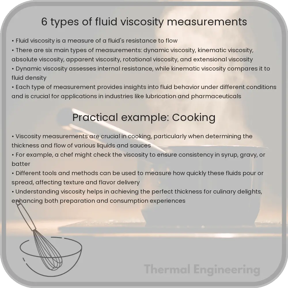
6 Types of Fluid Viscosity Measurements

Learn about fluid viscosity, its importance in engineering, and various methods to measure it, including capillary, rotational, and falling ball viscometers.

6 Types of Fluid Viscosity Measurements

Understanding Fluid Viscosity and Its Measurement

Viscosity is a fundamental property of fluids which describes the internal resistance offered by a fluid to flow. This property is critical in various engineering and scientific applications as it influences how fluids behave under different conditions and in different systems. Measuring viscosity allows engineers and scientists to understand and predict how fluids will perform in processes ranging from simple piping to complex fluid dynamics in machinery. There are several ways to measure the viscosity of a fluid, each suited for different types of fluids and applications.

1. Capillary Viscometer

A capillary viscometer, often referred to as a U-tube viscometer, measures the viscosity of a fluid by observing the flow time of a known volume of fluid through a narrow capillary tube under the influence of gravity. This method is based on the Poiseuille’s law, which relates the flow rate, the pressure drop, the viscosity, and the dimensions of the tube. Capillary viscometers are widely used due to their simplicity and effectiveness in measuring the viscosity of Newtonian fluids.

2. Rotational Viscometer

An essential tool for determining the viscosity of non-Newtonian fluids is the rotational viscometer. In this method, a spindle or rotor is submerged in the fluid, and the resistance to the rotation, caused by the fluid’s viscosity, is measured. As the spindle rotates, the torque required to overcome the viscous drag provides a measure of the fluid’s viscosity. Rotational viscometers can accommodate a wide range of viscosities and are particularly useful for fluids whose viscosity changes under shear stress, like paints and lubricants.

3. Falling Ball Viscometer

The falling ball viscometer technique involves measuring the time it takes for a ball to fall under gravity through a fluid in a vertical tube. According to Stokes’ law, the terminal velocity of the falling ball is related to the fluid viscosity. The resistance provided by the fluid to the falling ball is proportional to the viscosity. This method is suitable for transparent fluids where the motion of the ball can be observed easily.

4. Vibrational Viscometer

Vibrational viscometers measure viscosity by observing the damping of a vibrating element immersed in the fluid. The damping effect exerted by the fluid is indicative of its viscous nature. These viscometers are particularly useful for fast and continuous measurements of fluid viscosity in process control and industrial applications.

5. Brookfield Viscometer

A specific type of rotational viscometer is the Brookfield Viscometer, which utilizes spring-driven rotation to measure fluid viscosity. It is especially popular in industries for its reliability and repeatability. The device calculates viscosity by measuring the torque on the spindle driven by a motor at selectable speeds. The Brookfield Viscometer is versatile, accommodating a variety of spindle shapes and sizes to adapt to different fluid viscosities.

6. Saybolt Viscometer

Primarily used for the petroleum industry, the Saybolt Viscometer measures the viscosity by recording the time it takes for a fixed volume of fluid to flow through a narrow tube at a controlled temperature. The Saybolt Viscometer provides readings in Saybolt Universal Seconds (SUS), which can be converted to standard viscosity units. This viscometer is particularly useful for quality control and assurance in the production and refining of oil.

Each of these viscosity measurement methods offers unique benefits and is suitable for specific types of fluids and applications. Understanding how these methods work and where they are best applied can lead to more accurate and effective handling of fluids in both industrial and research settings.

10 Types of Cryogenic Cooling Methods and Applications

An in-depth exploration of cryogenic cooling, detailing methods like Joule-Thomson and Brayton Cycles, and its diverse applications from scientific research to industrial uses.

10 Types of Cryogenic Cooling Methods and Applications

Understanding Cryogenic Cooling: Methods and Applications

Cryogenic cooling refers to the process of cooling materials, components, or environments to extremely low temperatures, typically below -150 degrees Celsius (-238 degrees Fahrenheit). This field is essential in various scientific, medical, and industrial applications. Here, we explore ten prominent cryogenic cooling methods and their practical applications.

Types of Cryogenic Cooling Methods

  • Joule-Thomson Cooling: This method involves the adiabatic expansion of a gas that results in cooling. When gas at a high pressure is allowed to expand to a lower pressure, it cools itself down as it does work on its surroundings.
  • Brayton Cycle: In this method, gas is compressed, cooled in a heat exchanger, and then expanded to produce cooling. This cycle is often used in liquefying gases such as helium and hydrogen.
  • Stirling Cycle: Similar to the Brayton cycle, but with a regenerative heat exchanger which improves the thermal efficiency. It is widely used in cryocoolers.
  • Gifford-McMahon Cycle: A variation of the Stirling cycle that uses a displacer to provide regenerative cooling. Commonly employed in cryopreservation and MRI machines.
  • Pulse Tube Refrigerators: This involves reducing the temperature via a heat exchanger followed by an expansion process in the tube, which lacks moving mechanical parts, thus reducing maintenance.
  • Dilution Refrigerators: These are used to achieve temperatures very close to absolute zero, working by mixing helium-3 and helium-4 isotopes.
  • Magnetic Cooling: Based on the magnetocaloric effect, this method uses a magnetic field to align the magnetic dipoles of atoms to decrease temperature.
  • Adiabatic Demagnetization: This cools a salt by first magnetizing it at a low entropy state and then demagnetizing it isothermally.
  • Thermoacoustic Cooling: Uses sound waves in a pressurized gas to generate cooling through compression and expansion cycles. It has potential applications in environmentally-friendly refrigeration technology.
  • Closed Cycle Cryopump: Employed typically in vacuum systems, this involves the condensation of gases and vapors at cryogenic temperatures to create a vacuum.

Applications of Cryogenic Cooling

  1. Medical Applications: Used in cryosurgery and cryopreservation, where biological specimens are preserved at cryogenic temperatures.
  2. Industrial Applications: In cutting-edge manufacturing processes, including enhancing the properties of metals and for the storage of liquefied gases.
  3. Food Industry: Implementing cryogenic freezing for rapid freezing of food, which preserves the texture and nutritional content.
  4. Scientific Research: Essential in superconductivity experiments and quantum computing, where low temperatures are crucial.
  5. Aerospace: Used in space simulations and testing equipment exposed to the extreme cold of outer space.
  6. Electronics: For cooling high-performance computer chips and large-scale data centers to enhance efficiency and performance.
  7. Energy Sector: In the liquefaction of natural gas, which makes transportation and storage more efficient.
  8. Environmental Monitoring: Cryogenic cooling is critical in collecting and analyzing air samples, especially volatile compounds, at remote locations.

The diversity of cryogenic cooling methods is integral to furthering innovations and maintaining essential services in many high-tech industries. This makes the study and development of more efficient and practical cryogenic technologies a continually evolving and exciting field in science and engineering.

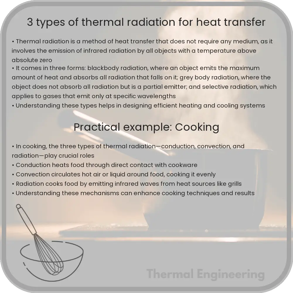
3 Types of Thermal Radiation for Heat Transfer

Learn about thermal radiation and its role in heat transfer, including blackbody radiation, selective radiation, and environmental radiation.

3 Types of Thermal Radiation for Heat Transfer

Understanding Thermal Radiation for Heat Transfer

Thermal radiation is one of the principal mechanisms of heat transfer, involving the emission of electromagnetic waves by all bodies possessing a temperature greater than absolute zero. Unlike conduction and convection, radiation does not require any medium for heat transfer. This phenomenon can be observed in everyday life, such as the warmth felt from the sun or a fire. Thermal radiation is crucial in many engineering applications including, heating, cooling, and energy systems. Here, we explore three important types of thermal radiation relevant to engineering applications: blackbody radiation, selective radiation, and environmental radiation.

1. Blackbody Radiation

Blackbody radiation represents the idealized form of thermal emission. A black body is an idealized physical body that absorbs all incident electromagnetic radiation, regardless of frequency or angle of incidence. The amount and wavelength of the radiated energy from a black body are functions of only the body’s temperature, described by Planck’s law.

Mathematically, the power emitted per unit area of a black body (emissive power, Eb) at a given temperature T is given by the Stefan-Boltzmann Law:

Eb = σT4

where σ (sigma) is the Stefan-Boltzmann constant (approximately 5.67 × 10⁻⁸ W/m2K4). This relationship underscores how emissive power increases with the fourth power of the absolute temperature, indicating that hotter objects emit more radiation energy at a much faster rate than cooler ones.

2. Selective Radiation

Unlike a black body, real materials do not absorb and emit radiation uniformly at all wavelengths. These objects are known as selective radiators. Selective radiators can emit and absorb energy more efficiently at some wavelengths than at others. The efficiency is defined by an object’s emissivity (ε), which is the ratio of the energy emitted by the object to the energy emitted by a black body at the same temperature.

Selective radiators are particularly important in engineering applications involving thermal insulation and solar heat absorption. For example, materials with high emissivity close to 1, like black paint, are used for solar heating applications because they absorb most of the incident solar radiation, converting it to heat.

3. Environmental Radiation

Environmental radiation refers to the thermal radiation exchange between objects and their surroundings. Unlike isolated blackbody or selective radiation, environmental radiation involves complex interactions between multiple bodies at different temperatures. The net radiation heat transfer between two objects can be calculated considering their individual emissivities, temperatures, and the absorptivity of their surroundings.

The net radiative heat transfer Q between two bodies can be described by the following equation:

Q = ε12σA(T14 – T24)

where ε12 is the effective emissivity between the two bodies, A is the area through which radiation is exchanged, T1 and T2 are the absolute temperatures of the bodies. This equation highlights the impact of environmental conditions and the nature of surface interactions on the radiative heat transfer process.

In conclusion, understanding the different types of thermal radiation is essential for optimizing heat transfer in various engineering systems. By manipulating parameters such as emissivity and understanding the nature of environmental radiation, engineers can design more efficient heating, cooling, and insulation systems tailored to specific environmental conditions and operational needs.

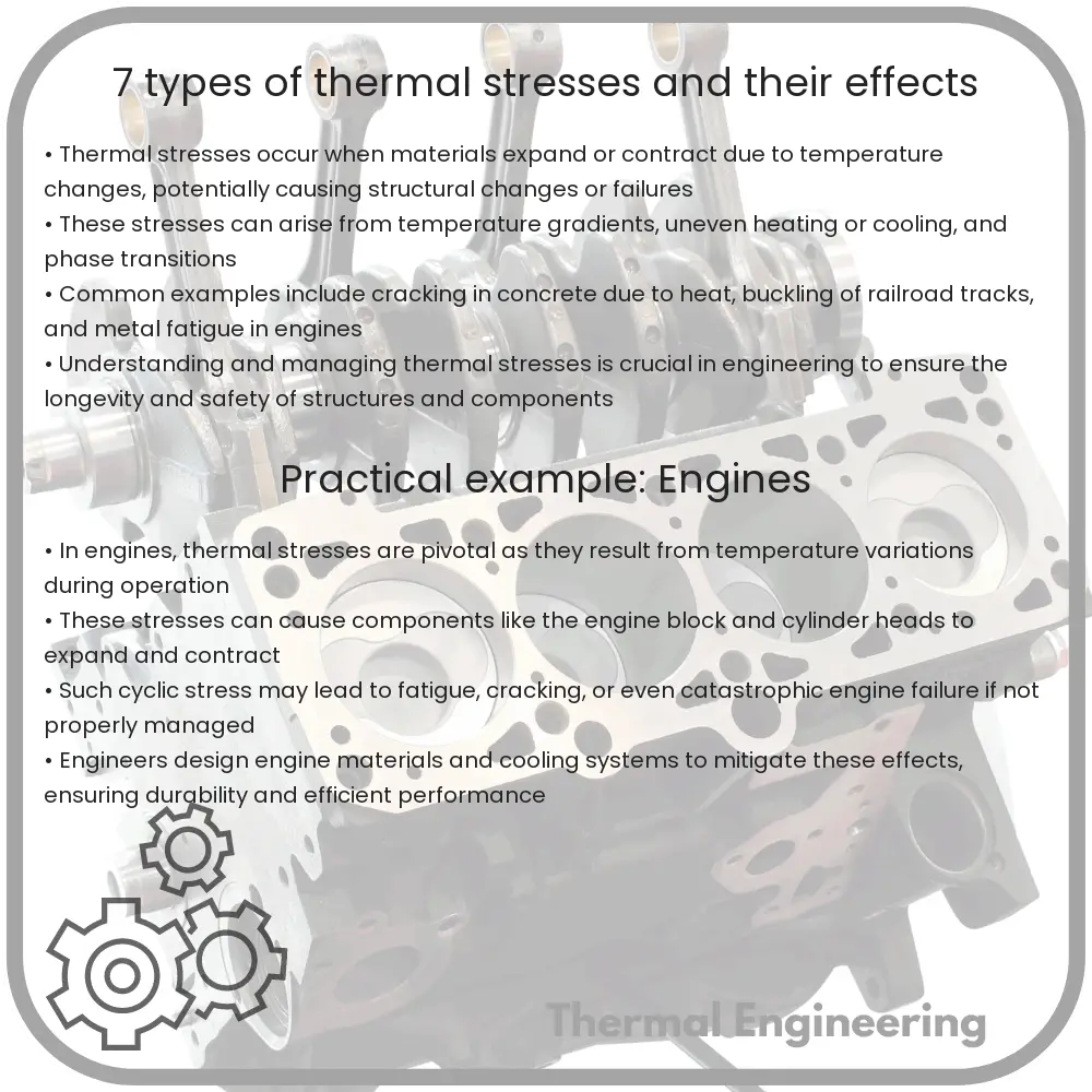
7 Types of Thermal Stresses and Their Effects

Learn about thermal stresses, their types, and their impacts on materials and structures due to temperature changes.

7 Types of Thermal Stresses and Their Effects

Understanding Thermal Stresses: Types and Effects

Thermal stress occurs in materials when temperature changes lead to expansion or contraction, which in turn causes stress due to the restraint provided by the surrounding environment or the material’s own constraints. Different materials have unique responses to temperature changes, influenced by their thermal expansion coefficients, structural constraints, and environmental conditions. This article explores seven key types of thermal stresses and discusses the impacts they can have on materials and structures.

1. Uniform Thermal Expansion or Contraction

Uniform thermal expansion or contraction occurs when a material heats or cools uniformly, causing it to change size uniformly. If the material is unrestrained, this typically does not cause stress. However, if the material is partly or fully constrained, stress can develop because part of the structure wants to expand or contract but is held back by supports or other parts of the structure.

2. Differential Thermal Expansion

Differential thermal expansion happens when different parts of a material or different connected materials heat or cool at different rates. This is particularly common in composite materials or in structures composed of different materials, each with distinct thermal expansion coefficients. Stresses develop due to the mismatch in expansion or contraction rates, potentially leading to warping, buckling, or even cracking.

3. Thermal Shock

Thermal shock results when a material experiences a sudden change in temperature. Rapid heating or cooling leads to abrupt expansions or contractions that the material can’t uniformly distribute across its volume or structure quickly enough. This sudden, uneven change can create severe localized stresses, leading to failures like cracking, especially in brittle materials.

4. Thermal Cyclic Stress

Thermal cyclic stress is caused by repeated and variating cycles of heating and cooling. Each cycle induces expansion and contraction, and the repeated nature of these cycles can lead to material fatigue. Over time, this stress can weaken the material, causing cracks to form and propagate, ultimately leading to structural failure.

5. Gradient Thermal Stress

Gradient thermal stress occurs when there are temperature gradients within the material. Heated surfaces expand while cooler interior regions of the material may not expand as much or as quickly, leading to stress across the material. This type of stress is a common concern in electronic components and other high-heat applications.

6. Thermal Strain Due to External Constraints

This type of thermal stress arises when external constraints (such as supports or foundations) prevent a structure from expanding or contracting freely as the temperature changes. Even a uniform temperature change can induce stress when movement is restricted by these external forces.

7. Phase Change Induced Stresses

Some materials undergo phase changes at certain temperatures (like water freezing or melting), which can significantly change their volume. If these changes occur while the material is confined or under external pressures, the volume change can induce considerable thermal stresses. This is commonly seen in pipelines with fluids that freeze or in structures exposed to fluctuating temperatures that cross the phase change threshold.

Conclusion

Recognizing and understanding these types of thermal stresses is critical in the design and material selection process for engineering applications. Effective management of thermal stresses can lead to safer, more reliable, and longer-lasting products and structures. Engineers often employ various mitigation strategies, including choosing materials with compatible thermal expansion properties, designing to accommodate expected temperature changes, and using thermal barriers or insulation to manage temperature extremes.

9 Types of Centrifugal and Axial Compressors

Learn about the different types of centrifugal and axial compressors used in various industrial applications.

9 Types of Centrifugal and Axial Compressors

Understanding the Types of Centrifugal and Axial Compressors

Centrifugal and axial compressors are critical components in various industrial applications, including HVAC systems, refrigeration, and turbochargers in automotive engines. Understanding the different types of these compressors can help you appreciate how they are tailored to meet specific requirements in engineering and technology. Here, we explore nine common types, categorized under centrifugal and axial compressors.

Centrifugal Compressors

Centrifugal compressors increase the pressure of a gas by converting angular momentum transmitted from a rotating impeller. These are widely used for their robustness and ease of maintenance in gas turbines, oil refineries, and chemical plants.

  • Single-Stage Centrifugal Compressor: This contains only one impeller. It is suitable for applications where a moderate increase in pressure is sufficient.
  • Multi-Stage Centrifugal Compressor: Uses multiple impellers, arranged in series, to progressively increase the pressure of the gas. It’s more efficient for achieving higher pressures.
  • Integrally Geared Centrifugal Compressor: Features several impellers driven by a single gearbox, allowing each impeller to operate at its optimal speed. Ideal for applications needing versatility and high performance.
  • High-Speed Centrifugal Compressor: Operates at very high speeds to achieve a substantial pressure increase, often used in the automotive and aerospace industries.

Axial Compressors

Axial compressors are typically used in high-flow, high-speed scenarios such as in jet engines and large gas turbines. They operate by accelerating the air through a series of rotor and stator blades, increasing its pressure gradually with each stage.

  • Low-Pressure Axial Compressor: Designed for applications where a large volume of air needs to be compressed at relatively low pressure.
  • High-Pressure Axial Compressor: Capable of achieving very high pressures, suitable for aerospace applications, particularly in jet engines.
  • Adjustable Stator Axial Compressor: Features adjustable stator blades that can vary their angle to match airflow conditions, enhancing efficiency over a range of operating conditions.

Specialized Compressors

Beyond the basic configurations, there are specialized types of compressors designed to address niche applications or enhance certain operational aspects.

  • Transonic Compressor: Operates at speeds around the speed of sound. It’s specially designed to handle the complexities of airflow undergoing a transition from subsonic to supersonic.
  • Supersonic Compressor: Operates at speeds greater than the speed of sound, and mostly used in specialized military applications needing very high compression ratios and efficiency.
  • Mixed-Flow Compressor: Combines features of both axial and centrifugal compressors for applications requiring medium pressure increase but with higher efficiencies.

Each type of compressor offers unique benefits and is suited for specific industrial applications. By selecting an appropriate compressor type, engineers can optimize performance, efficiency, and reliability in their systems.

Conclusion

Understanding the different types of centrifugal and axial compressors is crucial for anyone involved in the design or maintenance of systems where these components are used. Each type presents specific advantages and is suitable for particular applications, ensuring optimal performance across various industrial sectors.