Facebook Instagram Youtube Twitter

Thermal optimization of 3D printed structures

Explore thermal optimization in 3D printing to enhance structure integrity and functionality.

Thermal optimization of 3D printed structures

Understanding Thermal Optimization in 3D Printed Structures

The field of 3D printing, or additive manufacturing, has revolutionized the production of complex geometries and custom items. However, one critical aspect often encountered during the design and fabrication process is thermal optimization. This concept involves managing the thermal behavior of a 3D printed structure to ensure structural integrity, functionality, and longevity.

Importance of Thermal Optimization

Thermal optimization in 3D printed structures is crucial for several reasons:

  • Material Properties: Different materials have different responses to heat. Optimizing thermal properties helps in reducing stress and deformation caused by thermal expansion or contraction.
  • Operational Efficiency: Components subjected to high temperatures need to maintain their shape and strength. Effective thermal management can increase the reliability and efficiency of these components.
  • Safety: Preventing overheating in critical parts can significantly reduce the risk of failure and potential hazards associated with excess temperature.

Strategies for Thermal Optimization

Several strategies can be employed to ensure effective thermal management in 3D printed structures:

  1. Material Selection: Choosing materials with favorable thermal properties that match the specific requirements of the application.
  2. Design Modification: Altering design features such as thickness, geometry, and surface area to enhance heat dissipation or retention depending on the desired outcome.
  3. Use of Thermal Interface Materials (TIMs): Incorporating materials that can manage heat transfer between surfaces to improve thermal conductivity and reduce thermal resistance.

Thermal Simulation in Design Process

Thermal simulations play a vital role in the optimization process. Simulation tools can predict how a part will react to thermal loads and identify potential issues like stress concentration and warping. This predictive capability allows engineers to make informed decisions and iterate designs without the need for extensive physical testing.

Case Study: Engine Components

Consider the scenario of designing a 3D printed engine component subjected to high thermal loads. Using materials like high-temperature polymers or metal alloys could be crucial. Additionally, the design would benefit from simulations that help determine the most effective geometry for heat dissipation, such as incorporating fins or hollow sections.

An optimization might involve iterative redesigns based on simulation outcomes, testing different geometries to see which offers the best balance between thermal performance and structural strength. For example, altering the thickness of the walls or changing the layout of internal supports could significantly affect the heat flow paths within the component.

Conclusion

Thermal optimization in 3D printed structures is a complex but essential part of the design and manufacturing process in many engineering applications. By choosing appropriate materials, adjusting design parameters, and using advanced simulation tools, engineers can create safer, more efficient, and reliable products. As 3D printing technology continues to evolve, the integration of these strategies will increasingly become a standard practice, pushing the boundaries of what can be achieved with additive manufacturing.

8 Types of Compressible Flow in Aerodynamics

Understanding types of compressible flow in aerodynamics, crucial for high-speed flight and aerospace design.

8 Types of Compressible Flow in Aerodynamics

Understanding Types of Compressible Flow in Aerodynamics

Compressible flow refers to the behavior of a fluid (including air) when the fluid’s velocity approaches or exceeds the speed of sound within that medium. This phenomenon is particularly significant in aerodynamics, the branch of physics and engineering concerning the motion of air and other gaseous fluids, and its interaction with moving objects like aircraft. Here, we will explore eight types of compressible flow, which are crucial for understanding high-speed aerodynamics and the design of aircraft engines, wings, and other aerospace components.

1. Subsonic Flow

In subsonic flow, the flow velocity is less than the speed of sound. Here, the density changes due to velocity and temperature changes are relatively small. This type of flow is characterized by smooth streamlines and predictable behavior described by Bernoulli’s equation and the continuity equation.

2. Transonic Flow

Transonic flow occurs approximately in the range where the Mach number is close to one – the speed of the flow transitions through the speed of sound. Transonic flows are complex due to the occurrence of both subsonic and supersonic flow patterns simultaneously. This results in phenomena like shock waves, which are sudden changes in pressure and flow velocity.

3. Supersonic Flow

When the flow velocity exceeds the speed of sound (Mach number greater than 1), it is termed supersonic flow. In this regime, the flow behaves very differently than at subsonic speeds, with sharp disturbances such as shock waves forming from obstacles in the flow, affecting pressure and temperature significantly.

4. Hypersonic Flow

Hypersonic flows are those where the Mach number is greater than 5. At these extremely high speeds, air can behave almost like a plasma, and chemical reactions occur within the flow. Structures exposed to hypersonic flows must be designed to withstand high temperatures and intense kinetic forces.

5. Isentropic Flow

An isentropic flow is an idealization in which the flow is both adiabatic (no heat transfer occurs) and reversible. This implies that the entropy remains constant. Isentropic models are crucial for designing efficient and effective compressors, nozzles, and turbines.

6. Isothermal Flow

In an isothermal flow, the temperature stays constant throughout the flow. This assumption simplifies the analysis significantly, particularly in situations where heat transfer between the fluid and its surroundings balances out any temperature change due to compression or expansion.

7. Adiabatic Flow

In adiabatic flow, no heat is exchanged with the surroundings. This type is common in many aerodynamic applications where the time of interaction between a body and the fluid is so short that there is minimal heat transfer.

8. Shock Wave

A shock wave is a type of compressible flow where there are abrupt changes in pressure, temperature, and density. Shock waves typically occur during supersonic flow when an object moves faster than the speed of sound or in explosions. They are characterized by being very thin regions, with most changes occurring over microscopic distances.

Understanding these various types of flows allows engineers and scientists to better design and analyze aircraft and spacecraft to achieve maximal performance and safety. Each type of compressible flow provides unique challenges and insights in the field of aerodynamics.

5 Types of HVAC Systems for Commercial Buildings

Learn about the different types of HVAC systems for commercial buildings, tailored to various needs and sizes.

5 Types of HVAC Systems for Commercial Buildings

Understanding the Types of HVAC Systems for Commercial Buildings

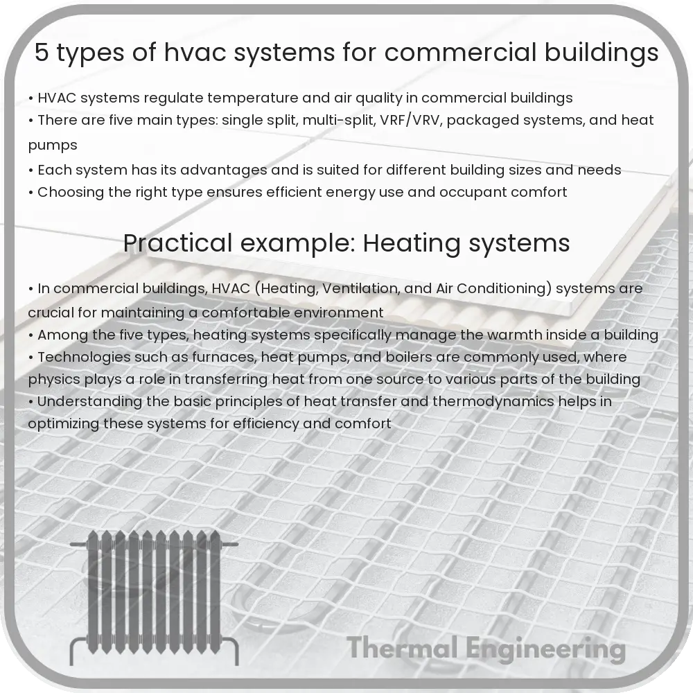
Heating, Ventilation, and Air Conditioning (HVAC) systems are crucial for maintaining a comfortable and safe environment in commercial buildings. They regulate indoor climate and ensure proper air quality, making them essential for spaces like offices, shopping centers, and other public and private facilities. There are several types of HVAC systems used in commercial settings, each with unique characteristics tailored to different needs and building sizes. Here’s a look at five common types:

1. Single Split Systems

Single split systems are among the most popular HVAC choices for smaller commercial buildings, such as small offices, shops, and cafes. These systems are affordable and easy to install. Each system serves a single room, which means you can manage the heating and cooling in individual spaces separately. This not only helps in controlling the environment according to each room’s specific requirements but also reduces energy wastage. A major advantage of single split systems is that even if one unit fails, the rest remain operational.

2. Multi Split Systems

Multi split systems work similarly to single split systems but can connect multiple indoor units to a single outdoor unit. This setup helps save on outdoor space and is beneficial for buildings with limited exterior areas that cannot accommodate multiple outdoor units. It uses inverter technology that allows compressors to adjust their speed based on the demand, which significantly improves energy efficiency. Multi split systems are suitable for medium-sized buildings with several rooms, such as larger offices or medical practices.

3. Variable Refrigerant Flow (VRF) or Variable Refrigerant Volume (VRV) Systems

Developed in Japan in the 1980s, VRF/VRV systems are targeted at buildings that need high levels of efficiency and the ability to control the environmental conditions in different parts of the building independently. These systems can provide both heating and cooling simultaneously to different areas, making them ideal for larger, multi-story buildings with varying temperature requirements across zones. They operate quietly and offer one of the best energy efficiencies on the market.

4. HVAC Chillers

Chiller systems provide cooling for buildings and industrial facilities. They remove heat from the indoor air through the use of chilled water, which circulates through a loop system. There are two types of chillers: air-cooled and water-cooled. Air-cooled chillers are usually installed outside and expel the heat absorbed from the indoor air directly into the outdoor air, while water-cooled chillers rely on a cooling tower to dispose of the absorbed heat. Chillers are particularly effective for high-rise buildings or large commercial spaces with significant cooling demands.

5. Rooftop Units

Rooftop units (RTUs) are large air-conditioning systems installed on the roof of buildings. They are common in commercial environments, notably in single-story buildings like warehouses or retail stores. RTUs are all-in-one systems that house all components — compressor, condenser, evaporator, and air handling unit — in a single cabinet. They can be customized with additional features like economizers, which use outside air to cool the building when the outside temperature is cooler than the indoor temperature, thus enhancing the system’s efficiency.

Choosing the right HVAC system for a commercial building depends on a variety of factors including the size of the building, the local climate, energy efficiency requirements, and budget constraints. Understanding the different types of systems available can help in making an informed decision that ensures comfort, efficiency, and cost-effectiveness.

12 Types of Wind Tunnels in Aerodynamic Testing

Learn about the 12 different types of wind tunnels and their unique applications in aerodynamic testing.

12 Types of Wind Tunnels in Aerodynamic Testing

Understanding the 12 Types of Wind Tunnels in Aerodynamic Testing

Wind tunnels are indispensable tools in the field of aerodynamics, used to simulate the actions of air on aircraft, vehicles, and other structures. They vary widely in terms of size, design, and function depending on the specific testing requirements. Here’s a look at 12 different types of wind tunnels and their distinct characteristics:

1. Low-Speed Wind Tunnels

These tunnels are designed for testing with air speeds below the speed of sound (Mach 1). They are commonly used in automotive testing, sports performance engineering, and basic aerodynamic research on aircraft.

2. High-Speed Wind Tunnels

High-speed wind tunnels operate at speeds ranging from just below to several times the speed of sound (Mach 1 to Mach 5). They are essential for testing supersonic and high-speed aircraft designs.

3. Subsonic Wind Tunnels

Subsonic wind tunnels are used for experiments where the airspeed is less than the speed of sound. They are useful for studying flow fields around objects, such as aircraft wings and automotive bodies, at realistic operating conditions.

4. Transonic Wind Tunnels

These facilities are used to study flow phenomena close to the speed of sound (around Mach 0.8 to Mach 1.2). Transonic tunnels are crucial for understanding the complex flow behaviors that occur when aircraft approach the speed of sound.

5. Supersonic Wind Tunnels

Designed to test airflows exceeding the speed of sound, these tunnels are key to advancing supersonic aircraft and missile technology. They generally operate in the range of Mach 1.2 to Mach 5.

6. Hypersonic Wind Tunnels

Hypersonic wind tunnels cater to testing at speeds greater than five times the speed of sound (Mach 5 and above). These are critical for research in spacecraft re-entry and advanced propulsion systems.

7. Continuous Flow Wind Tunnels

The air in these wind tunnels circulates continuously, providing a steady flow environment for extended testing periods. This type is ideal for endurance tests and detailed study of airflow characteristics.

8. Intermittent Wind Tunnels

These tunnels provide bursts of high-speed air for a short duration. They are particularly useful for initial testing phases where long-duration testing is not required.

9. Variable Density Wind Tunnels

Offering the ability to alter air density, these tunnels are vital for simulating high-altitude conditions. This capability makes them suitable for aerospace applications where density plays a crucial role in aerodynamic performance.

10. Cryogenic Wind Tunnels

In these wind tunnels, the testing environment is cooled to cryogenic temperatures, allowing for the simulation of extremely high altitudes and speeds. They are used primarily in aerospace research to study the effects of low temperatures on materials and aerodynamics.

11. Atmospheric Wind Tunnels

These facilities recreate the atmospheric conditions that objects might encounter in real-world applications. They are often used in the testing of building structures and vehicles to understand how they will perform in natural wind conditions.

12. Climatic Wind Tunnels

Climatic wind tunnels have the ability to control temperature, humidity, and other atmospheric conditions, in addition to wind speed. This type is indispensable for testing the performance of vehicles and components under various environmental conditions.

Each type of wind tunnel offers unique capabilities that are tailored to specific aerodynamic testing needs. From designing faster aircraft to ensuring the safety and efficiency of cars and buildings, wind tunnels play a pivotal role in engineering development across multiple industries.

9 Types of Air Conditioning Systems and Their Uses

Learn about different types of air conditioning systems, their functionalities, and how to choose the right one for your needs.

9 Types of Air Conditioning Systems and Their Uses

Introduction to Air Conditioning Systems

Air conditioning systems are essential in residential, commercial, and industrial settings, providing comfort and maintaining indoor air quality. There are several types of air conditioning systems available, each serving different purposes and suited to specific situations. Understanding the various systems can help in selecting the right one according to the needs, climate, and building characteristics.

1. Central Air Conditioning Systems

Central air conditioning systems are designed to cool large homes, offices, and buildings efficiently. These systems typically use a split system that includes an outdoor unit with a compressor and condenser and an indoor unit containing the evaporator coils and air handler. Ductwork is used to distribute cooled air throughout the building, returning it to the unit to be re-cooled.

2. Ductless Mini-Split Systems

Ductless mini-split systems are ideal for cooling rooms or specific areas in a home or building without the need for extensive ductwork. These systems consist of an outdoor compressor/condenser and one or more indoor air handling units. They are perfect for additions to houses, small apartments, or regions of a house that require independent temperature control.

3. Window Air Conditioners

Window air conditioners are compact units designed to cool a single room. They are installed in a window or through a wall and contain all components in one box. This type of AC is prevalent in small apartments or specific rooms within larger homes.

4. Portable Air Conditioners

Portable air conditioners are mobile, free-standing units that can be moved from room to room. They are typically vented through a window kit and are an excellent option for temporary space cooling or where window configurations do not allow for window units.

5. Hybrid/Dual Fuel Air Conditioners

Hybrid air conditioning systems combine a gas furnace with an electric air-source heat pump to provide a cost-effective and efficient heating and cooling solution. These systems automatically switch between burning fossil fuels and using electricity based on outside temperatures, optimizing energy use and reducing operating costs.

6. Geothermal Heating and Cooling Systems

Geothermal heating and cooling systems utilize the stable temperature of the earth a few feet below the surface to cool and heat the home. Pipes are installed in the ground through which a fluid circulates, absorbing or dissipating heat to the ground. These systems are highly efficient and environmentally friendly.

7. Packaged Terminal Air Conditioners (PTACs)

PTACs are self-contained units commonly found in hotels, hospitals, and apartment buildings. Each unit is installed through a wall and serves a single room with direct access to the outside. They provide both heating and cooling, allowing individual control with minimal installation.

8. Evaporative Coolers (Swamp Coolers)

Evaporative coolers, also known as swamp coolers, are suitable for hot, dry climates. They cool outdoor air by passing it over water-saturated pads, causing the water to evaporate and cool the air significantly. This cooled air is then circulated into the space. They are less energy-intensive than traditional air conditioning units but are limited to areas with low humidity.

9. Smart Air Conditioners

Smart air conditioners incorporate Wi-Fi and other technologies, allowing users to control them via smartphones or voice-activated home automation systems. These units provide convenience, improved energy management, and the ability to integrate with other smart home devices.

Conclusion

Choosing the right air conditioning system involves considering various factors, including the size of the area to be cooled, the local climate, energy efficiency, and costs. By understanding the different types of systems available, consumers can make informed choices that match their specific cooling needs and preferences.

6 Types of Steam Generators in Nuclear Plants

Explore the diverse types of steam generators used in nuclear power plants, including U-tube, OTSG, and integral models, crucial for efficient electricity production.

6 Types of Steam Generators in Nuclear Plants

Understanding the Types of Steam Generators in Nuclear Plants

Steam generators are a critical component in nuclear power plants, playing a pivotal role in the production of electricity. They are heat exchangers which convert water into steam using the heat produced from nuclear reactions. Depending on the design and type of reactor, different types of steam generators are used. Here, we explore six common types found in various nuclear power plants around the world.

1. U-Tube Steam Generator

One of the most prevalent types used in pressurized water reactors (PWRs) is the U-tube steam generator. In this design, water flows through a series of U-shaped tubes, which are surrounded by hot reactor coolant. This configuration allows the water in the tubes to absorb heat and convert into steam. The U-tube design helps in easy accommodation of thermal expansion and contraction, thus enhancing the safety and longevity of the equipment.

2. Once-Through Steam Generator (OTSG)

Used in some designs of boiling water reactors (BWRs) and in Canadian CANDU reactors, Once-Through Steam Generators operate with water flowing in one direction only, turning to steam as it absorbs heat from the nuclear core’s coolant. This type of steam generator operates without recirculation, differing from the U-tube where water circulates through a closed loop. OTSGs are simpler in design but require higher water quality to avoid deposits and clogging.

3. Recirculating Steam Generators

Mostly used in older designs of BWRs, recirculating steam generators use steam separators and dryers located at the top of the generator to recycle the steam-water mixture. The water is then returned to the lower part of the generator to be reheated and converted back into steam. This design generally improves thermal efficiency and steam quality.

4. Vertical Steam Generators

Typically seen in Russian VVER nuclear reactors, vertical steam generators are cylinder-shaped and stand upright. This design features a reduced height for the U-tubes, potentially leading to fewer tube vibrations and improved corrosion resistance under high temperatures.

5. Horizontal Steam Generators

Similar to the vertical type but oriented horizontally, horizontal steam generators are commonly found in Soviet-era RBMK reactors and some CANDU reactors. The horizontal orientation facilitates easier removal of sediments and dissolved gases, potentially lowering the risk of corrosion-related failures.

6. Integral Steam Generators

Integral steam generators are part of the newer generation of nuclear reactor designs like the Westinghouse AP1000 or the European Pressurized Reactor (EPR). Unlike the separate large steam generators in traditional designs, these are integrated into the reactor vessel itself. By incorporating the steam generation module inside the reactor vessel, the overall plant size and complexity are reduced, potentially increasing safety through fewer connections and joints.

Conclusion

Steam generators are central to the operation of nuclear power plants, providing the steam required to drive turbines and generate electricity. The type of steam generator used varies based on the reactor design, operational needs, and safety considerations. Understanding these types gives insights into how nuclear power plants efficiently and safely convert nuclear energy into electrical energy.

4 Types of Heat Pumps for Efficient Heating

Learn about heat pumps, efficient systems for heating and cooling using air, ground, or water sources, and their advantages and disadvantages.

4 Types of Heat Pumps for Efficient Heating

Introduction to Heat Pumps

Heat pumps are devices that transfer heat from one place to another to efficiently heat and cool buildings. By using a small amount of external power, they move thermal energy opposite to the direction of spontaneous heat flow. This makes them an environmentally friendly and cost-effective option for climate control. Commonly, heat pumps are categorized based on the source from which they extract heat. Let’s explore the four main types of heat pumps available in the market.

1. Air Source Heat Pumps (ASHPs)

Air Source Heat Pumps are among the most common types of heat pumps. These systems use the air outside your home as the heat source or sink. In the winter, they capture heat from the outdoor air and transfer it inside. Conversely, in the summer, they remove heat from the inside of your house to cool it. ASHPs are known for their ease of installation and lower initial cost compared to other types of heat pumps.

  • Advantages: Lower installation cost, effectiveness in moderate climates, and dual heating and cooling capabilities.
  • Disadvantages: Efficiency can decrease in extremely cold climates, and they can be less efficient than other types of heat pumps.

2. Ground Source Heat Pumps (GSHPs)

Ground Source Heat Pumps, also known as geothermal heat pumps, utilize the earth’s stable underground temperature to provide heating, cooling, and often, hot water. During the winter, heat is extracted from the ground through the loop and pumped into the indoor air. In summer, the process reverses, pulling heat from your home to deposit in the earth, which cools your home.

  • Advantages: Highly efficient, lower operating costs, environmentally friendly, quiet operation, and long lifespan.
  • Disadvantages: Higher initial installation cost, dependent on geological conditions, and requires significant land space or well drilling.

3. Water Source Heat Pumps (WSHPs)

Water Source Heat Pumps operate similarly to GSHPs but use water instead of soil as the heat exchange medium. These systems are particularly viable in properties located near bodies of water such as lakes, rivers, and ponds. The water’s temperature is more consistent than air temperature, providing efficient heating and cooling year-round.

  • Advantages: Good efficiency, works well in a variety of climates, and can be more efficient than air source heat pumps.
  • Disadvantages: Installation can be challenging and costly, dependent on proximity to water sources, and may have environmental regulations.

4. Hybrid Heat Pumps

Hybrid Heat Pumps combine the features of air source heat pumps with another heating technology like gas, oil, or electric furnaces. This allows them to optimize energy usage and operating costs according to the outside temperature and energy prices. When conditions are mild, the ASHP operates; when it gets too cold for the ASHP to operate efficiently, the secondary heating system kicks in.

  • Advantages: Optimizes energy use, maintains efficiency in extreme weather, and reduces dependency on non-renewable resources.
  • Disadvantages: Higher initial costs due to dual systems, complex installation, and maintenance.

Conclusion

Heat pumps are a versatile and sustainable option for heating and cooling homes and buildings. Whether you choose an air, ground, water source, or hybrid system depends on your geographical location, climate, budget, and environmental goals. Considering the efficiency and long-term savings they offer, heat pumps represent a significant step forward in residential and commercial heating technology.

Heat transfer in osmotic power generation

Explore the impact of heat transfer on the efficiency and stability of osmotic power generation systems, focusing on conduction, convection, and radiation effects.

Heat transfer in osmotic power generation

Understanding Heat Transfer in Osmotic Power Generation

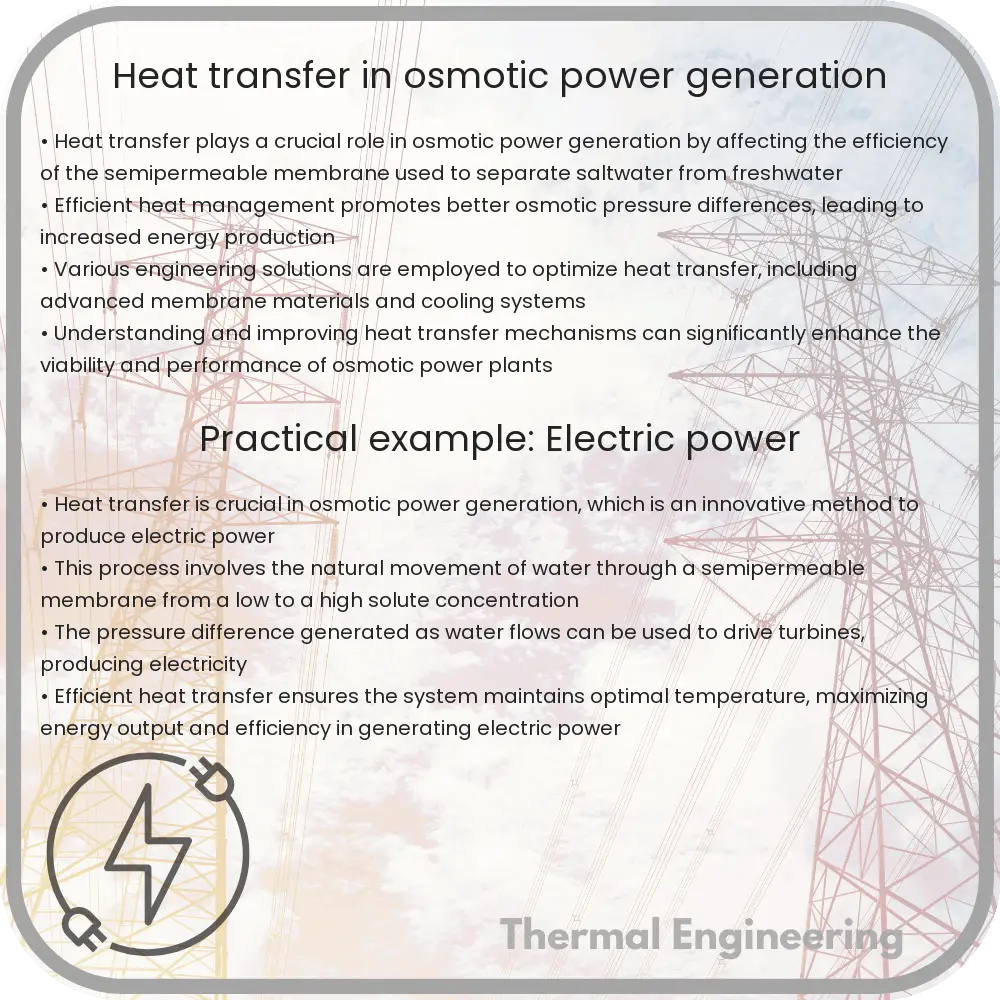
Osmotic power generation, also known as salinity gradient power, exploits the energy available from the difference in the salt concentration between seawater and river water. A key component of understanding and optimizing osmotic power systems is the analysis of heat transfer processes involved. This article will explore how heat transfer affects osmotic power generation systems and the principles behind managing these thermal effects.

Basics of Osmotic Power Generation

Osmotic power generation utilizes a semi-permeable membrane that separates two fluids with different salinity levels—typically seawater and freshwater. The natural process of osmosis causes water to move from the less concentrated solution to the more concentrated saline solution, creating pressure on the seawater side. This pressure can be harnessed to drive turbines and generate electrical power.

Role of Heat Transfer

Heat transfer in osmotic power plants can affect both the efficiency and stability of power generation. There are three types of heat transfer mechanisms to consider:

  • Conduction: Thermal energy is transferred through materials by molecular interaction. In osmotic power systems, heat conduction occurs through the membrane and the boundary layers of fluids in contact with the membrane.
  • Convection: Heat is carried along by the movement of the fluid. This occurs when warm water mixes with cooler water, potentially affecting the osmotic pressure differential across the membrane.
  • Radiation: Thermal energy emitted in the form of electromagnetic waves. Although less significant in osmotic power systems, it can contribute to the overall heat balance.

Thermal Effects on Membrane Performance

The performance of the semi-permanent membrane is crucial to the effectiveness of osmotic power generation. Temperature changes can influence membrane permeability and selectivity, impacting the efficiency of power generation. Higher temperatures typically increase the permeability of the membrane, which can enhance water flux but might also lead to increased passage of salt ions, reducing the osmotic pressure difference.

Managing Heat Transfer

Effective management of heat transfer is essential for optimizing osmotic power generation. Engineers use several strategies to control the thermal environment within osmotic power plants:

  1. Thermal Insulation: Reducing unwanted heat exchange with the environment through the use of insulating materials around pipes and membranes.
  2. Temperature Regulation: Maintaining an optimal range of operating temperatures to maximize membrane performance and minimize thermal degradation.
  3. Heat Exchangers: Employing heat exchangers can counteract the undesirable temperature changes caused by the mixing of fluids with different temperatures.

Conclusion

Heat transfer plays a significant role in the efficiency and operational capacity of osmotic power generation systems. By understanding and controlling thermal interactions, engineers can enhance the performance and durability of these innovative renewable energy systems. With ongoing research and development, the management of heat transfer in osmotic power is poised to become even more sophisticated, promising a cleaner and more sustainable energy future.

3 Types of Thermodynamic Cycles and Their Applications

Learn about thermodynamic cycles, essential processes in engineering systems like engines and refrigerators, exploring types like Carnot, Rankine, and Brayton cycles.

3 Types of Thermodynamic Cycles and Their Applications

Understanding Thermodynamic Cycles

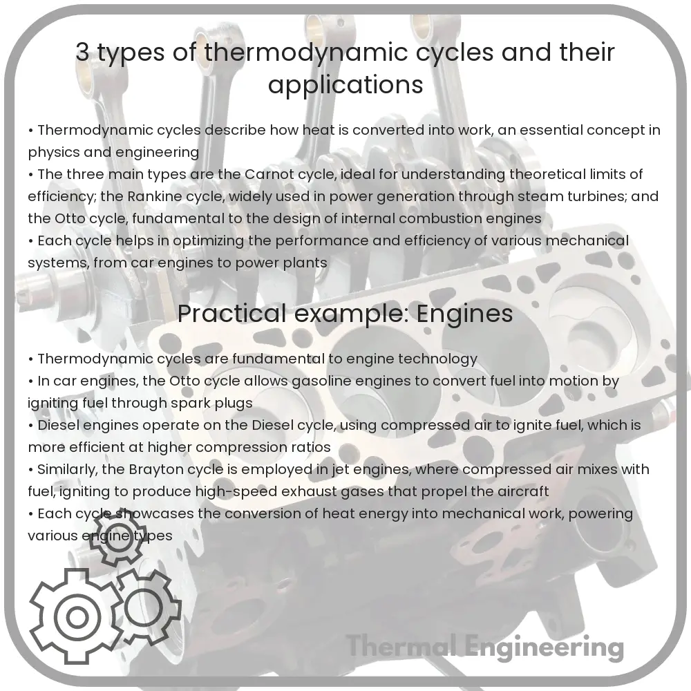
Thermodynamic cycles are processes that involve heat and work transferring in and out of systems, typically interpreted through a series of thermodynamic processes that return a system to its initial state. These cycles are fundamental to the operation of many engineering systems, including engines and refrigerators. In this article, we will explore three significant types of thermodynamic cycles and their applications in real-world devices.

Carnot Cycle

The Carnot cycle is a theoretical thermodynamic cycle proposed by Nicolas Léonard Sadi Carnot. It is considered the most efficient cycle for converting a given amount of thermal energy into work or vice-versa. The cycle has four reversible processes: two isothermal (constant temperature) and two adiabatic (no heat exchange).

  • Isothermal Expansion: The system (usually a gas) expands at constant temperature by absorbing heat from a high-temperature reservoir.
  • Adiabatic Expansion: The system expands without any heat exchange, which drops its temperature and pressure.
  • Isothermal Compression: The system is compressed at a lower constant temperature, releasing heat to a low-temperature reservoir.
  • Adiabatic Compression: Compression occurs without heat exchange, increasing the system’s temperature and pressure back to its original state.

The Carnot cycle is used primarily as an ideal standard against which the actual performance of heat engines can be compared. Its efficiency, given by \( \eta = 1 – \frac{T_{\text{cold}}}{T_{\text{hot}}} \) where \( T_{\text{cold}} \) and \( T_{\text{hot}} \) are the temperatures of the cold and hot reservoirs, respectively, signifies the maximum possible efficiency that any heat engine can achieve operating between these two reservoirs.

Rankine Cycle

The Rankine cycle is used extensively in power generation, especially in steam-powered engines found in thermal power plants. It mirrors many steps of the Carnot cycle but uses a pump and steam turbine for the working of the cycle.

  • Pumping: Liquid water is pumped from a low to a high pressure, raising its temperature.
  • Boiling and Superheating: At high pressure, the water is heated in a boiler, turning it into steam and then superheated beyond its boiling point.
  • Expansion through Turbine: The superheated steam expands through a turbine, producing work by rotating the turbine’s blades.
  • Condensation: The steam leaves the turbine, enters a condenser, and is condensed back into liquid water by releasing its heat to the surrounding environment.

The work done by the turbine generates most of the electrical power while the pump consumes a part of this work, reflecting an overall conversion of heat to work. The efficiency improvements in the Rankine cycle have been primarily focused on increasing the temperature and pressure limits of the steam.

Brayton Cycle

The Brayton cycle (or Joule cycle) depicts the workings of a gas turbine engine, which is commonly used in aircraft engines and power plants. It consists of three main processes:

  • Compression: Air is compressed in a compressor, increasing pressure and temperature.
  • Combustion: Fuel is injected and combusted at constant pressure, greatly increasing the temperature and expanding the air.
  • Expansion: The high-temperature, high-pressure air expands through a turbine, creating work that propels the compressor and may drive an additional output such as an electrical generator.

This cycle is known for its ability to produce a high power output at high efficiencies and is favored in settings where size and responsiveness are critical.

The applications of these thermodynamic cycles range from small home appliances like refrigerators and air conditioners to major power generation systems dominating the industrial landscape. Understanding these cycles enables engineers and scientists to innovate and improve upon existing technologies, making energy usage more efficient and sustainable.

7 Types of Pipe Flow in Fluid Engineering

Learn about the seven main types of pipe flow in fluid engineering, crucial for system design in various industries.

7 Types of Pipe Flow in Fluid Engineering

Understanding the 7 Types of Pipe Flow in Fluid Engineering

In fluid engineering, understanding how fluids flow through pipes is crucial for designing efficient systems in various applications, including water supply, oil and gas transport, and chemical processing. Flow can be classified into different types depending on several factors such as the fluid’s speed, its viscosity, the pipe’s diameter, and the overall pressure of the system. Here, we explore the seven main types of pipe flow which are essential for engineers and designers.

1. Laminar Flow

Laminar flow, or streamline flow, occurs when a fluid flows in parallel layers with no disruption between the layers. This type of flow is characterized by smooth paths of the particles of the fluid, occurring typically at lower velocities. The condition for laminar flow can be defined using the Reynolds number (Re), calculated by \( \text{Re} = \frac{\rho \cdot v \cdot D}{\mu} \) where ρ is the fluid density, v is the flow velocity, D is the diameter of the pipe, and μ is the dynamic viscosity of the fluid. Laminar flow is observed when Re < 2,000.

2. Turbulent Flow

Turbulent flow is characterized by chaotic and erratic changes in pressure and velocity within the fluid. Unlike laminar flow, the fluid particles undergo irregular fluctuations and mixing. Turbulence typically occurs at high velocities and large pipes, with a Reynolds number greater than 4,000.

3. Transitional Flow

This flow type is a mix between laminar and turbulent flow. In transitional flow, both laminar flow at the core and bursts of turbulence occur intermittently. This transition typically happens when the Reynolds number is between about 2,000 and 4,000.

4. Compressible Flow

Compressible flow occurs when the density of the fluid changes significantly along with the flow. This typically happens when fluids are moving at high speeds, close to or exceeding the speed of sound. Such conditions are relevant in high-speed jet engines and aerodynamics.

5. Incompressible Flow

Incompressible flow describes fluid movement where its density is constant. Most liquids (like water and oil) can be treated as incompressible fluids under ordinary conditions. Incompressible flow assumptions simplify the analysis and calculations in many engineering applications.

6. Steady Flow

A steady flow occurs when the velocity of the fluid at a particular point does not change over time. Whether the flow is laminar or turbulent, if the conditions remain constant, it is considered steady. This is an ideal scenario often used in engineering calculations.

7. Unsteady Flow

Opposite to steady flow, unsteady (or transient) flow happens when the fluid’s velocity at a point changes as time progresses. Situations causing unsteady flow include changes in the fluid velocity, fluid source (pump operation changes), or system configurations (valve manoeuvring).

Understanding these types of flow helps in the computational fluid dynamics (CFD) modeling, design, and optimization of systems involving fluid transport. By choosing the appropriate flow model, engineers can predict how fluids will behave in real-world scenarios, ensuring safety, efficiency, and operational success.