Facebook Instagram Youtube Twitter

8 Types of Viscosity in Fluids Explained

Learn about the various types of viscosity measurements crucial for understanding fluid behavior in engineering and science.
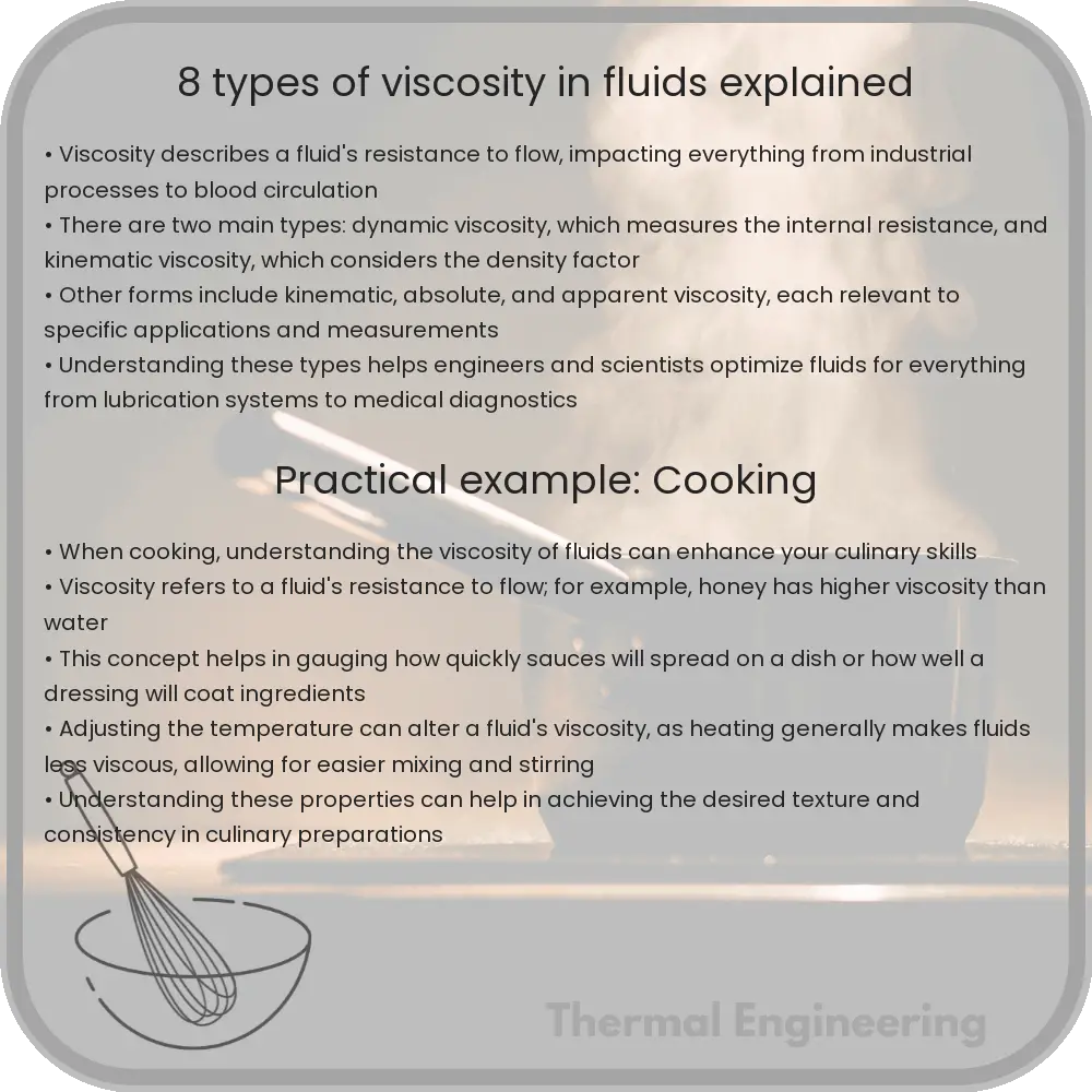
8 Types of Viscosity in Fluids Explained

Understanding the Types of Viscosity in Fluids

Viscosity is a fundamental property of fluids which describes their internal resistance to flow. In simple terms, it’s a measure of how “thick” or sticky a fluid is. Viscosity is a crucial factor in areas such as engineering, meteorology, and even in everyday products like oils and paints. There are several ways to classify and understand viscosity, and here we will explore eight types of viscosity measurements and concepts important in fluid dynamics and various applications.

Different Types of Viscosity

1. Dynamic (Absolute) Viscosity

The dynamic viscosity of a fluid is a measure of its resistance to gradual deformation by shear stress or tensile stress. For liquids, it corresponds to the informal notion of “thickness. For example, honey has a higher dynamic viscosity than water. It’s typically measured in pascal-seconds (Pa·s) in the International System of Units (SI).

2. Kinematic Viscosity

Kinematic viscosity is the ratio of dynamic viscosity to fluid density. It describes the fluid’s internal resistance to flow under gravity. Kinematic viscosity is often used in the study of fluid dynamics and is measured in units of m²/s. It’s particularly useful when analyzing the Reynolds number, which helps predict flow patterns in different fluid flow situations.

3. Absolute Viscosity

Absolute viscosity (another term for dynamic viscosity) refers to the force required to move one layer of fluid in relation to another layer. The common unit used to express absolute viscosity is the poise (P), which is more traditional but still widely used in various fields, including engineering.

4. Apparent Viscosity

Apparent viscosity is used in non-Newtonian fluids where viscosity changes with the rate of shear strain. This type of viscosity is calculated at a specific shear rate and can vary depending on conditions, such as in fluids like ketchup or whipped cream, which behave differently under stress.

5. Rotational Viscosity

Rotational viscosity is measured using rotational viscometers where the fluid is sheared within a cylindrical or cup-like apparatus. This method can be useful for characterizing viscosity in paints, coatings, and other materials that are affected by rotational forces.

6. Shear Viscosity

Shear viscosity refers to the viscosity measured when the fluid is subjected to shear flow, caused due to parallel plates moving at different velocities. This measurement is crucial in engineering applications such as lubrication and aerodynamics.

7. Extensional Viscosity

Extensional viscosity is a measure of a fluid’s resistance to lengthening in an extensional flow. Unlike shear flow, extensional flows involve changes in fluid body shape without any rotation. It’s particularly informative in processes like fiber spinning, jet fuel injection, and inkjet printing.

8. Viscosity Index

The Viscosity Index (VI) is an empirical dimensionless number that indicates how much a fluid’s viscosity changes with temperature. A higher VI means the viscosity changes less with temperature variations, which is important for motor oils and hydraulic fluids that must perform across a range of temperatures.

Conclusion

Viscosity is a versatile and vital concept in both natural and industrial processes. Understanding the different types of viscosity helps engineers, scientists, and even everyday consumers make informed decisions about materials and fluids in their specific contexts. By applying these concepts, one can better understand how fluids will behave under different conditions, leading to more efficient and effective designs and applications.
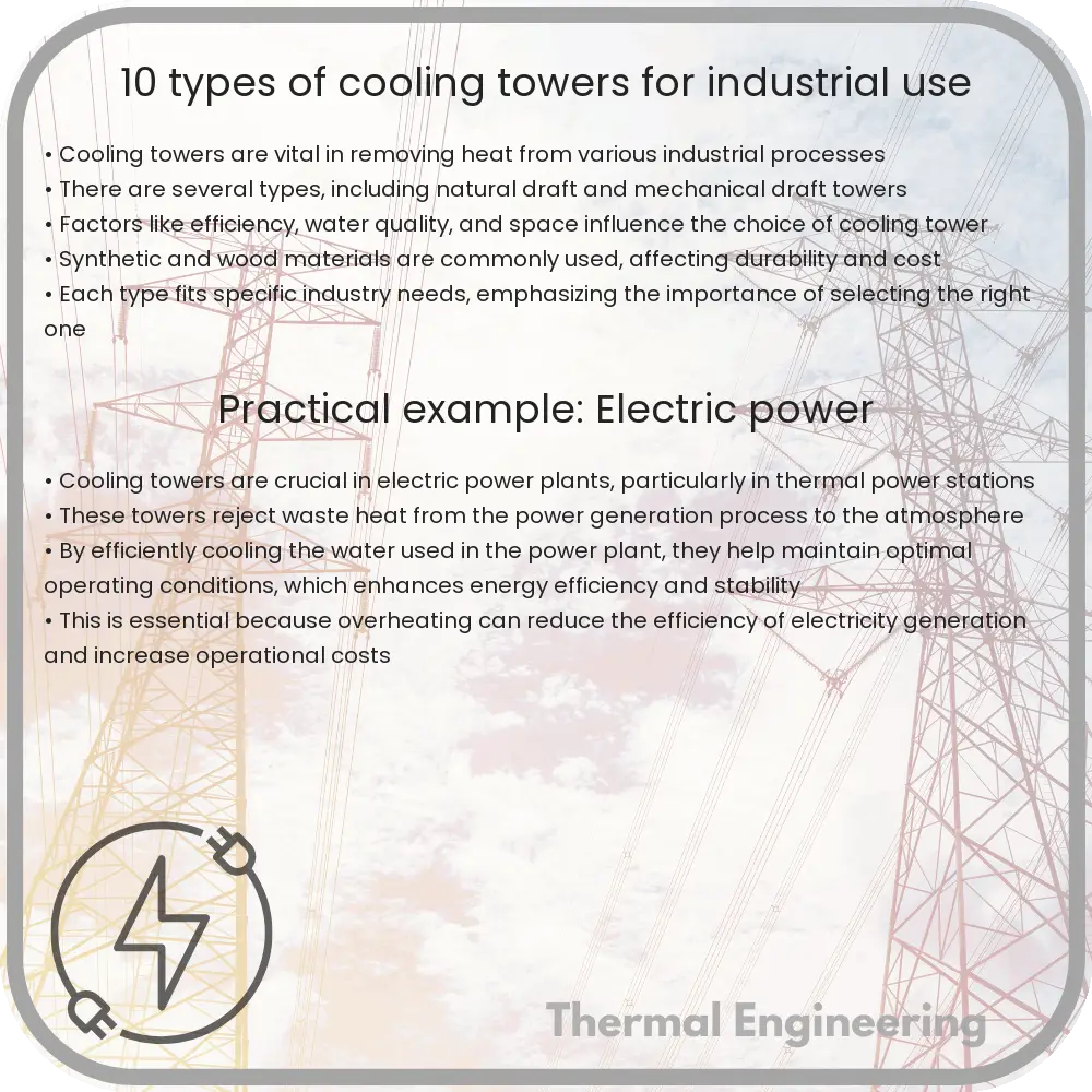
10 Types of Cooling Towers for Industrial Use

Learn about the functions, types, and selection criteria of cooling towers in industrial settings.

10 Types of Cooling Towers for Industrial Use

Introduction to Cooling Towers

Cooling towers are a critical component in many industrial processes where heat needs to be dissipated to keep systems operational. These structures are used to remove excess heat from a cooling system by lowering the temperature of the water processed in the plant. This is typically achieved through the evaporation of water to remove process heat and cool the working fluid to near the wet-bulb air temperature. Cooling towers can vary widely in size, design, and functionality depending on the needs of the process and the climatic conditions.

Types of Cooling Towers

There are several types of cooling towers used in industrial settings, each with unique features and specific applications. Here’s a roundup of 10 common types:

  1. Natural Draft Cooling Towers

    Utilize the natural upward flow of air to cool the water. They are typically very large, often used in power plants and other facilities with high cooling demands. Their operation is largely dependent on the ambient weather conditions.

  2. Mechanical Draft Cooling Towers

    These towers use fans to force or draw air through circulated water. They are divided into further categories:

    • Forced Draft: Air is forced through the tower by fans located at the air inlet.
    • Induced Draft: Air is drawn through the cooling tower by fans located at the discharge (exiting airflow).
  3. Crossflow Cooling Towers

    In these towers, the air flows horizontally through the falling water. This design allows for easy maintenance and reduced water clogging.

  4. Counterflow Cooling Towers

    Air flows vertically upward, counter to the flow of falling water within the tower. This design typically provides better heat removal efficiency than crossflow towers.

  5. Hyperbolic Cooling Towers

    These towers feature a distinctive hyperbolic structure that facilitates the natural flow of air, enhancing cooling efficiency through efficient circulation patterns. They are often used in large power plants.

  6. Field Erected Cooling Towers

    Designed and constructed on the site, these are typically large structures that cater to industrial plants needing high-capacity cooling. They can be built in both crossflow and counterflow configurations.

  7. Package Cooling Towers

    Preassembled and relatively smaller than field erected types, these are used in smaller applications like light industrial and commercial processes. They are easy to install and maintain.

  8. Plume Abated Cooling Towers

    Designed to minimize the visible steam plume typically associated with conventional cooling towers. They are used in environments where the plume needs to be controlled to reduce visual impact or to comply with regulatory standards.

  9. Fluid Coolers or Closed Circuit Cooling Towers

    These operate with a closed-loop system, meaning the process fluid is cooled without direct contact with the air or water. These towers avoid contamination and are generally used when the circulated fluid cannot be exposed to the open air.

  10. Evaporative Condensers

    Designed to condense a refrigerant gas and cool it using water and a fan system. These are especially useful in refrigeration and HVAC systems.

Choosing the Right Cooling Tower

The choice of a cooling tower depends on several factors including the cooling load requirements, environmental conditions, water quality, space availability, and energy consumption. Additionally, each type of cooling tower has its own set of maintenance needs, cost implications, and operational efficiencies. Understanding the specific requirements of your industrial process can greatly aid in selecting the most appropriate cooling tower type.

Conclusion

Cooling towers are essential for managing heat in industrial environments. From massive hyperbolic towers to compact packaged models, the range of cooling tower types available today can meet virtually any industrial cooling need. Selecting the right type not only ensures efficient cooling but also optimizes operational costs and sustainability efforts.

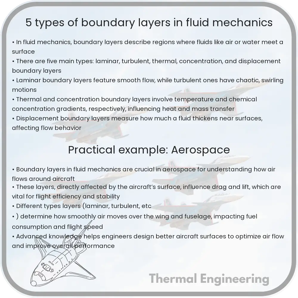
5 Types of Boundary Layers in Fluid Mechanics

Learn about boundary layers in fluid mechanics, fundamental to understanding fluid flow phenomena in various engineering contexts.

5 Types of Boundary Layers in Fluid Mechanics

Introduction to Boundary Layers in Fluid Mechanics

In the study of fluid mechanics, the boundary layer is a fundamental concept describing the layer of fluid in the immediate vicinity of a bounding surface where effects of viscosity are significant. Here, we explore five types of boundary layers that are crucial in understanding different fluid flow phenomena around objects in engineering applications such as in aerodynamics, hydrodynamics, and within various fluid machinery.

1. Laminar Boundary Layer

A laminar boundary layer is characterized by the smooth, orderly flow of fluid particles where viscous forces are dominant. In this layer, fluid moves in parallel layers with no disruption between them. This type of flow typically occurs at lower Reynolds numbers (Re) and is significant in applications involving precision and minimal drag, such as in microfluidics. The transition from laminar to turbulent flow depends on factors like surface roughness, flow velocity, and fluid characteristics.

2. Turbulent Boundary Layer

Unlike the laminar layer, a turbulent boundary layer involves chaotic fluid motion where inertial forces overpower viscous forces, leading to mixing. Turbulent flows increase thermal exchange efficiency and momentum but also contribute to higher energy loss due to friction. They typically occur at high Re and are common in many industrial processes and natural phenomena, such as weather systems and ocean currents.

3. Thermal Boundary Layer

The thermal boundary layer forms when a temperature gradient exists between the fluid and a surface. In this region, heat transfer takes place between the fluid and the interface, affecting the fluid’s temperature and density. The thickness of this layer varies with the thermal conductivity of the fluid and influences the overall heat transfer rate in processes like cooling of electronic devices or heating in boilers.

4. Blasius Boundary Layer

The Blasius boundary layer describes the steady two-dimensional laminar flow of an incompressible fluid over a flat plate, which is aligned at a zero angle to the flow. Developed by Paul Richard Heinrich Blasius, it’s governed by the Blasius equation, a third-order nonlinear ordinary differential equation, given by:

\( \frac{d^3f}{d\eta^3} + \frac{1}{2}f \frac{d^2f}{d\eta^2} = 0 \)

This equation helps predict the boundary layer thickness and velocity profile along the plate.

5. Von Kármán Boundary Layer

The Von Kármán boundary layer deals with the flow of viscous fluid past a spinning object. Named after Theodore von Kármán, this type of boundary layer captures the effects of rotation which introduces centrifugal and Coriolis forces, complicating the flow dynamics. It’s particularly crucial in the design and analysis of turbines and swirled flow equipment.

Conclusion

Understanding these different types of boundary layers forms a cornerstone in fluid dynamics studies, impacting the design, operation, and analysis of many engineering systems. Each type presents unique challenges and opportunities, making the exploration of fluid behaviors near surfaces both complex and fascinating.

4 Types of Convection Heat Transfer Techniques

Learn about convection heat transfer techniques, including natural and forced convection, and internal and external flow applications.

4 Types of Convection Heat Transfer Techniques

Understanding Convection Heat Transfer: 4 Key Techniques

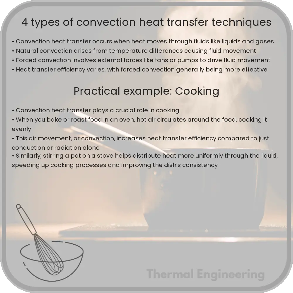
Convection heat transfer is a fundamental concept in both engineering and physics, playing a critical role in a wide range of applications from industrial processes to everyday appliances like heating systems and air conditioners. Convection involves the transfer of heat by the physical movement of a fluid (which can be a liquid or a gas) over a surface. The efficiency of convection can be significantly enhanced or controlled using different techniques. Here, we explore four main types of convection heat transfer techniques: natural convection, forced convection, internal flow, and external flow.

Natural Convection

Natural convection occurs when the flow of the fluid is caused by density differences that arise from temperature variations within the fluid. No external force (like a pump or a fan) is needed. This type of convection is commonly seen around radiators, hot beverages cooling at room temperature, or in the heating of a room by a single heat source.

  • Buoyancy: The driving force behind natural convection is buoyancy, where warmer, less dense fluid rises and cooler, denser fluid descends.
  • Application: Natural convection is used in designing passive cooling systems, for example, in buildings and solar panels.

Forced Convection

Forced convection involves moving a fluid by external means such as a fan, pump, or suction device over a surface. The increased control over fluid movement generally enhances the heat transfer rate compared to natural convection.

  • Implementation: Common applications include automotive cooling systems where fans propel air over radiator surfaces, and HVAC systems in buildings.
  • Control: With forced convection, engineers can specifically tailor flow systems to maximize efficiency, such as adjusting the speed of fans or pumps.

Internal Flow

In internal flow convection, fluid moves through a confined space such as pipes or ducts. The heat transfer occurs between the fluid and the surface of these boundaries.

  • Characteristics: A significant aspect is the development of a boundary layer where the fluid velocity changes from zero at the wall (due to the no-slip condition) to a maximum value away from the wall.
  • Examples: Heating systems in buildings often use hot water flowing through pipes, and numerous industrial processes rely on heat transfer in tubes for fluids and gases.

External Flow

External flow pertains to the convection where fluids flow over objects as opposed to within them. Here, the object being cooled or heated is directly exposed to the fluid.

  • Dynamics: The flow of the fluid creates different layers and patterns around the surfaces it encounters, which can be critical in optimizing heat transfer.
  • Utilizations: Applications are varied, including the cooling of electronic devices through air flow or the heating of vehicle surfaces to de-ice in colder climates.

In conclusion, heat convection is a versatile mechanism used in numerous engineering and technical applications. Understanding the distinctions between natural and forced convection, and internal and external flows, allows engineers to design more efficient and effective heating and cooling systems. Each technique offers unique advantages and is chosen based on the specific requirements of the application, allowing for significant improvements in thermal management and energy conservation.

7 Types of Aerodynamics Flow Patterns

Learn about the seven fundamental types of aerodynamic flow patterns crucial for optimizing vehicle and system design.

7 Types of Aerodynamics Flow Patterns

Understanding the 7 Types of Aerodynamic Flow Patterns

Aerodynamics is a branch of dynamics concerned with studying the motion of air and how it interacts with objects in motion. Engineers and scientists study aerodynamic flows to design more efficient airplanes, cars, trains, and other systems. There are several types of aerodynamic flow patterns, each with distinct characteristics and implications. Here, we will explore seven fundamental types.

Laminar Flow

Laminar flow occurs when air moves smoothly and in parallel layers, with little to no mixing between them. This type of flow is characterized by its orderly motion and occurs generally at lower speeds and with smaller, streamlined bodies. The mathematical representation of laminar flow typically involves simple, linear equations. Laminar flow is crucial in applications where minimal drag and turbulence are desired.

Turbulent Flow

Unlike laminar flow, turbulent flow is characterized by chaotic changes in pressure and flow velocity. It involves eddies, swirls, and other disturbances, which are more efficient at mixing the flow. Turbulent flow is common in many natural and industrial scenarios, particularly at high velocities and with complex shapes. Although difficult to model mathematically due to its chaotic nature, understanding turbulent flow is essential for aerodynamic efficiency and stability.

Subsonic Flow

Subsonic flows are those where the flow velocity is less than the speed of sound. Most aerodynamic studies deal with subsonic flow because it’s the most common scenario for commercial and general aviation. In subsonic aerodynamics, the air behaves incompressibly for the most part, meaning that its density remains constant despite variations in flow speed.

Supersonic Flow

Supersonic flow occurs when the velocity of the flow exceeds the speed of sound. This type of flow introduces shock waves, which are characterized as sudden changes in pressure and flow velocity. The study of supersonic flow is crucial in the design of faster-than-sound transports, like supersonic jets and certain aerospace applications.

Transonic Flow

Transonic flow covers the speed range around the speed of sound, typically recognized as Mach numbers from 0.8 to 1.2. Transonic flows are complex because they feature a mix of subsonic and supersonic flow characteristics. Airplanes passing through this flow regime experience both kinds of phenomena, making stability and control challenging.

Compressible Flow

When dealing with high speeds, especially near or above the speed of sound, the density of air can change significantly in response to pressure changes. This scenario is called compressible flow. Compressible flow equations are essential for describing the behavior of gases in these conditions and are fundamental in supersonic and hypersonic aerodynamics.

Steady and Unsteady Flow

Steady flow refers to the scenario where fluid properties at a point do not change over time. In contrast, unsteady flow describes situations where the velocity and pressure fluctuate over time. The distinction between steady and unsteady flows is crucial in the analysis of various engineering problems, from the flutter of airplane wings to the pulsating flow in engines.

Each of these flow patterns has specific characteristics and complexities, making the field of aerodynamics both rich and challenging. By understanding these fundamental flow types, engineers can better design and optimize vehicles and systems to operate efficiently under various conditions.

6 Types of Thermal Power Stations and Their Features

Learn about thermal power stations, facilities that convert heat to electrical energy, including types like coal, gas, and biomass plants.

6 Types of Thermal Power Stations and Their Features

Introduction to Thermal Power Stations

Thermal power stations are facilities that convert heat energy into electrical energy. This process involves burning fuel to produce heat, which is then used to convert water into steam. The high-pressure steam spins the turbines connected to a generator, producing electricity. The choice of fuel and technology varies, leading to different types of thermal power stations. Here are six common types and their features.

1. Coal-Fired Power Plants

Coal-fired power plants are one of the most traditional types of thermal power stations. They operate by burning coal to produce steam that drives large turbines. These plants are known for their capacity to generate a significant amount of electricity, catering to large-scale energy demands. However, they face criticism for their environmental impact, primarily due to high carbon dioxide emissions and other pollutants such as sulfur dioxide and nitrogen oxides.

2. Oil-Fired Power Plants

Similar to coal-fired plants, oil-fired power plants burn oil to generate steam. These plants typically come into play in regions where coal supplies are not readily available but where oil can be easily imported. While they are more expensive to operate due to the high cost of oil, they can be activated quickly to meet peak electricity demands. Oil power plants also contribute to high emissions of greenhouse gases and particulate matter.

3. Natural Gas-Fired Power Plants

Natural gas power plants burn natural gas to produce electricity. They are favored for their efficiency and quick ramp-up times, making them ideal for meeting sudden increases in energy demand. Compared to coal and oil, natural gas burns cleaner, resulting in lower emissions of carbon dioxide and nearly negligible amounts of sulfur dioxide and particulates. These features make natural gas plants a popular choice in modern power generation systems.

4. Combined Cycle Power Plants

Combined cycle power plants represent a significant advancement in thermal power technology. These plants utilize both gas and steam turbines to achieve higher efficiency. Natural gas is burned in a gas turbine, and the waste heat from the gas turbine is used to produce steam for a steam turbine. This arrangement can achieve efficiencies of up to 60%, which is considerably higher than traditional fossil-fuel plants. The dual utilization of gas and steam phases reduces fuel consumption and emissions.

5. Cogeneration (CHP) Plants

Cogeneration, or combined heat and power (CHP), plants optimize the energy output from fuel burning by producing both electricity and usable heat. These systems are often employed in industrial settings or large institutions such as hospitals and universities, where concurrent demand for heat (or steam) and electricity exists. Cogeneration significantly enhances energy efficiency, as it can convert up to 90% of fuel energy into useful outputs, drastically reducing energy wastage and emissions.

6. Biomass Power Plants

Biomass power plants use organic materials for fuel, such as crop waste, wood chips, and other plant-based material. These resources are renewable, making biomass plants a more sustainable option than fossil fuel-based power stations. The combustion of biomass releases energy that is used to produce steam, driving turbines to generate electricity. While they help in reducing dependence on fossil fuels, challenges include the management of fuel supply and relatively lower energy efficiency compared to gas or combined cycle plants.

Conclusion

Each type of thermal power station has unique features and applications, influenced by factors such as fuel availability, cost, efficiency, and environmental impacts. Understanding these differences is crucial for making informed decisions regarding energy production and policy-making aimed at sustainable development. As technology and environmental policies evolve, the landscape of thermal power generation is also expected to undergo significant changes.

9 Types of Pumps in Fluid Mechanics

Learn about the various types of pumps used in fluid mechanics, including centrifugal, diaphragm, and positive displacement pumps, each suited for specific industrial applications.

9 Types of Pumps in Fluid Mechanics

Introduction to Types of Pumps in Fluid Mechanics

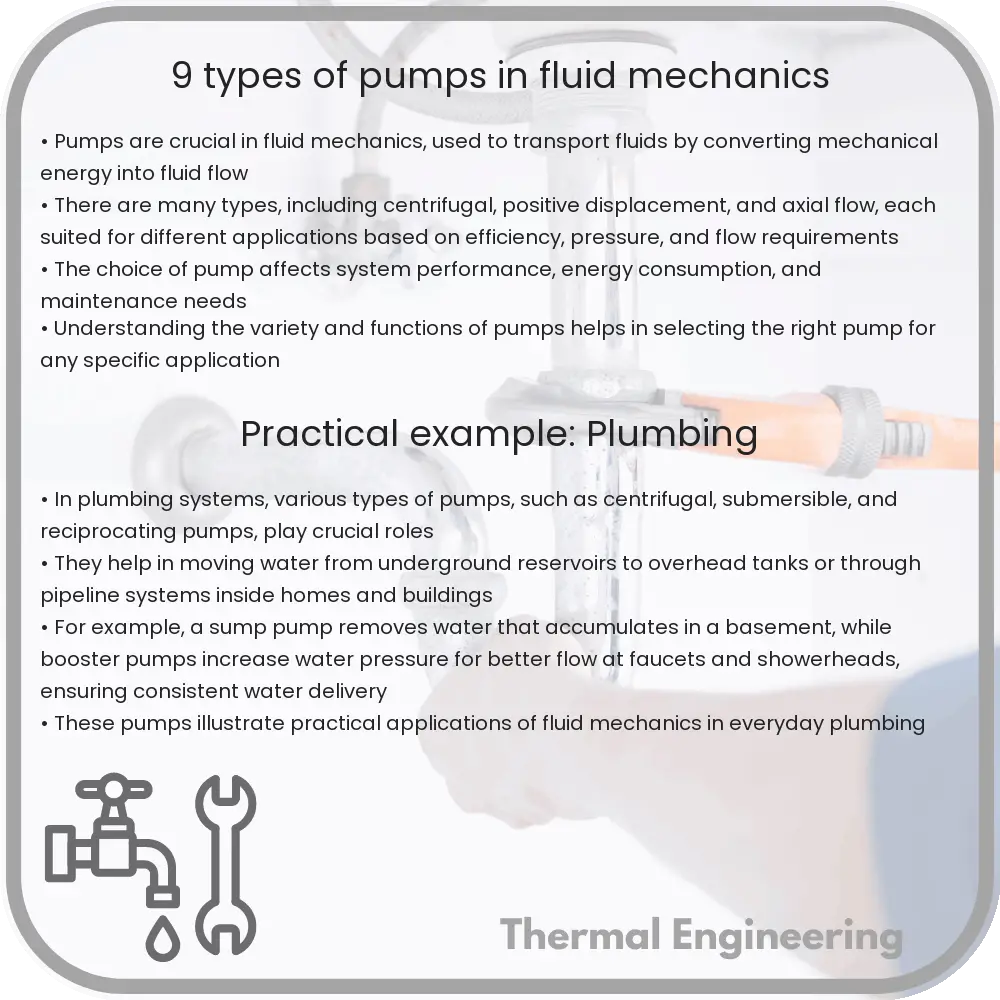
Pumps are essential devices in fluid mechanics, used primarily to transport liquids from one location to another. They play crucial roles in various industries such as water treatment, oil and gas, chemical processing, and more. Pumps are categorized based on their operational mechanisms and the applications they suit. Understanding these classifications helps in choosing the right pump for the right job.

Centrifugal Pumps

This is the most common type of pump, characterized by the use of a rotating impeller to accelerate fluid outward from the center of rotation. The fluid gains both speed and pressure as it moves through the impeller. Centrifugal pumps are typically used for large discharge throughputs and where the fluid pumping does not contain air or vapors.

Positive Displacement Pumps

Positive displacement pumps move a fixed amount of fluid with each operation cycle. They provide a steady and consistent flow regardless of the system pressure, making them ideal for applications requiring precise volume management. This category includes gear pumps, screw pumps, and piston pumps, each using a different mechanism to trap the fixed volume and force it into the discharge pipe.

Diaphragm Pumps

Also classed as a type of positive displacement pump, diaphragm pumps use a flexible membrane that reciprocates back and forth, creating a variable-volume chamber on one side of the membrane and controlling fluid movement. They are particularly useful for handling hazardous, toxic, or corrosive fluids, as the fluid does not come into contact with moving parts.

Submersible Pumps

These pumps are completely submerged in the fluid they are pumping. They are commonly used for pumping water from wells, removing bilge water from ships, and in other applications where the pump can be completely immersed. Submersible pumps are efficient in deep water installations, avoiding the need for complex suction mechanisms.

Jet Pumps

Jet pumps employ high velocity to capture fluid and transport it. They often mix the drive fluid with the fluid being pumped, which increases the velocity of the fluid mixture. Jet pumps are particularly effective in applications involving the extraction of liquids from considerable depths, such as wells.

Gear Pumps

A type of positive displacement pump where the fluid is enclosed within the cavities of rotating gears or between the gear teeth. This action pushes fluid to the pump outlet with minimal pulsations. Gear pumps are ideal for pumping viscous fluids or oils.

Screw Pumps

These operate using one or more screws to move fluids along the screw axes. They provide a smooth, consistent flow and are used in applications requiring high pressures and flow rates. Screw pumps are often employed in heavy machinery cooling systems and in the oil and gas industry.

Peristaltic Pumps

Peristaltic pumps contain fluid within a flexible tube or hose, fitted inside a circular pump casing. As a rotor compresses the tube, the fluid is pushed forward. This design eliminates the risk of pump contamination and is used extensively in medical, laboratory, and bioprocessing fields.

Piston Pumps

Piston pumps are a type of positive displacement pump where the high-pressure seal reciprocates with the piston. These pumps are often used where high consistent pressure is required, and they are common in industries involving the production of high-pressure washing systems and in hydraulic systems.

Conclusion

Understanding the different types of pumps used in fluid mechanics can greatly enhance the efficiency and effectiveness of fluid transport and handling in various industrial applications. Each type of pump is suited to specific conditions and requirements, making knowledge of their operations critical for proper selection and maintenance.

5 Types of Refrigeration Cycles in Thermal Systems

Learn about the various refrigeration cycles used in thermal systems, including vapor compression, absorption, gas refrigeration, steam jet, and thermoelectric cycles.

5 Types of Refrigeration Cycles in Thermal Systems

Understanding the Different Types of Refrigeration Cycles in Thermal Systems

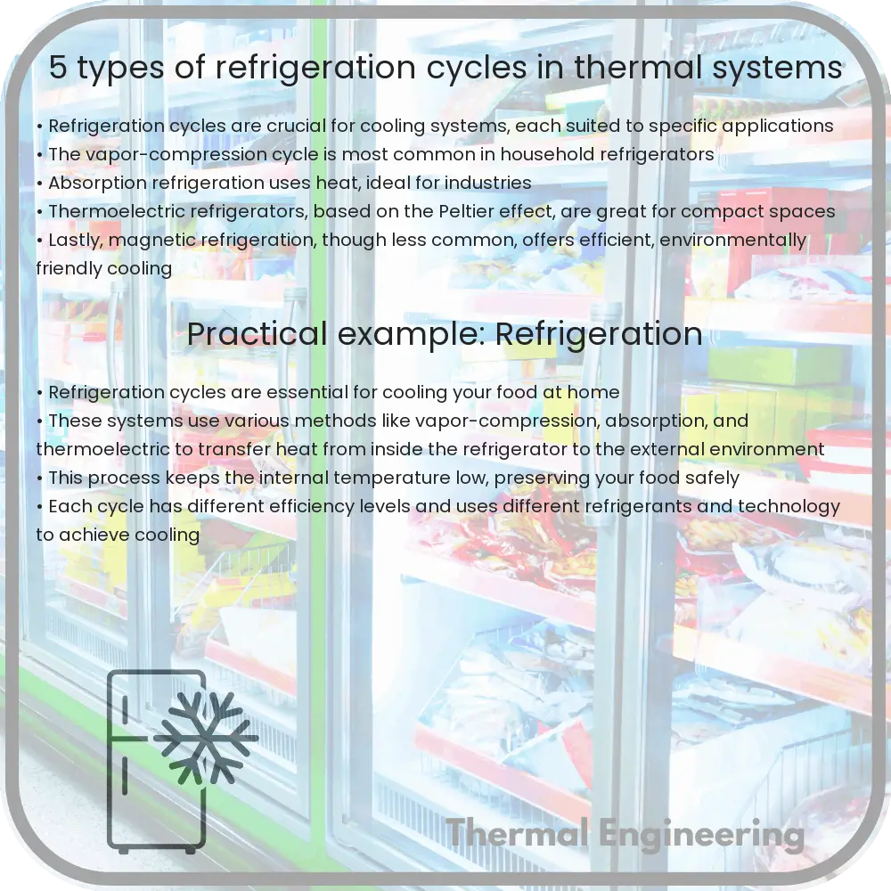
Refrigeration is a critical process used in various applications, from preserving food in our kitchens to sophisticated cooling systems in industrial processes. Central to all refrigeration systems is the refrigeration cycle, a process that removes heat from a low-temperature reservoir and transfers it to a high-temperature reservoir. The efficiency and application relevance of a refrigeration system depend largely on the type of refrigeration cycle it uses. This article explores five common types of refrigeration cycles employed in thermal systems.

1. Vapor Compression Cycle

The vapor compression cycle is the most widely used cycle for refrigeration, air conditioning, and heat pumps. This cycle uses a refrigerant in a closed loop and includes four basic components: the compressor, condenser, expansion valve (or throttle valve), and evaporator.

  • Compressor: It compresses the refrigerant, increasing its pressure and temperature.
  • Condenser: Here, the high-pressure vapor is cooled and condenses into a liquid as it loses heat to the surroundings.
  • Expansion Valve: The liquid refrigerant’s pressure is reduced as it passes through the valve, causing some of it to evaporate and cool.
  • Evaporator: The cold, low-pressure refrigerant absorbs heat from the enclosed area or substance to be cooled, turning back into a vapor.

2. Absorption Refrigeration Cycle

The absorption refrigeration cycle is similar to the vapor compression cycle, but it replaces the compressor with an absorber and a generator. These cycles typically use ammonia or water as the refrigerant and an absorbent like water or lithium bromide.

  • Absorber: It absorbs the refrigerant into the absorbent, which is then pumped to the generator.
  • Generator: Here, heating (often through external heat from gas or solar energy) separates the refrigerant from the absorbent.
  • Condenser, Expansion Valve, and Evaporator: The separated refrigerant then flows through these components similarly to the vapor compression cycle.

3. Gas Refrigeration Cycle

Gas refrigeration cycles, typically known as Bell Coleman cycles, use gas instead of a liquid refrigerant. Common in aircraft cooling systems, this cycle involves no condensation or vaporization processes. The cycle includes a compressor, a counter-flow heat exchanger (acting as a cooler), an expansion turbine, and another heat exchanger for heating.

  • Compressor: Compresses the gas, increasing its temperature and pressure.
  • Cooler: The compressed gas is cooled at constant pressure in this heat exchanger.
  • Turbine: The cool, high-pressure gas expands in the turbine, reducing its temperature and pressure.
  • Heater: The gas then absorbs heat in the second heat exchanger, repeating the cycle.

4. Steam Jet Refrigeration Cycle

Utilizing the principles of evaporation and condensation under reduced pressure, steam jet refrigeration systems are often employed where cooling loads are immense, such as in large air conditioning systems or industries.

  • Steam Ejector: Creates a vacuum that draws in the refrigerant and compresses it.
  • Evaporator: The water (commonly used as a refrigerant) boils under low pressure and temperature, absorbing the required latent heat of vaporization from the substance to be cooled.
  • Condenser: The water vapor then condenses, releasing the absorbed heat. It is recycled back into the system.

5. Thermoelectric Refrigeration Cycle

Thermoelectric refrigeration utilizes the Peltier effect, where heat is absorbed or released when electrical current passes through the junction of two different materials.

  • Peltier Module: When a DC current flows through the module, it causes one side to absorb heat and the other side to release it. This creates a temperature differential capable of cooling an isolated environment.

The selection of a refrigeration cycle is crucial and depends on factors such as energy efficiency, cost, operational requirements, and environmental impact. Each type of cycle has its specific advantages and applications, showcasing the versatility and adaptability of refrigeration technology in meeting diverse cooling needs.

12 Types of Hydraulic Turbines for Energy Generation

Learn about 12 types of hydraulic turbines used in hydroelectric power generation, each suited for specific water flow and head conditions.

12 Types of Hydraulic Turbines for Energy Generation

Understanding Hydraulic Turbines: 12 Types for Energy Generation

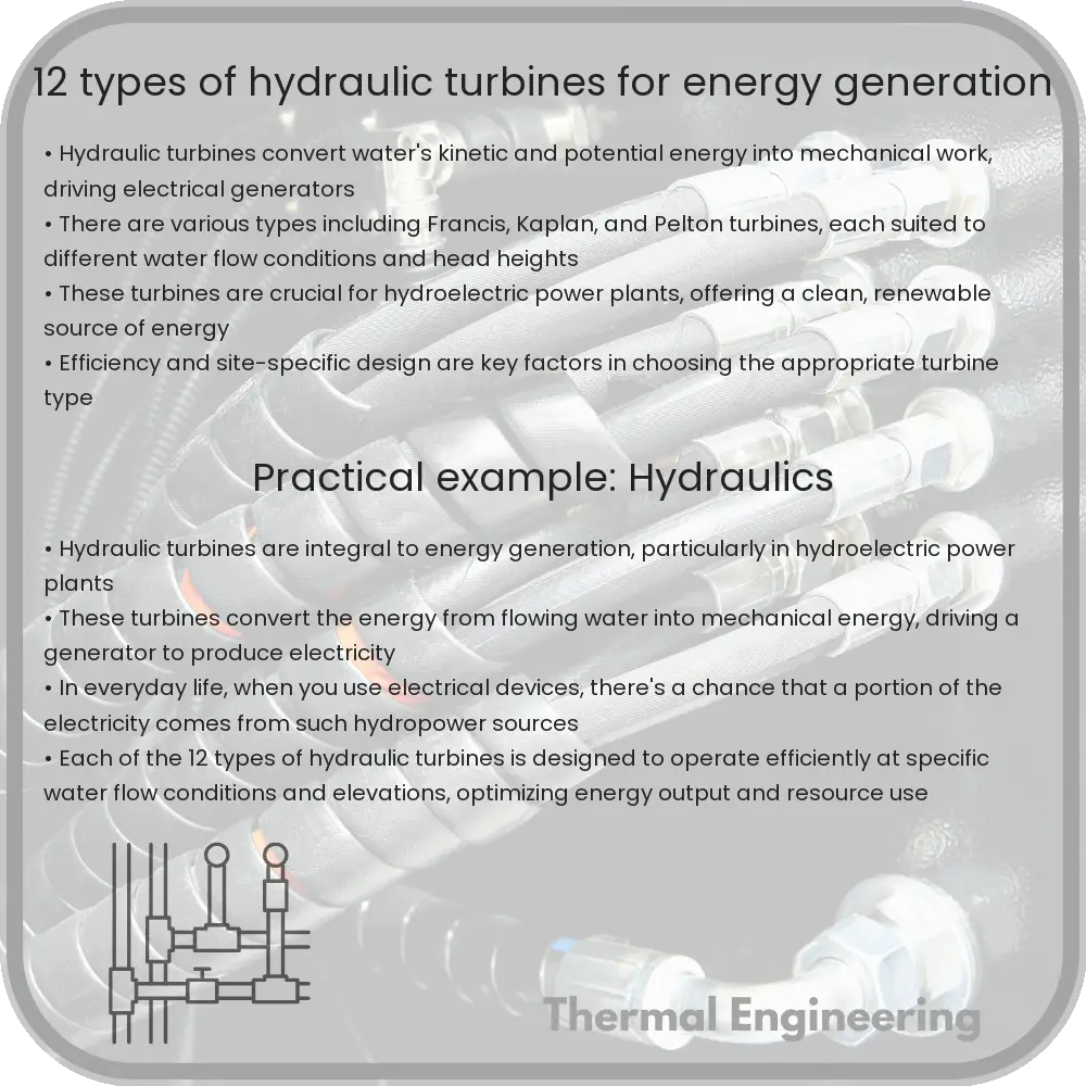
Hydraulic turbines are devices used in hydroelectric power plants to convert the energy of flowing water into mechanical energy, which is then converted into electrical energy through generators. There are several types of hydraulic turbines, each designed to operate efficiently at specific water flow rates and head conditions. In this article, we will explore 12 common types of hydraulic turbines used for energy generation.

1. Pelton Wheel

The Pelton wheel is an impulse turbine designed to operate in high-head, low-flow conditions. It features bucket-shaped blades that convert the kinetic energy of water into rotational motion. Water jets strike the blades, creating a force that causes the wheel to rotate. This type of turbine is ideal for mountainous regions where high water head is available.

2. Francis Turbine

The Francis turbine is a reaction turbine that works well under medium to high head and medium flow conditions. It has a spiral casing that directs water through vanes on a runner, causing it to spin. This turbine is one of the most common types, used widely due to its versatility and efficiency.

3. Kaplan Turbine

Kaplan turbines are reaction turbines designed for low head and high flow conditions. They feature adjustable blades that allow for optimal performance at varying flow rates. The turbine’s ability to adjust blade angles makes it particularly effective in rivers and low gradient applications.

4. Turgo Turbine

The Turgo turbine is an impulse turbine similar to the Pelton wheel but designed to handle a bit more water flow at a slightly lower head. It uses a jet of water directed at an angle to the runner, allowing for efficient energy extraction with less water volume compared to the Pelton wheel.

5. Crossflow Turbine

Also known as a Michell or Banki turbine, the Crossflow turbine features a drum-like rotor with blades that water flows through twice, enhancing efficiency. This design is effective in applications with low head and medium flow.

6. Tyson Turbine

The Tyson turbine is a variant of the Kaplan turbine, designed specifically for very low head and high flow conditions. It maximizes energy extraction in shallow rivers and streams, making it an excellent choice for small scale hydro power projects.

7. Gorlov Helical Turbine

Designed for capturing energy from flowing water in all directions, the Gorlov helical turbine has a helical shaped rotor that operates similarly to a Darrieus wind turbine. It’s particularly useful in tidal energy generation and river applications where water flow direction varies.

8. Jonval Turbine

The Jonval turbine is an older design, not commonly used today. It features vertical blades and operates under a reaction mechanism, suitable for low head and medium flow conditions.

9. Ossberger Turbine

Also known as a Banki-Crossflow turbine, the Ossberger turbine improves on the original crossflow design by maximizing efficiency and ease of maintenance. It is versatile across a range of flow conditions and is often used in small hydroelectric projects.

10. Deriaz Turbine

The Deriaz turbine, a reaction turbine similar to the Kaplan but with inclined blades, is suited for medium head and high flow conditions. Its adjustable blades enhance efficiency and control, making it suitable for varying operational requirements.

11. Bulb Turbine

The Bulb turbine incorporates a bulb-shaped housing around the generator, located directly in the water stream, typically used in tidal and low head river applications. This positioning allows for direct drive of the generator, minimizing energy losses.

12. Straflo Turbine

The Straflo turbine features a unique design where the generator is integrated into the periphery of the turbine’s rim, making it highly efficient and compact. It is typically used in low head and high flow scenarios.

Each type of hydraulic turbine has specific characteristics that make it suitable for certain environmental and operational conditions. By matching the right turbine type with the specific conditions of a hydroelectric project, engineers can maximize the efficiency and output of power generation systems.

6 Types of Turbulence Models in Fluid Dynamics

Explore various turbulence models in fluid dynamics for effective computational fluid dynamics simulations.

6 Types of Turbulence Models in Fluid Dynamics

Introduction to Turbulence Models in Fluid Dynamics

Turbulence is a fundamental phenomenon in fluid dynamics that occurs in fluids (liquids and gases) and affects various engineering and natural processes, from weather systems to the flow through pipes. In engineering, accurately predicting how turbulence behaves is crucial for designing efficient systems. Computational Fluid Dynamics (CFD), a tool used to simulate fluid flow, relies on turbulence models to approximate the effects of turbulence. These models enable engineers and scientists to predict the behavior of complex fluid flows where direct numerical simulation would be too computational expensive.

Understanding the Different Types of Turbulence Models

To manage the immense complexity of turbulent flows in computational simulations, several turbulence modeling approaches have been developed. Each model offers a different balance between computational intensity and accuracy. Here, we explore six popular types of turbulence models used in fluid dynamics.

  • Zero Equation Models
  • One Equation Models
  • Two Equation Models
  • Reynolds Stress Model (RSM)
  • Large Eddy Simulation (LES)
  • Detached Eddy Simulation (DES)

Zero Equation Models

Zero equation models, also known as algebraic models, are the simplest form of turbulence models. They do not involve solving any differential equations; instead, they use algebraic expressions to determine the turbulent viscosity. This model is based on empirically derived formulas that relate turbulent viscosity to the mean velocity gradient. A common example of a zero equation model is the Cebeci-Smith model, often used in boundary layer calculations for aerospace applications.

One Equation Models

One equation models introduce a single transport equation to calculate a turbulent property, such as the turbulent kinetic energy, k. The Spalart-Allmaras model is a widely utilized one equation model in aerodynamic applications, particularly for aerospace and automotive industries. It provides a good compromise between computational cost and accuracy for boundary layers with adverse pressure gradients.

Two Equation Models

Two equation models are more sophisticated and commonly used in CFD. These models solve two separate transport equations, typically one for the turbulent kinetic energy (k) and another for the rate of dissipation of turbulent kinetic energy (ε or ω). The most well-known two equation models are the k-ε (k-epsilon) and k-ω (k-omega) models, each having various standard and modified forms like the RNG k-ε and SST k-ω models. These models offer improved accuracy for a wide range of flows, making them suitable for industrial applications.

Reynolds Stress Model (RSM)

The Reynolds Stress Model (RSM) solves differential equations for the Reynolds stresses, along with an equation for the dissipation rate. By resolving the Reynolds stresses directly, this model can accurately predict complex flow effects such as swirls and secondary flows. However, RSMs are computationally expensive and are typically used in highly swirling or separated flows where simpler models might fail to provide good accuracy.

Large Eddy Simulation (LES)

Large Eddy Simulation (LES) is a more computationally demanding approach that resolves large-scale turbulent structures directly and models only the smaller scales. The primary challenge of LES is its significant computational cost, limiting its practical application to relatively simple geometries or smaller-scale flows. Nevertheless, for academic studies and applications where high fidelity simulations are critical, LES provides detailed insights into flow turbulence.

Detached Eddy Simulation (DES)

Detached Eddy Simulation (DES) is a hybrid model that combines elements of both RANS (Reynolds-Averaged Navier-Stokes) and LES. The model applies RANS near solid surfaces where the flow is attached, and transitions to LES in regions of large-scale separation and intense turbulence. This approach is particularly useful in capturing the unsteady behavior of large vortices in complex flows, such as those around aircraft or in the wake of vehicles.

Conclusion

The choice of a turbulence model is crucial in CFD and depends on the specifics of the flow problem being solved, including accuracy requirements, computational resources, and the particular interests of the investigation (e.g., capturing transient effects or fine-scale structures). Each type of turbulence model offers a different trade-off between computational cost and the level of detail it can resolve, making the understanding of these models essential for effective and efficient simulation work in fluid dynamics.