Facebook Instagram Youtube Twitter

How thermal diffusivity impacts heat spread

Learn about thermal diffusivity, a key property in thermal engineering that determines how quickly heat spreads through materials, affecting response time, insulation, and more.

How thermal diffusivity impacts heat spread

Understanding Thermal Diffusivity and Its Impact on Heat Spread

Thermal diffusivity is a significant property in the field of thermal engineering, representing the rate at which heat spreads through a material. It plays a crucial role in various applications, ranging from the design of building materials to the manufacturing of electronic devices. This article aims to elucidate the concept of thermal diffusivity and explore its importance in determining how heat travels within different substances.

What is Thermal Diffusivity?

Thermal diffusivity is a measure of how fast heat is conducted through a material relative to its storage of thermal energy. It is defined mathematically as:

\[ \text{Thermal Diffusivity} = \frac{k}{\rho \cdot c_p} \]

  • k is the thermal conductivity of the material (measured in watts per meter kelvin, W/(m·K)), indicating how well the material conducts heat.
  • ρ (rho) is the density of the material (in kilograms per cubic meter, kg/m3).
  • cp is the specific heat capacity (in joules per kilogram kelvin, J/(kg·K)), which represents the amount of energy required to raise the temperature of one kilogram of the material by one degree Kelvin.

The units of thermal diffusivity are square meters per second (m2/s). This property provides insight into the heat conduction rate in response to temperature changes across the material.

Impact of Thermal Diffusivity on Heat Spread

Thermal diffusivity determines how quickly a material reacts to changes in temperature, which is essential for understanding and managing heat flow in engineering applications. Below are key impacts:

  1. Response Time to Thermal Changes: Materials with high thermal diffusivity respond more rapidly to changes in temperature, making them suitable for applications requiring fast heat dissipation, such as in heat sinks and thermal management systems in electronics.
  2. Thermal Insulation: Materials with low thermal diffusivity are slower to respond to heat changes and are effective as thermal insulators. This characteristic is crucial in building construction, where maintaining temperature stability is essential.
  3. Temperature Uniformity: In processes where temperature uniformity is critical, such as in materials processing and cooking, the thermal diffusivity of the materials involved determines how evenly heat distributes throughout the substance.

Real-World Applications

The concept of thermal diffusivity is applied in numerous engineering disciplines to optimize the performance and safety of products and processes. For example:

  • In the aerospace industry, engineers select materials with appropriate thermal diffusivity to manage thermal stresses on spacecraft components exposed to extreme temperatures.
  • In the electronics industry, thermal management strategies depend on materials with high thermal diffusivity to prevent overheating of components, thus ensuring device reliability and longevity.
  • In construction, understanding the thermal diffusivity of materials can improve energy efficiency by effectively managing heat flow in residential and commercial buildings.

Conclusion

Thermal diffusivity is an essential material property that affects how heat is conducted and stored within a material, thereby influencing its temperature response. By understanding and utilizing thermal diffusivity, engineers can design more efficient, safer, and cost-effective solutions across various applications. Whether it’s choosing the right building material for insulation or selecting a suitable compound for a heat sink, thermal diffusivity remains a pivotal concept in the practical application of heat transfer principles.
How adiabatic compression heats gases

Learn how adiabatic compression increases gas temperature through pressure without heat exchange, a vital concept in thermodynamics and engineering.

How adiabatic compression heats gases

Understanding Adiabatic Compression in Gases

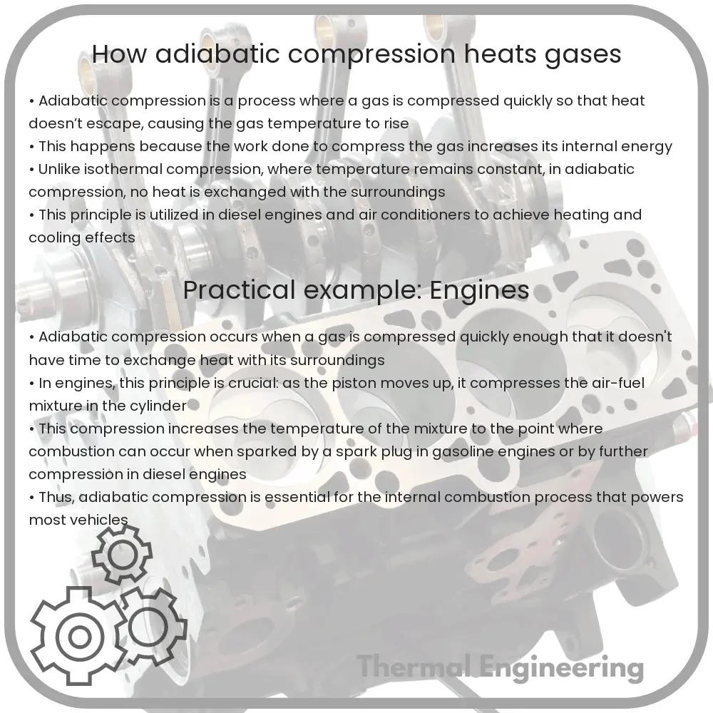
Adiabatic compression is a fundamental process in thermodynamics where the pressure of a gas is increased by compressing it, leading to a rise in temperature but without any heat transfer to or from the environment. This concept is crucial in various engineering applications, such as refrigeration cycles and internal combustion engines. To comprehend how adiabatic compression heats gases, it’s essential to first understand a few core principles of thermodynamics.

What is Adiabatic Compression?

Adiabatic compression occurs when a gas is compressed in a system that does not exchange heat with its surroundings, meaning the process is insulated against any heat transfer. As a result, all the work done on the gas is used to increase the internal energy of the gas, which raises its temperature.

The Physics Behind Adiabatic Compression

The behavior of gases undergoing adiabatic processes can be described using the ideal gas law and the concept of specific heat capacities at constant pressure (Cp) and constant volume (Cv).

  • First Law of Thermodynamics: This law states that the change in the internal energy of a system is equal to the heat added to the system minus the work done by the system. For adiabatic processes, no heat is added or removed (Q = 0), so the change in internal energy (ΔU) is simply the work done on the gas.
  • Poisson’s Equations: These equations describe the relationship between the pressure, volume, and temperature of an ideal gas during an adiabatic process. The key equations are:
    \( PV^k = \text{constant} \) and \( T V^{k-1} = \text{constant} \)
    where \( k = \frac{C_p}{C_v} \) is the specific heat ratio, a dimensionless number specific to each gas.

When you compress a gas adiabatically, you decrease its volume (V) while increasing its pressure (P). According to Poisson’s law, because the process is adiabatic, the product of pressure and volume raised to the power \( k \) remains constant. As the volume decreases, the pressure must increase proportionately such that \( PV^k \) is invariant, leading to an increase in temperature.

Real-World Applications

  • Internal Combustion Engines: In these engines, a mixture of air and fuel is compressed adiabatically in a piston chamber, greatly increasing its temperature before ignition, improving the engine’s efficiency and power output.
  • Jet Engines: Air is adiabatically compressed in the compressor section of a jet engine, raising its temperature, before it enters the combustion chamber where fuel is added, leading to more efficient fuel combustion.
  • Refrigeration Cycles: Refrigeration and air conditioning systems utilize adiabatic compression to increase the temperature and pressure of a refrigerant, which is then cooled and expanded for cooling purposes.

Conclusion

Adiabatic compression is a key phenomenon used across various engineering disciplines. By compressing gases without allowing heat exchange with the environment, significant temperature rises can be achieved. This principle is essential in designing and operating many machines that form the backbone of modern industry and technology, making it a cornerstone of engineering thermodynamics.

How thermal shock affects materials

Learn how thermal shock affects materials through rapid temperature changes, influencing their structural integrity and engineering applications.

How thermal shock affects materials

Understanding Thermal Shock in Materials

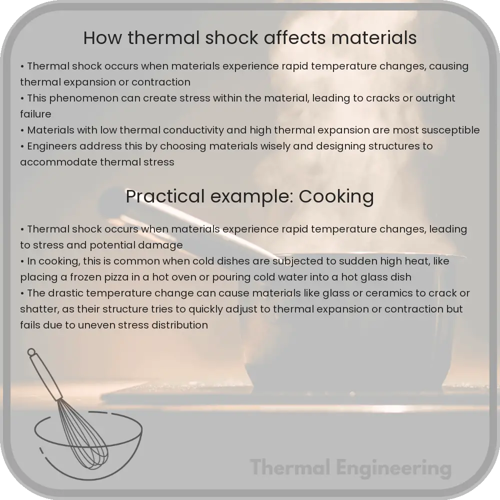
Thermal shock is a phenomenon that occurs when a material is subjected to a sudden change in temperature. This can lead to various forms of damage, such as cracking, delamination, or other structural failures. Understanding how thermal shock affects different materials is crucial in fields like materials science, engineering, and manufacturing, where materials are often exposed to varying thermal environments.

What Causes Thermal Shock?

The root cause of thermal shock is the rapid temperature fluctuation that a material experiences. When a material’s temperature changes swiftly, different parts of the material expand or contract at different rates. This uneven thermal expansion creates mechanical stress within the material, and if these stresses exceed the material’s strength, it can lead to cracks or other forms of failure.

Factors Influencing Thermal Shock Resistance

  • Thermal Conductivity: Materials with high thermal conductivity can quickly distribute the heat throughout their volume, reducing temperature gradients and the likelihood of thermal shock.
  • Thermal Expansion Coefficient: Materials with a low coefficient of thermal expansion (CTE) will undergo smaller dimensional changes with temperature shifts, thus lowering the induced thermal stress.
  • Material Strength: Higher mechanical strength and toughness can help materials resist the stresses caused by thermal expansion or contraction.
  • Temperature Gradient: The severity of the temperature change (temperature difference) and the rate at which it occurs largely determine the likelihood and severity of thermal shock.

Effects of Thermal Shock on Various Materials

Different materials respond to thermal shock in unique ways. Below are examples of common materials and how they typically handle thermal shock:

  1. Metals: Most metals have good thermal conductivity, which helps to mitigate thermal shock. However, metals with low ductility or high hardness may still be susceptible to thermal cracking under severe conditions.
  2. Ceramics: Ceramics often have high melting points and low thermal conductivity, which makes them prone to thermal shock. Their brittleness also tends to exacerbate the issue, leading to cracks or fractures under rapid temperature changes.
  3. Polymers: Polymers generally have low thermal conductivity and may deform or weaken significantly when exposed to rapid temperature changes, especially near their melting or glass transition temperatures.
  4. Glass: Like ceramics, glass suffers from poor thermal conductivity and high brittleness, making it particularly susceptible to thermal shock. This is a critical consideration in industries using glass under varying thermal conditions.

Engineering Applications and Thermal Shock

In engineering applications, the ability to design components that can withstand thermal shock is vital. This includes everything from aerospace components, which may experience extreme temperatures upon re-entry, to kitchenware like glassware or ceramic plates exposed to rapid heating. Engineers must consider the material characteristics, environmental conditions, and the expected thermal gradients when designing these products.

In conclusion, thermal shock can significantly impact the integrity and performance of materials. By understanding the factors that affect a material’s thermal shock resistance, engineers can select appropriate materials and design strategies that improve the durability and performance of products in thermally dynamic environments.

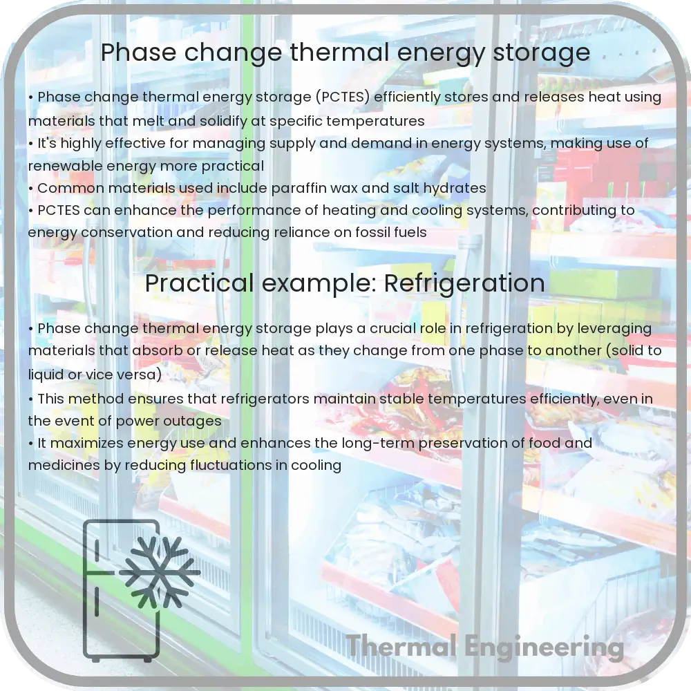
Phase change thermal energy storage

Unlock efficient energy management with Phase Change Thermal Energy Storage (PCTES), which leverages latent heat during material phase transitions.

Phase change thermal energy storage

What is Phase Change Thermal Energy Storage?

Phase Change Thermal Energy Storage (PCTES) is a type of thermal energy storage that utilizes the heat absorbed or released during a material’s phase change (e.g., from solid to liquid or vice versa) to store and recover thermal energy. This technology is key in enhancing energy efficiency in various applications, ranging from building heating and cooling to sustainable energy solutions like solar power.

How Does It Work?

The fundamental principle behind PCTES systems is the exploitation of the latent heat properties of phase change materials (PCMs). When a PCM changes its phase, it absorbs or releases a significant amount of energy at a relatively constant temperature. The most common phase change used in PCTES systems is the liquid-solid transition.

For example, during the charging process of a PCTES system, when external heat (e.g., from solar energy or excess electricity) is available, it is used to melt the PCM, thereby storing energy in the form of latent heat. Conversely, during the discharging process, the PCM solidifies and releases the stored energy, which can then be used for heating or other energy needs.

Types of Phase Change Materials

  • Organic PCM: Materials like paraffin waxes or fatty acids, which are chemically stable, non-corrosive, and exhibit negligible supercooling and good congruent melting.
  • Inorganic PCM: Substances including salt hydrates, which have higher latent heat per unit volume and better thermal conductivity but can undergo phase separation and supercooling.
  • Eutectic PCM: Combinations of organic and inorganic materials that melt and solidify at a constant temperature and have a fixed composition.

Applications of Phase Change Thermal Energy Storage

Phase change thermal energy storage finds applications in several fields:

  1. Building Energy Management: PCTES can be utilized to maintain comfortable room temperatures and reduce the load on conventional cooling and heating systems. PCM materials can be integrated into building structures like walls or floors, or used in HVAC systems.
  2. Solar Energy Systems: In solar power plants, PCTES can store excess heat generated during the day and release it during the night or overcast periods, thus stabilizing power output and increasing efficiency.
  3. Waste Heat Recovery: Industrial processes can utilize PCTES systems to store waste heat, which can later be converted into electricity or used in district heating.

Advantages and Challenges

PCTES technology offers numerous benefits:

  • High Energy Storage Density: PCMs can store 5 to 14 times more heat per unit volume than sensible heat storage materials.
  • Stable Temperature Control: The phase change occurs at nearly constant temperature, providing stability in temperature regulation applications.
  • Cost-effectiveness: While initial costs can be high, the high efficiency and durability of PCMs can lead to long-term savings.

However, there are also several challenges:

  • Cost of Materials: High-quality PCMs can be expensive, limiting their widespread implementation.
  • Integration Complexity: Retrofitting existing systems or integrating PCMTES into new designs requires significant engineering efforts.
  • Thermal Conductivity: Most PCM materials have low thermal conductivity, requiring additional engineering solutions to enhance heat transfer rates, such as adding expanded graphite or metal foams.

Conclusion

Phase Change Thermal Energy Storage represents a promising technology that can significantly contribute to the efficiency of thermal systems across various industries. Despite its challenges, ongoing research and technological improvements are making PCTES a viable option for sustainable and efficient energy management.

How Joule-Thomson effect cools gases

Learn about the Joule-Thomson Effect, the thermodynamic principle behind gas cooling and heating during expansion, crucial for refrigeration and cryogenics.

How Joule-Thomson effect cools gases

Understanding the Joule-Thomson Effect: How It Cools Gases

The Joule-Thomson effect is a fundamental principle in thermodynamics that describes the temperature change in a real gas when it is forced through a valve or porous plug while keeping it insulated so that no heat is exchanged with the environment. This phenomenon is named after James Prescott Joule and William Thomson, who first discovered it in 1852. It’s a key principle in refrigeration and various industrial processes involving gas expansion and cooling.

How the Joule-Thomson Effect Works

At the heart of the Joule-Thomson effect lies the behavior of gases when they are compressed or expanded. When a gas is forced through a restriction, like a valve, its pressure decreases. This expansion can lead to either cooling or heating, depending on the type of gas and the initial conditions.

The effect is quantified by the Joule-Thomson coefficient, µ, which is defined as the change in temperature (dT) that results from a change in pressure (dP) at constant enthalpy (H), or total heat content:

µ = (dT / dP)H

This coefficient determines whether a gas cools or heats up when expanded at constant enthalpy. If µ is positive, the gas cools down; if µ is negative, the gas heats up.

Factors Affecting the Joule-Thomson Effect

  • Type of Gas: Different gases have different Joule-Thomson coefficients at the same temperature and pressure, affecting how they heat or cool during expansion. For example, helium and hydrogen usually heat up (negative µ) under normal conditions, while gases like nitrogen and oxygen tend to cool down.
  • Temperature: The initial temperature of the gas plays a crucial role. Each gas has an inversion temperature, above which the Joule-Thomson effect causes heating instead of cooling.
  • Pressure: Higher pressures generally enhance the cooling effect for gases that have a positive Joule-Thomson coefficient below their inversion temperature.

Practical Applications

The Joule-Thomson effect is not just a theoretical principle but has practical applications in various fields:

  1. Refrigeration: It is used in gas liquefaction processes, where gases like ammonia are compressed and then allowed to expand to cool down. This process is critical in the production of liquefied gases for storage and transport.
  2. Heating Systems: For gases like hydrogen, where the effect produces heating at standard atmospheric conditions, it can be utilized in heating systems.
  3. Cryogenics: This effect is employed in cryogenic cooling systems, where gases such as nitrogen are expanded to produce very low temperatures needed in scientific experiments.

Understanding the Joule-Thomson effect is vital in designing and operating equipment that relies on controlled temperature changes of gases, whether for industrial, scientific, or consumer applications. Its thorough comprehension helps engineers and scientists innovate and maintain systems efficiently, making this phenomenon a staple concept in the fields of thermodynamics and refrigeration engineering.

How specific heat capacity varies among substances

Learn about specific heat capacity variations among materials, their impact on engineering, and how they influence the design of heating and cooling systems.

How specific heat capacity varies among substances

Understanding How Specific Heat Capacity Varies Among Substances

Specific heat capacity is a fundamental physical property that tells us how much heat energy is required to raise the temperature of a unit mass of a substance by one degree Celsius (or one Kelvin). This property is crucial in fields ranging from materials science to mechanical engineering and environmental studies. The specific heat capacity of a substance can greatly influence engineering decisions and the design of heating and cooling systems.

The value of specific heat capacity varies significantly among different materials. This variation depends on several factors including the material’s molecular structure and its state (solid, liquid, or gas). Understanding these differences is key to making informed choices in material selection and system design in engineering processes.

Factors Affecting Specific Heat Capacity

  • Molecular Structure: The way atoms and molecules are arranged in a material determines how they absorb heat. More complex molecular structures with larger atoms or more degrees of freedom typically have higher specific heat capacities because they can store more energy.
  • Phase of the Material: Generally, gases have higher specific heat capacities than liquids and solids. This is because gases require more energy to increase their temperature due to their higher freedom of movement and lower density.
  • Electron Configuration: Materials with more free electrons (such as metals) usually have lower specific heat capacities because these electrons contribute to heat transfer more efficiently than the atomic lattice.

Comparative Examples of Specific Heat Capacities

To illustrate how specific heat capacities can vary, here are a few examples:

  1. Water: Water has a high specific heat capacity at approximately 4.18 J/g·K. This is why water is an effective coolant and why it plays a critical role in climate regulation.
  2. Iron: Iron has a specific heat capacity of about 0.45 J/g·K, much lower than that of water, making it quicker to heat up and cool down, which is beneficial in applications like forging and manufacturing.
  3. Air: Dry air has a specific heat capacity around 1.01 J/g·K at constant pressure, which influences how heating and cooling systems are designed for buildings and vehicles.

Understanding the specific heat capacity of materials helps engineers design more efficient systems for heating and cooling, among other applications. Materials with high specific heat capacities are chosen for tasks that require heat absorption and retention (like thermal energy storage systems), whereas materials with low specific heat capacities are useful where quick temperature changes are desirable.

Applications in Engineering

Specific heat capacity directly impacts several engineering applications, such as:

  • Thermal Management: In systems where temperature control is critical, such as in building HVAC systems or in vehicle engine management, materials with appropriate specific heat capacities are essential.
  • Manufacturing Processes: The heating and cooling rates of materials affect the energy efficiency and quality of manufacturing processes like casting, welding, and molding.
  • Energy Storage Systems: High specific heat capacities are advantageous in systems designed to store thermal energy, such as in solar power plants or during the nighttime storage of excess heat in district heating systems.

In conclusion, the specific heat capacity is a key material characteristic that varies widely between substances. Engineers must understand and consider these variations when designing and implementing systems that involve heat and temperature control. The choice of material based on specific heat capacities can lead to more energy-efficient and effective engineering solutions.

How molten salt reactors manage heat

Learn about the efficiency of heat management in Molten Salt Reactors (MSRs), their operation, safety features, and the latest advancements in this innovative nuclear technology.

How molten salt reactors manage heat

Understanding Heat Management in Molten Salt Reactors

Molten salt reactors (MSRs) represent a class of nuclear reactors that hold significant promise due to their high efficiency and safety features. One of the critical aspects of MSR operation is the management of heat, a fundamental challenge in any nuclear reactor. MSRs offer unique solutions to heat management which leverage the properties of their primary coolant – molten salt.

How MSRs Work

Unlike traditional reactors that use solid fuel rods and water as coolant, MSRs use a fluid mixture of molten salts as both coolant and fuel solvent. This liquid fuel flows continuously through the reactor core, absorbing heat generated from nuclear fission, then circulates through a heat exchanger where the heat is transferred to a secondary coolant loop. This primary characteristic drastically alters how heat is managed in the reactor.

Heat Transfer Efficiency

The molten salt in MSRs serves both as a fuel carrier and a coolant, providing direct cooling of the reactor core. This dual role enhances heat transfer efficiency for several reasons:

  • Higher Heat Capacity: Molten salts typically have higher heat capacities than water. This allows them to absorb more heat per unit mass, resulting in more efficient heat removal from the reactor core.
  • Higher Operating Temperatures: MSRs operate at much higher temperatures compared to traditional reactors, yet under lower pressure. Since the boiling point of molten salt is much higher than that of water, MSRs can run at temperatures high enough to increase thermal efficiency without the risk of phase changes that lead to pressure build-ups.

Thermal Expansion and Reactivity Control

Thermal expansion of the molten salt plays a critical role in the inherent safety and heat management of MSRs. As the temperature increases, the density of the molten salt decreases, and it expands. This expansion can be beneficial for controlling the reactor’s reactivity. Reactivity refers to the rate at which a nuclear reaction proceeds. In MSRs, an increase in temperature generally leads to a reduction in reactivity, a safety feature termed negative temperature coefficient of reactivity. This property helps to automatically reduce the reactor power if the temperature starts to rise excessively.

Heat After Shutdown

One significant challenge in nuclear reactor operation is the management of decay heat – the heat produced by the decay of fission products after the reactor has been shut down. MSRs excel in managing decay heat due to their molten salt coolant. Because the salts retain their liquid state for some time even after the reactor is shut down, natural circulation can continue without the need for external power. This passive cooling system helps in dissipating the heat safely.

Challenges and Advances

Despite their many advantages, MSRs face certain challenges, particularly concerning the corrosive nature of molten salts at high temperatures. Ongoing research focuses on developing corrosion-resistant materials and protective coatings to enhance the longevity and safety of MSR components.

In conclusion, the way molten salt reactors manage heat represents a significant advancement in nuclear technology, offering enhanced safety, efficiency, and sustainability. As research continues and these reactors move closer to widespread commercial implementation, they could play an essential role in meeting the world’s growing energy demands while addressing safety and environmental concerns.

How thermal switches protect circuits

Learn about thermal switches, essential for circuit protection by cutting off power at high temperatures to prevent fires and equipment damage.

How thermal switches protect circuits

Understanding Thermal Switches and Circuit Protection

Thermal switches, often referred to as thermal cutoffs or thermal protectors, are crucial components in protecting electronic circuits from overheating and potential damage. These switches serve as a safeguard, cutting off electrical power when excessive temperatures are detected, thus preventing potential fire hazards and equipment failure. This article provides an overview of how thermal switches work, their types, and their role in circuit protection.

How Thermal Switches Work

Thermal switches operate based on the principles of thermal expansion or the use of materials sensitive to temperature changes. These switches consist of a sensing component that reacts to temperature by either expanding or triggering a chemical reaction. Once a preset temperature threshold is exceeded, the switch activates and either opens or closes an electrical circuit, thereby cutting or allowing power flow to protect the circuit.

Types of Thermal Switches

There are two primary types of thermal switches used in various applications:

  • Bimetallic Strips: These switches utilize two metals with different coefficients of thermal expansion welded together. When the temperature changes, the differential expansion of the metals causes the strip to bend. This bending action either opens or closes the switch, depending on the design.
  • Thermistors: These are temperature-sensitive resistors that dramatically change resistance with temperature changes. In circuit protection, thermistors can be used to limit inrush current or to trigger a response to prevent overheating.

Applications in Circuit Protection

Thermal switches find extensive applications in everyday electronics and industrial equipment, providing critical protection against overheating. Here are a few examples:

  • Home Appliances: Thermal switches are used in devices like irons, coffee makers, and hair dryers to prevent overheating that could lead to fire hazards.
  • Computers and Batteries: They are integral in managing the temperatures of CPUs, GPUs, and battery packs, cutting power when unsafe temperatures are detected to prevent damage and potential explosions.
  • Industrial Equipment: In larger machinery, thermal switches help maintain the operational safety of mechanical parts which could degrade or malfunction under high temperatures.

Benefits of Using Thermal Switches

Implementing thermal switches in circuits provides numerous benefits including:

  • Safety: Primary among the benefits is the enhancement of safety by preventing overheating and potential fires.
  • Equipment Longevity: By managing temperature extremes, thermal switches contribute to longer lifespan and better performance of electronic devices.
  • Cost-Efficiency: Protecting circuits from damage reduces the need for frequent replacements and repairs, making systems more cost-efficient in the long run.

Conclusion

Thermal switches are indispensable components in the protection of electronic circuits, offering an efficient and reliable means to handle temperature extremes. By understanding the types and functions of thermal switches, engineers and designers can integrate them into systems to ensure safe and effective operation, enhancing the durability and safety of electronic applications.

Whether you’re a student, engineer, or electronics hobbyist, recognizing the importance of these components can greatly enhance your understanding of circuit protection and thermal management in various applications.

How phase diagrams guide material science

Grasp the importance of phase diagrams for predicting material behavior in different conditions, essential for advancements in material science and engineering.

How phase diagrams guide material science

Understanding Phase Diagrams in Material Science

Phase diagrams are crucial tools in material science, providing vital information about how different materials behave under various conditions of temperature and pressure. By studying these diagrams, engineers and scientists can predict the structures of materials, optimize their fabrication processes, and innovate in the creation of new materials. This article explores the fundamentals of phase diagrams and their practical applications in material science.

What is a Phase Diagram?

A phase diagram is a graphical representation that shows the equilibrium conditions between the different phases of a material at various temperatures and pressures. Each phase represents a physically distinct state of matter, which could be solid, liquid, or gas. The phase diagram provides information about melting, boiling points, solubility, and other critical material properties.

Key Components of Phase Diagrams

  • Axis: Typically, the horizontal axis represents temperature, while the vertical axis represents pressure.
  • Phase boundaries: Lines on the diagram that divide different phases. At these boundaries, two phases coexist in equilibrium.
  • Critical Point: The point on a phase diagram where the distinction between liquid and gas phases disappears.
  • Triple Point: The point where three phases (solid, liquid, and gas) coexist in equilibrium.

Types of Phase Diagrams

Phase diagrams can be categorized based on the number of components they represent:

  1. Unary Phase Diagrams: These diagrams represent the phases of a single component over different temperatures and pressures.
  2. Binary Phase Diagrams: These diagrams show the phase behavior of two-component mixtures. They are essential in industries where alloys and compound formulations are critical.
  3. Ternary Phase Diagrams: Useful in studying systems with three different components. These are more complex and are crucial in the study of ceramics and polymeric materials.

Applications of Phase Diagrams in Material Science

Phase diagrams are used extensively in material science for various applications:

  • Material Design: By understanding the temperature and pressure at which different phases occur, engineers can tailor materials for specific applications, such as superalloys for jet engines that operate at high temperatures.
  • Quality Control: Phase diagrams help in identifying the causes of failures in materials, such as corrosion, by understanding the environmental conditions that can lead to such issues.
  • Research and Development: Scientists use phase diagrams to discover new material combinations, predict material behavior under extreme conditions, and innovate in techniques such as cryogenic treatment or heat treatment.

Conclusion

Phase diagrams are more than just scientific charts; they are fundamental tools that drive innovation in material science. By mapping out the conditions under which various phases of materials exist, phase diagrams allow scientists and engineers to push the boundaries of what is possible with materials. Whether it is optimizing steel’s performance or creating novel, high-performance materials, understanding phase diagrams is essential for advancing technology and engineering.

How radiant floor heating distributes warmth

Learn about radiant floor heating, an efficient home heating system that distributes warmth evenly through electric cables or hot water tubes installed under the floor.

How radiant floor heating distributes warmth

Understanding How Radiant Floor Heating Distributes Warmth

Radiant floor heating is a method of heating a space that delivers heat directly from the floor. It is well appreciated for its efficiency and the uniform warmth it provides in a home or building. In this article, we’ll explore how radiant floor heating systems work, the types of installations available, and the principles behind their efficient heat distribution.

Types of Radiant Floor Heating Systems

There are mainly two types of radiant floor heating systems:

  • Electric Radiant Floors: These systems use electric cables built into the floor. They are typically installed over a thermal mass such as a concrete slab, which acts as a heat sink, absorbing the heat and releasing it slowly.
  • Hydronic Radiant Floors: These systems are more commonly used in whole-house heating. They utilize a network of polyethylene tubing that runs under the floor through which hot water is circulated. The water is usually heated by boilers or solar water heaters.

How Heat is Distributed in Radiant Floor Heating

Radiant floor heating systems distribute heat via the process of radiation. This is fundamentally different from traditional heating systems like forced air heating, which use convection (the movement of air) to distribute heat. Here’s how the radiant floor heating efficiently warms up a space:

  1. Heat Production: In electric systems, when the thermostat signals a need for heating, electricity heats up the cables under the floor. In hydronic systems, the boiler or solar water heater raises the temperature of the water, which then circulates through the tubing.
  2. Heat Transfer: The heat from the cables or heated water radiates upward from the floor, warming the nearby air and objects directly. This is a key aspect as the heat is transferred to the objects in the room, including furniture, which then radiate heat as well.
  3. Even Heat Distribution: Since the heating elements (cables or tubes) are spread out across the floor, the warmth is distributed evenly across the entire surface. This uniform distribution ensures that there are no cold spots in the room.
  4. Heat Retention: Materials typically used for flooring in these systems, like concrete, tile, or stone, have high thermal mass, meaning they absorb and retain heat well. This property allows the floor to store heat and release it slowly, maintaining a consistent temperature over time.
  5. Minimizing Heat Loss: Radiant floor heating systems are installed with insulation beneath the heating elements to prevent heat from flowing downwards. This maximizes the efficiency of the system by directing the heat upwards into the living space.

The Advantages of Radiant Floor Heating

Radiant floor heating offers several benefits over other heating methods:

  • Comfort: The heat is distributed evenly and rises gently, warming a space more uniformly which can feel more comfortable than the sometimes uneven heat from radiators and air vents.
  • Energy Efficiency: Radiant heating can be more energy-efficient, as it directly heats objects and people, and allows lower thermostat settings while achieving the same level of comfort.
  • Improves Air Quality: Unlike forced-air systems that can distribute allergens and dust along with heat, radiant floor heating doesn’t circulate air, thus contributing to better indoor air quality.

Understanding the basic operation and benefits of radiant floor heating helps in appreciating why it is considered a desirable home heating option. It provides a silent operation, can be more energy-efficient, and offers a comfortable heating alternative to traditional systems. Whether used for specific areas like bathrooms or throughout an entire home, radiant floor heating continues to be a popular choice for those seeking a cozy yet efficient heating solution.