Facebook Instagram Youtube Twitter

How thermal expansion affects structures

Learn about thermal expansion and its importance in engineering, from the basics of how materials react to temperature changes to strategies for mitigating its impact on structures.

How thermal expansion affects structures

Understanding How Thermal Expansion Affects Structures

Thermal expansion refers to the tendency of matter to change its shape, area, and volume in response to a change in temperature. This concept is crucial in engineering and construction because it affects materials used in buildings, bridges, railways, and other infrastructure. Ignoring thermal expansion can lead to failed components and even safety hazards. Here, we will explore how thermal expansion impacts structures and the engineering principles used to mitigate its effects.

Basic Principles of Thermal Expansion

Most materials expand when heated and contract when cooled. The degree of this expansion or contraction is characterized by the material’s coefficient of thermal expansion (CTE), which is typically expressed as a fractional change in size per degree change in temperature (e.g., 1/C°). For instance, metals generally have higher CTEs than ceramics or composites. Understanding and calculating this expansion is essential for designing structures that can withstand temperature variations.

The formula used to calculate the linear expansion of an object is:

\[ \Delta L = \alpha L_0 \Delta T \]

  • \(\Delta L\): Change in object length
  • \(\alpha\): Coefficient of thermal expansion
  • \(L_0\): Original length of the object
  • \(\Delta T\): Change in temperature

Examples of Thermal Expansion in Structures

Everyday examples of thermal expansion can be seen in structures like bridges and railways:

  • Bridges: To allow for thermal expansion, engineers design bridges with expansion joints. These joints accommodate the expansion and contraction of materials, preventing structural damage. For instance, the steel beams used in bridges can expand several inches over their length during summer, and without expansion joints, this could lead to buckling, structural failure, or increased stress in other components.
  • Railways: Railroad tracks are also subject to significant thermal expansion. The tracks are laid with small gaps between the sections of rails, allowing them enough space to expand in hot weather without causing buckling or derailing trains.

Materials with High vs. Low Coefficient of Thermal Expansion

The choice of building material is significantly influenced by its thermal properties, especially the coefficient of thermal expansion. Here’s how different materials behave:

  • Metals: Aluminium, steel, and other metals have high CTEs and thus are more susceptible to expanding in heat and contracting in cold.
  • Composites and Ceramics: These materials generally have lower CTEs, meaning they experience less dimensional change with temperature fluctuations, making them suitable for applications requiring high dimensional stability under varying temperatures.

Mitigation Strategies for Thermal Effects

Engineers implement various strategies to mitigate the impacts of thermal expansion in construction and design:

  • Using materials with compatible thermal expansion properties: Careful selection of materials that expand and contract similarly can reduce stresses and deformations in composite structures.
  • Thermal barriers and insulations: Incorporating thermal barriers and insulation can regulate the temperatures that materials are exposed to, thus limiting thermal expansion and contraction.
  • Structural adjustments: Designing components with tolerances for expected thermal expansion allows structures to adapt to temperature changes without damage.

Conclusion

Understanding thermal expansion and its effects on materials is critical in engineering. By accurately calculating expected expansions and designing structures to accommodate these changes, engineers can ensure the safety, reliability, and longevity of structures. Whether it’s a bridge, a skyscraper, or a railroad track, accounting for thermal expansion is a fundamental aspect of the design and construction process that cannot be overlooked.

How heat exchangers optimize energy use

Learn about heat exchangers, their types, operation principles, and role in energy optimization for various industrial applications.

How heat exchangers optimize energy use

Understanding Heat Exchangers and Energy Optimization

Heat exchangers are devices designed to transfer heat between two or more fluids—liquids, vapors, or gases—of different temperatures. Depending on the type of heat exchanger employed, the fluids may be separated by a solid wall to prevent mixing or may be in direct contact. Heat exchangers are commonly used in various applications, including refrigeration, air conditioning systems, power plants, chemical processing, and automotive industries.

Types of Heat Exchangers

  • Shell and Tube Heat Exchangers: These consist of a series of tubes. One set of these tubes contains the fluid that must be either heated or cooled. The second fluid runs over the tubes that are being heated or cooled so that it can either provide the heat or absorb the heat required.
  • Plate Heat Exchangers: This type uses metal plates to transfer heat between two fluids. Plate exchangers are generally more efficient than shell and tube types because they have a larger surface area for heat transfer.
  • Regenerative Heat Exchangers: These allow the hot and cold fluids to flow through the same space with a temporal displacement, effectively storing heat and then releasing it to the colder fluid. This type is particularly useful in applications where heat recovery is desirable.

Principle of Operation

Heat exchangers operate on the principle of heat transfer by convection, conduction, or a combination of these methods. The general principle guiding the operation of heat exchangers is that more surface area increases heat transfer but also requires more space and material, which can increase costs. Efficient heat exchanger design aims to balance these factors to achieve maximum energy efficiency.

Optimizing Energy Use

Energy efficiency in heat exchangers is crucial for reducing operational costs and minimizing environmental impact. The efficiency of a heat exchanger is influenced by several factors:

  1. Temperature Difference: The greater the temperature difference between the hot and cold fluids, the more effective the heat transfer process tends to be. This is described by the logarithmic mean temperature difference (LMTD), calculated by \frac{(\Delta T_1 – \Delta T_2)}{\ln(\Delta T_1/\Delta T_2)}, where \(\Delta T_1\) and \(\Delta T_2\) are the temperature differences at each end of the exchanger.
  2. Flow Arrangement: In counterflow heat exchangers, the fluids flow in opposite directions. This arrangement usually provides the most efficient heat transfer because it can maintain a higher average temperature difference throughout the exchanger.
  3. Surface Area and Heat Transfer Coefficient: Increasing the surface area or improving the heat transfer coefficient through surface treatments or altering the flow dynamics can significantly enhance a heat exchanger’s performance.
  4. Maintenance: Fouling, which is the accumulation of unwanted materials on the heat transfer surfaces, reduces overall thermal performance and efficiency. Regular cleaning and maintenance are essential for optimal operation.

Applications in Energy Systems

Heat exchangers are integral to modern energy systems both for heating and cooling applications and for enhancing energy efficiency. For instance:

  • In power plants, heat exchangers are used to capture and reuse waste heat from hot exhaust gases, significantly improving the efficiency of electrical power generation.
  • In HVAC (Heating, Ventilating, and Air Conditioning) systems, heat exchangers are used to transfer heat from indoor air to the outside in cooling applications and vice versa in heating applications.
  • Heat exchangers in refrigeration systems help to efficiently move heat away from the area being cooled.

By understanding the fundamentals of how heat exchangers work and are applied, engineers can design systems that maximize energy efficiency, reduce costs, and impact environmental sustainability positively.

How does a cooling curve inform material science

Learn how cooling curves impact material properties during phase transitions, essential for metallurgy and manufacturing.

How does a cooling curve inform material science

Understanding Cooling Curves in Material Science

In material science, the study of cooling curves is crucial for understanding the properties and behaviors of different materials as they transition from liquid to solid. These curves provide valuable insights into the crystallization and solidification processes, which are fundamental for applications in metallurgy, manufacturing, and materials engineering.

What is a Cooling Curve?

A cooling curve is a plot of temperature versus time, which illustrates how a substance cools and transitions from a higher energy state to a lower energy state. For materials transitioning from the liquid phase to the solid phase, this curve can reveal significant transformations such as the temperatures at which various phases occur, the rate of cooling, and the effects of cooling on material structure.

Key Features of Cooling Curves

  • Temperature Plateaus: During the cooling of a pure substance, the temperature remains constant for a period when the material changes phase. This plateau indicates the release of latent heat as the material transitions from liquid to solid.
  • Rate of Cooling: The slope of the cooling curve can indicate the rate at which heat is being removed from the substance. A steeper slope suggests a faster cooling rate, which can affect the crystal structure and mechanical properties of the final solid.
  • Undercooling: Sometimes, the temperature of a liquid can drop below its normal solidification point without transitioning into a solid—a phenomenon known as undercooling. The extent of undercooling can influence the nucleation and growth of crystals.

Cooling Curve Analysis for Different Materials

Different materials exhibit unique cooling curves depending on their composition, impurities, and cooling conditions. For instance, metals and alloys might show complex cooling behaviors due to the presence of multiple phases and constituents. The analysis of these curves allows scientists and engineers to tailor cooling processes to optimize material properties such as toughness, ductility, and strength.

Practical Applications

  1. Metallurgy: Cooling curves are instrumental in metallurgy for controlling the microstructure of metals and alloys. By adjusting the cooling rate, metallurgists can influence the size and distribution of crystals in the solidified material, affecting its physical properties.
  2. Plastic Manufacturing: In plastic manufacturing, cooling curves help in determining the crystallization behavior of polymers. This is essential for ensuring the stability and performance of plastic products under different conditions.
  3. Quality Control: Cooling curve analysis is also used for quality control in various manufacturing processes. It ensures that the thermal treatments are consistent and that the materials meet the required specifications and performance criteria.

Conclusion

Cooling curves are a fundamental tool in material science, providing a deeper understanding of material behaviors and transformations during the cooling process. By studying these curves, scientists and engineers can manipulate material properties to suit specific applications, improving product performance and functionality across various industries. This knowledge not only enhances the material design and selection process but also plays a crucial role in advancing technology in materials engineering.

How thermosiphon systems circulate without pumps

Learn how thermosiphon systems use thermal physics and natural convection to circulate fluids and transfer heat without mechanical pumps in various applications.

How thermosiphon systems circulate without pumps

Understanding Thermosiphon Systems: Circulation Without Pumps

Thermosiphon systems are a fascinating application of thermal physics and fluid dynamics that allow liquid circulation without the need for mechanical pumps. This passive heat exchange method is used in a variety of applications, from residential water heaters to large-scale industrial processes. Understanding how these systems work provides a great window into practical engineering principles applied in everyday technology.

Principles of Operation

The operation of a thermosiphon system is based on the principle of natural convection, which occurs when a fluid such as water or oil heats up, becomes less dense, and rises because of the gravitational force acting on the density differences in the fluid. As the fluid cools down, it becomes denser and sinks naturally, creating a continuous flow cycle that can effectively transfer heat from one place to another without the need for a mechanical pump.

The Components of a Thermosiphon System

  • Heat Source: This is where the fluid in the system is heated, causing it to expand and reduce in density.
  • Riser Tube: As the fluid warms up, it rises through this vertical tube due to its reduced density compared to the surrounding cooler fluid.
  • Heat Exchanger/Radiator: At the top of the cycle, the fluid releases its heat. After releasing the heat, the fluid cools, increasing in density.
  • Downcomer Tube: The cooled fluid returns to the lower part of the system through this tube, completing the circulation loop.

Thermodynamics Behind Thermosiphon Systems

Understanding the thermodynamics of thermosiphon systems involves examining the heat transfer and fluid flow within the system. The driving force behind the fluid flow is the density difference induced by temperature changes, governed by the equation:

Δρ = ρ0(1 – βΔT)

where:

  • Δρ is the change in density
  • ρ0 is the initial density of the fluid
  • β is the volumetric temperature expansion coefficient of the fluid
  • ΔT is the temperature difference

This equation highlights how the change in density varies inversely with the change in temperature, facilitating natural circulation as the warmer, less dense fluid rises and the cooler, denser fluid sinks.

Applications of Thermosiphon Systems

  • Solar Water Heaters: One of the most common uses of thermosiphon systems is in solar water heating, where solar energy is used to heat water without electricity.
  • Radiant Floor Heating: These systems can also be applied in radiant floor heating, where the circulated hot water warms the floor surface evenly.
  • Industrial Cooling: In industries, thermosiphon systems are used for cooling purposes, such as in the cooling of power station transformers.

Advantages of Using Thermosiphon Systems

Thermosiphon systems are favored in many applications due to their simplicity and efficiency. They are cost-effective, as they do not require electric pumps or complex mechanical parts. Moreover, these systems are low maintenance and can operate in power-outage scenarios, providing an environmentally friendly solution that utilizes natural convection principles.

In summary, thermosiphon systems exemplify how basic physics principles can be ingeniously applied in practical scenarios to achieve efficient and sustainable engineering solutions. By leveraging the natural propensity of heated fluids to rise, these systems facilitate effective heat transfer without the need for mechanical aids, highlighting the elegance and efficiency of passive engineering designs.

How pyrolytic heating decomposes materials

Gain insights on pyrolytic heating—a thermal decomposition process used in producing biochar, synthetic gases, and other materials without oxygen.

How pyrolytic heating decomposes materials

Understanding Pyrolytic Heating: A Guide to Material Decomposition

Pyrolytic heating is a fundamental process used in various industrial and scientific fields. Essentially, it refers to the thermal decomposition of materials at elevated temperatures in the absence of oxygen. This process is crucial for understanding how materials break down under heat and is used to produce a range of products from biochar to synthetic gases. In this article, we will explore the basics of pyrolytic heating, how it works, and its common applications.

What is Pyrolytic Heating?

Pyrolytic heating, or simply pyrolysis, involves heating materials to high temperatures, typically between 200°C and 700°C, in an environment devoid of oxygen. Without oxygen, the material does not combust but instead breaks down chemically, producing various types of gases, liquids, and a solid residue. The specific products depend on the material being heated and the conditions under which pyrolysis occurs.

The Pyrolytic Process

The process of pyrolysis can be divided into three main stages:

  1. Drying and Devolatilization: Initially, any moisture present in the material is evaporated. Following this, the material’s volatile components are released as the temperature increases.
  2. Decomposition: As the temperature continues to rise, the long chains of hydrocarbons begin to break down. This chemical breakdown leads to the formation of smaller molecules typically in the form of gases, tar, and oil.
  3. Carbonization: At higher temperatures and longer dwelling times, the material is converted into carbon (char or biochar) and light gases. This stage is also accompanied by the redistribution of elements like hydrogen, oxygen, and nitrogen, which were originally part of the material.

The chemical reactions involved in pyrolysis are endothermic, meaning they absorb heat. The efficiency and yield of the process can be influenced by factors such as temperature, heating rate, pressure, and the particle size of the material.

Applications of Pyrolytic Heating

Pyrolytic heating has a wide range of applications across various industries:

  • Production of Charcoal: Wood and other biomass are pyrolyzed to produce charcoal, used both as a fuel and a reduction agent in metal smelting.
  • Energy Production: The gases and oils generated from pyrolysis can be used as fuels. For example, pyrolysis oil can substitute for furnace oil or diesel.
  • Chemical Industry: Pyrolysis is also used in the chemical recycling of plastics back into their original monomers or converting them into synthetic gases and oils.
  • Agricultural Enhancements: Biochar produced from biomass pyrolysis can enhance soil fertility and sequester carbon, reducing greenhouse gases.

Understanding pyrolytic heating and its applications not only provides insight into material behavior under extreme conditions but also offers opportunities for innovation in recycling, energy production, and beyond.

Conclusion

Pyrolytic heating is a critical process in engineering and materials science, breaking down complex materials through the application of heat in an oxygen-free environment. By controlling this process, engineers can create useful products while also contributing to sustainable practices in energy and materials management. Whether in creating fuels, enhancing soil, or recycling waste materials, pyrolysis plays a vital role in advancing our capabilities and understanding of material transformation.

How thermal bridges impact building performance

Learn how thermal bridges impact energy efficiency and comfort in buildings, their types, effects, and strategies for mitigation.

How thermal bridges impact building performance

Understanding Thermal Bridges and Their Impact on Building Performance

Thermal bridges are areas in a building where heat flows more readily compared to the surrounding materials, fundamentally altering the energy efficiency of the structure. These bridges occur when materials that are poor insulators, or conduct heat well, come in contact, allowing heat to bypass the insulative layers of a building. Understanding and mitigating thermal bridges is crucial for enhancing building performance, particularly in terms of energy efficiency and thermal comfort.

Types of Thermal Bridges

Thermal bridges can be classified into three main types:

  • Repeating Thermal Bridges: These occur when materials with high thermal conductivity span across the insulation layer repeatedly, such as metal fasteners or studs in a wall.
  • Non-repeating Thermal Bridges: These occur infrequently and are often due to disruptions in the building’s envelope like windows, doors, or service openings.
  • Geometric Thermal Bridges: These are shaped by the design of the building itself, where the shape of the building can create areas with increased heat flow, such as corners or edges where different sections of a building meet.

Effects of Thermal Bridges on Building Performance

The presence of thermal bridges in a building can lead to several undesirable outcomes:

  • Increased Energy Consumption: Heat loss or gain through thermal bridges can lead to higher energy usage to maintain comfortable interior temperatures, negatively impacting energy efficiency and increasing utility costs.
  • Comfort Issues: Uneven temperatures throughout a building caused by thermal bridges can create cold spots in winter and hot spots in summer, reducing occupant comfort.
  • Condensation Risks: Thermal bridging can cause surface temperatures to drop below the dew point, leading to condensation. This can result in mold growth and structural damage over time.

Measuring and Calculating the Impact of Thermal Bridges

The impact of thermal bridges is quantified using the thermal transmittance, or U-value, and the linear thermal transmittance, or ψ-value (psi-value). The U-value measures the overall rate of heat transfer through a complete structure, considering all layers and materials, expressed in watts per square meter-kelvin (W/m²K). The ψ-value accounts specifically for the additional heat flow through the thermal bridge, expressed in watts per meter-kelvin (W/mK).

The total heat transfer due to thermal bridging can be calculated with the equation:

Q = L * ψ * ΔT

Where:

  • Q is the heat flow rate through the thermal bridge (in watts, W)
  • L is the length of the thermal bridge (in meters, m)
  • ψ is the linear thermal transmittance (in W/mK)
  • ΔT is the temperature difference across the building envelope (in Kelvins, K)

Strategies for Mitigating Thermal Bridges

To enhance building performance and minimize the detrimental effects of thermal bridges, several strategies can be employed:

  • Thermal Break Materials: Installing materials that have low thermal conductivity at junctions or where different materials meet can reduce the effects of thermal bridges.
  • Improved Design and Construction: Designing buildings with minimal projections and interruptions in the insulation layer and using construction techniques that reduce direct connections made of highly conductive materials.
  • Enhanced Insulation Techniques: Adding extra insulation at known points of thermal bridging can help in minimizing heat loss or gain.
  • Thermal Imaging: Using thermal imaging to identify existing thermal bridges in buildings can help in targeting improvements and verifying the effectiveness of interventions made to reduce thermal bridging.

By effectively addressing thermal bridges, engineers and architects can significantly enhance a building’s energy efficiency, durability, and comfort for occupants. This makes understanding and mitigating thermal bridges a critical aspect of modern building design and performance optimization.

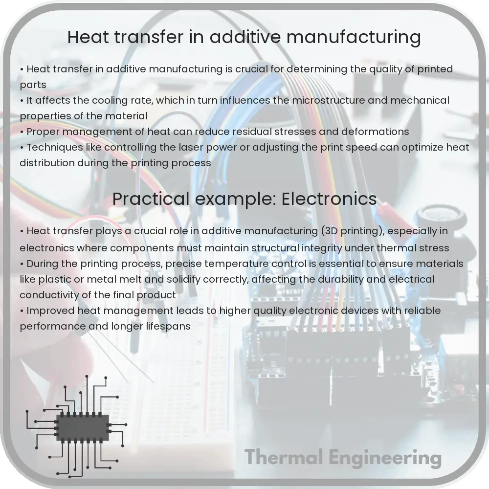
Heat transfer in additive manufacturing

Learn about heat transfer’s role in additive manufacturing, including conduction, convection, radiation, and their impact on 3D printing quality and efficiency.

Heat transfer in additive manufacturing

Understanding Heat Transfer in Additive Manufacturing

Additive manufacturing, more commonly known as 3D printing, is a revolutionary approach to fabricating objects layer by layer from a digital model. One critical aspect of this technology is the management of heat transfer during the printing process. Heat transfer affects the quality, efficiency, and physical properties of the final product. In this article, we explore how heat transfer occurs in additive manufacturing and its implications.

Types of Heat Transfer in Additive Manufacturing

In additive manufacturing, heat transfer primarily occurs through conduction, convection, and radiation. Each plays a pivotal role depending on the material and the specific technology used:

  • Conduction: This is the transfer of heat through materials that are in direct contact. In 3D printing, this happens between the layers of material as they are deposited and fused together.
  • Convection: In processes where a heat source like a laser or electron beam is used, convection can occur due to the movement of air or protective gases around the print area.
  • Radiation: Radiative heat transfer may occur from the heat source to the material being printed, especially in metal additive manufacturing where high temperatures are involved.

Critical Factors Impacting Heat Transfer

Several factors influence the efficiency and dynamics of heat transfer during the printing process:

  • Material Properties: Different materials, such as polymers, metals, and ceramics, have distinct thermal properties like thermal conductivity, specific heat capacity, and emissivity.
  • Layer Thickness: The thickness of each layer affects how quickly heat is conducted through the material. Thinner layers may cool faster, potentially influencing the bond between successive layers.
  • Printing Environment: Temperature, ambient pressure, and the presence or absence of inert gases can affect convection and cooling rates.
  • Energy Source: The intensity, focus, and duration of the energy applied (laser, electron beam, etc.) greatly influence localized heating and cooling.

Challenges and Solutions in Heat Management

Improper management of heat transfer can lead to defects such as warping, residual stresses, and poor mechanical properties. Addressing these challenges involves several strategies:

  • Optimizing Print Parameters: Adjusting factors like the power of the heat source, print speed, and layer thickness can help manage the heat distribution and mitigate defects.
  • Using Thermal Simulation: Computer simulations can predict how heat will affect a part during printing, allowing for adjustments before actual production.
  • Post-Processing: Techniques such as heat treatment and annealing can be used post-printing to relieve residual stresses and improve the structural integrity of a printed object.

Future Directions

As additive manufacturing technologies evolve, understanding and controlling heat transfer will remain crucial. Advances in thermal imaging and real-time monitoring could lead to better control systems that dynamically adjust printing parameters for optimal heat management. Additionally, the development of new materials with tailored thermal properties could expand the applicability of 3D printing across various industries.

In summary, heat transfer in additive manufacturing is a complex yet critical aspect that requires careful consideration and management to optimize the quality and functionality of printed objects. With ongoing research and technological advancements, the strategies for managing heat transfer are continually improving, pushing the boundaries of what can be achieved with this transformative technology.

How thermodynamic cycles power engines

Learn about thermodynamic cycles and their role in powering engines, from basic principles to efficiency limits governed by the second law of thermodynamics.

How thermodynamic cycles power engines

Understanding How Thermodynamic Cycles Power Engines

Thermodynamic cycles are the backbone of modern engine technology, converting the energy stored in fuel into usable mechanical work. This article explains the basic principles of thermodynamic cycles and how they power engines in a way that is easy to understand.

What is a Thermodynamic Cycle?

A thermodynamic cycle consists of a series of processes that involve the transfer and transformation of energy. In the context of engines, these cycles involve the compression, combustion, expansion, and exhaust of a working fluid—typically air mixed with fuel. The goal of these cycles is to convert the chemical energy in the fuel into mechanical energy that can move a vehicle, generate electricity, or power industrial machinery.

Key Processes in Thermodynamic Cycles

  • Compression: The working fluid is compressed, increasing its pressure and temperature, and making it more reactive to ignition.
  • Combustion: Fuel is injected into the compressed air, igniting it. The combustion process releases a large amount of heat, which raises the temperature and pressure of the gas substantially.
  • Expansion: This high-pressure, high-temperature gas then expands within the engine. As it expands, it pushes against mechanical components of the engine (like pistons or turbine blades), converting the energy from the pressure and temperature into mechanical work.
  • Exhaust: After the energy has been extracted from the gas, the exhaust process expels the spent gases out of the engine, making room for fresh air to start a new cycle.

Common Thermodynamic Cycles in Engines

There are several common thermodynamic cycles used in different types of engines:

  1. Otto Cycle: Used in most gasoline engines, involves a spark ignition.
  2. Diesel Cycle: Used in diesel engines, where ignition occurs due to high temperature from compression alone.
  3. Brayton Cycle: Utilized in jet engines and gas turbines, characterized by continuous intake and exhaust of air.
  4. Rankine Cycle: Often used in power plants and ships, involving a liquid-to-vapor phase change, generally using water.
  5. Stirling Cycle: Found in some external combustion engines and coolers, known for its high efficiency in some applications.

The Second Law of Thermodynamics and Engine Efficiency

The second law of thermodynamics states that the total entropy of an isolated system can never decrease over time. This law is particularly important in understanding engine efficiency, which is governed by the Carnot efficiency limit. The Carnot efficiency is given by:

ηCarnot = 1 – (Tc / Th)

where Tc is the temperature of the cold reservoir and Th is the temperature of the hot reservoir. In practical terms, this equation tells us that no engine can convert all of its heat energy into mechanical energy—there will always be some loss in the form of waste heat.

Conclusion

Thermodynamic cycles provide the fundamental framework for understanding how engines convert fuel into mechanical energy. By understanding these cycles, engineers can design more efficient engines that are capable of doing more work with less fuel and producing fewer emissions. Whether in cars, power plants, or aircraft, the principles of thermodynamics play a crucial role in powering the machines that make modern life possible.

With ongoing research and development in materials and technology, the future of engine design promises even greater efficiency and reduced environmental impact, all thanks to the application of thermodynamic principles.

How heat recovery ventilation conserves energy

Learn how Heat Recovery Ventilation (HRV) systems efficiently exchange air, conserve energy, and improve indoor quality in buildings.

How heat recovery ventilation conserves energy

Understanding Heat Recovery Ventilation: A Path to Energy Conservation

Heat recovery ventilation (HRV) systems offer an efficient way to exchange air inside a building while minimizing energy loss. This technology is particularly important in airtight spaces where maintaining air quality without excessive energy consumption poses a challenge. By understanding how HRV systems work and their benefits, we can appreciate their role in conserving energy in residential and commercial buildings.

How Does a Heat Recovery Ventilation System Work?

At its core, an HRV system consists of two separate air streams—outgoing stale indoor air and incoming fresh outdoor air. The magic of HRV lies in its ability to transfer heat from the warmer air stream to the cooler one without mixing the two. This exchange is facilitated by a heat exchanger unit.

  • Exhaust air heat transfer: As the warm indoor air is expelled from the building, it passes through one side of the heat exchanger. Despite leaving, its thermal energy is not wasted.
  • Incoming air preheating: Simultaneously, cold fresh air flows through the opposite side of the heat exchanger, where it absorbs the heat from the exhaust air. This process preheats the incoming air before it enters the living spaces.

The result is a remarkable maintenance of indoor temperatures with significantly reduced demand on heating systems during cold months, and similarly reduced cooling requirements during warm months. By recovering typically lost energy, HRV systems can achieve energy recovery efficiency rates upwards of 70-90%.

Benefits of Heat Recovery Ventilation

  • Energy savings: By reusing heat energy from exhaust air, HRV systems help reduce the workload on heating and cooling systems, translating into lower energy consumption and cost savings on utility bills.
  • Improved air quality: Since HRVs continuously cycle fresh air into a building while filtering out pollutants and excess moisture, they significantly improve the quality of indoor air, enhancing comfort and health.
  • Moisture control: HRVs help in balancing indoor humidity levels, which is beneficial in preventing excessive dryness or humidity that could lead to mold growth and structural damage.
  • Environmentally friendly: Lower energy usage directly correlates with reduced greenhouse gas emissions, making HRVs an eco-friendly option for modern ventilation solutions.

Applications and Implementation

HRV systems are versatile and can be integrated into various residential and commercial properties. In new building constructions, implementing an HRV system during the initial phases is relatively straightforward. Retrofitting HRVs into existing structures is also possible and increasingly common as property owners look to enhance efficiency and comfort.

The installation of an HRV system should always be handled by professionals to ensure optimal configuration tailored to the specific thermal characteristics of the building. Additionally, regular maintenance, including cleaning and inspecting the heat exchanger and filters, is crucial to maintain efficiency and longevity of the system.

Conclusion

Heat recovery ventilation systems represent a smart investment in long-term energy conservation and environmental responsibility. By efficiently capturing and reusing heat from exhaust air, HRVs not only save energy and reduce costs but also contribute significantly to enhanced indoor air quality and comfort. As we continue to focus on sustainability, adopting technologies like HRV in buildings will be critical in our global energy conservation efforts.

Understanding and implementing such systems is a step forward in responsible building management and a testament to the advances in HVAC technologies aimed at creating more sustainable and energy-efficient living environments.

How black body radiation influences heat transfer

Learn about black body radiation, a key concept in thermal physics that impacts heat transfer, understands how it influences radiative heat transfer mechanisms, and explores its applications in engineering.

How black body radiation influences heat transfer

Understanding Black Body Radiation and Its Role in Heat Transfer

Black body radiation is a fundamental concept in the field of thermal physics and plays a critical role in heat transfer processes. A black body in physics refers to an idealized object that absorbs all radiation that strikes it. It does not reflect or transmit any radiation. Despite its name, a black body does not necessarily appear black. It emits radiation with a characteristic spectrum that depends only on its temperature. This emitted radiation is key to understanding various heat transfer mechanisms.

What is Black Body Radiation?

A black body is a theoretical or model body which absorbs all electromagnetic radiation, regardless of frequency or angle of incidence. That is, a black body is a perfect absorber—and similarly a perfect emitter—of electromagnetic radiation. The radiation emitted by a black body is called black body radiation. The spectrum of black body radiation (i.e., the amount of energy emitted at different wavelengths) is solely determined by the temperature of the body, described by Planck’s Law.

The Planck’s Law of black body radiation is mathematically represented as:

I(λ) = (2hc2λ-5) / (e(hc/λkT) – 1)

Where:

  • I(λ) is the spectral radiance.
  • h is Planck’s constant.
  • c is the speed of light in a vacuum.
  • λ is the wavelength of the emitted radiation.
  • k is the Boltzmann constant.
  • T is the absolute temperature of the body in Kelvin.

Impact of Black Body Radiation on Heat Transfer

Understanding black body radiation is essential for analyzing heat transfer, which occurs in three fundamental ways: conduction, convection, and radiation. Of these, black body radiation influences the radiative component of heat transfer.

Heat transfer by radiation occurs when thermal energy is emitted by a body, travels through a medium or vacuum, and is absorbed by another body. The efficiency of this process depends on the emissivity of the objects involved, which measures how well an object emits infrared energy compared to a perfect black body. In practical applications, no real object behaves as a perfect black body; they all have emissivities less than 1. However, by understanding black body radiation, engineers can better predict how much energy a real object will emit or absorb.

Applications of Black Body Radiation in Engineering

  • Thermal Imaging: Used in various engineering fields, thermal imaging cameras operate based on the concept of black body radiation. They detect the radiation emitted by objects to analyze their temperature.
  • Solar Power: Solar panels can be designed with materials that have higher emissivities to absorb more radiant heat effectively, which is directly related to the concepts of black body radiation.
  • Building Materials: The efficiency of building insulation and window glasses in controlling heat transfer is significantly improved by understanding and applying concepts of radiation emissivity derived from black body radiation studies.

In conclusion, black body radiation is a cornerstone phenomenon in the science of heat transfer. By understanding the emission and absorption characteristics of materials as approximations to black bodies, engineers can design more effective cooling and heating systems, enhance energy efficiency, and innovate new technologies in thermal management.