Facebook Instagram Youtube Twitter

How does a plasma thruster propel spacecraft

Learn about plasma thrusters, cutting-edge technology in spacecraft propulsion that offers high efficiency and versatility for satellite maneuvering and deep space missions.

How does a plasma thruster propel spacecraft

Understanding Plasma Thrusters in Spacecraft Propulsion

In the expansive domain of space travel, engineers constantly seek more efficient ways to propel spacecraft. One of the modern technologies at the forefront of this effort is the plasma thruster. Plasma thrusters, which use electrically charged gases to produce thrust, represent a vital technology for maintaining and maneuvering satellites and for deep space missions. This article will explain the working principles of plasma thrusters and explore how they are used in space exploration.

What is Plasma?

Before delving into the specifics of plasma thrusters, it’s essential to understand what plasma is. Plasma is often referred to as the fourth state of matter, distinct from solids, liquids, and gases. It is an ionized gas, meaning that it’s made up of free-moving ions and electrons which can be manipulated by electric and magnetic fields. The unique properties of plasma make it suitable for applications requiring precise control of force in a vacuum, such as in space.

How Does a Plasma Thruster Work?

Plasma thrusters operate by using electricity to ionize a propellant—such as xenon—into plasma. This process involves stripping electrons from the propellant atoms, thus creating a hot, electrically conductive medium. Once the propellant is ionized, the plasma thruster uses electric and magnetic fields to accelerate the ions to high speeds, thereby ejecting them from the thruster nozzle to produce thrust. The principle behind this is Newton’s third law of motion: for every action, there is an equal and opposite reaction.

  • The electric field is typically created by applying a voltage between two electrodes.
  • Magnetic fields can be used to further control or enhance the direction and speed of the ionized particles.
  • The efficiency of a plasma thruster is often much higher than that of conventional chemical rockets because the exhaust velocity of the particles is much greater.

Types of Plasma Thrusters

There are several types of plasma thrusters, each varying slightly in design and application. Some of the most common include:

  1. Gridded Ion Thrusters: These use grids of electrodes to accelerate ions. The high potential difference between the grids accelerates ions to create thrust.
  2. Hall Effect Thrusters: In these thrusters, electrons are trapped in a magnetic field and used to ionize the gas. The ions are then accelerated by an electric field orthogonal to the magnetic field.
  3. Magnetoplasmadynamic (MPD) Thrusters: MPD thrusters use both the Lorentz force (resulting from magnetic fields and electric currents) and thermal effects to generate thrust from plasma.

Advantages of Using Plasma Thrusters

Plasma thrusters offer several advantages over traditional chemical propulsion systems:

  • Higher Efficiency: Plasma thrusters provide higher specific impulse (a measure of thrust per rate of propellant flow) than chemical rockets, meaning they can operate for longer on the same amount of propellant.
  • Lower Fuel Requirements: Due to their high efficiency, spacecraft can carry less propellant, reducing launch weights and costs.
  • Versatility: Their ability to be throttled and restarted makes plasma thrusters ideal for a variety of maneuvers, from fine-tuning satellite orbits to interplanetary travel.

Challenges and Future Directions

Despite their advantages, plasma thrusters face challenges such as erosion of the electrodes and performance limitations under certain operational conditions. Further research and development are focused on overcoming these challenges, improving the longevity and efficiency of these systems. With advancements in material science and engineering, the next generation of plasma thrusters will continue to propel our exploration deeper into the cosmos.

In conclusion, plasma thrusters are a cornerstone technology in the field of spacecraft propulsion, offering a blend of efficiency and precision that is crucial for modern space missions. As technology advances, the role of plasma thrusters is expected to expand, marking an exciting era in space exploration.
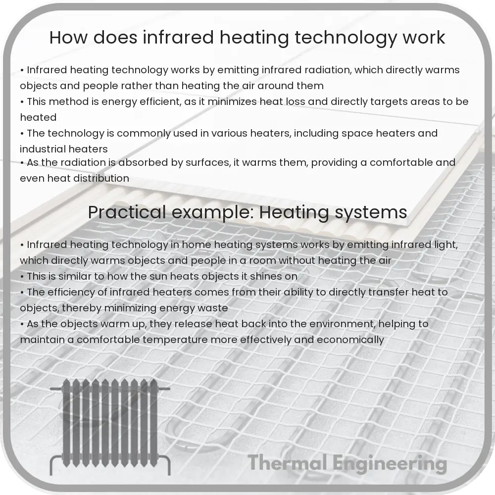
How does infrared heating technology work

Learn the principles of infrared heating technology, its operation, types, and advantages for efficient and comfortable space warming.

How does infrared heating technology work

Understanding Infrared Heating Technology

Infrared heating technology, a form of radiant heat, has become increasingly popular in both residential and commercial settings. This article explores how infrared heaters operate, their efficiency, and their benefits over traditional heating methods.

What is Infrared Heating?

Infrared heating systems emit infrared radiation, which is a type of electromagnetic radiation below the visible spectrum of light. Unlike conventional heating systems that heat the air, infrared heaters directly warm objects, surfaces, and people within their path.

Components of Infrared Heaters

  • Infrared Emitter: The core component is the infrared emitter or lamp, which generates the heat.
  • Reflective Surface: To direct the infrared rays effectively, heaters are often equipped with a reflective surface that focuses radiation outward toward the area to be heated.
  • Heat Exchanger: Some sophisticated models include heat exchangers to enhance heat output via convection, though this is not the primary heating method.

How Does It Work?

When turned on, the infrared heater’s emitter is energized, producing infrared light. This radiation travels at the speed of light until it reaches and is absorbed by objects in the room—such as furniture, floors, and human skin—which convert the radiation into heat. This heat is then slowly released into the environment, warming the surrounding area.

The efficiency of infrared heaters is due to the direct nature of their heat transfer. Unlike conventional heaters that first heat the air (which then transfers heat to objects), infrared heaters warm objects directly, minimizing energy loss.

Types of Infrared Heaters

  • Near Infrared (Short-Wave) Heaters: Emit intense infrared heat, ideal for outdoor spaces and industrial applications.
  • Medium-Wave Heaters: Commonly used in commercial spaces, providing a balance between intensity and comfort.
  • Far Infrared (Long-Wave) Heaters: The gentlest form, perfect for residential indoor heating, as they offer deep warmth without the intense sensation of heat.

Advantages of Infrared Heating Technology

  • Energy Efficiency: As mentioned, the direct heating method means minimal heat is wasted, making this an efficient choice.
  • Health Benefits: Infrared radiation does not circulate dust or allergens in the air, contributing to better indoor air quality.
  • Quick Heat Up: Offers immediate warmth, reaching full operating temperature within seconds to minutes.
  • Directional Heating: Allows targeting specific zones or areas within a space, enhancing comfort and efficiency.
  • Quiet Operation: Operate silently as they do not rely on blowing air through ducts or vents.
  • Environmentally Friendly: Typically have lower carbon emissions compared to conventional heating systems, particularly if powered by renewable energy sources.

Conclusion

Infrared heating technology offers a unique and efficient method of warming spaces by directly heating objects rather than the air. It combines efficiency with environmental benefits, making it an attractive option for sustainable and comfortable indoor environment management. Whether for your home, office, or industrial space, infrared heating provides a smart, modern solution to heating needs.

How does an atmospheric water generator extract water

Learn how Atmospheric Water Generators (AWGs) provide sustainable water by extracting moisture from air, detailing their functionality, efficiency, and applications.

How does an atmospheric water generator extract water

Understanding Atmospheric Water Generators

Atmospheric water generators (AWGs) are devices that extract water from humid ambient air. Water vapor in the air is converted into liquid water through condensation, providing a sustainable source of water for various applications. This technology is particularly useful in areas where water is scarce but air humidity is relatively high.

How Does an Atmospheric Water Generator Work?

The basic principle behind an AWG is simple: it simulates the natural dew point, allowing water to condense and be collected. The detailed process can be broken down into several key steps:

  1. Air Intake: Ambient air is drawn into the AWG by a fan. Air must contain a certain level of humidity to be viable, typically above 30% to effectively produce water.
  2. Cooling and Condensation: The humid air is passed over a cold surface, often cooled by a refrigerant or cooling coils. As the air temperature drops below its dew point, moisture in the air condenses into droplets on the cold surface.
  3. Water Collection: The water droplets grow and eventually drip into a collection tank. Some models use gravity, while others aid the movement with mechanical pumps.
  4. Filtration and Purification: Collected water is often passed through filters to remove impurities and microorganisms. Methods such as ultraviolet light, carbon filters, or reverse osmosis can be employed to ensure the water is safe for drinking.
  5. Storage: The purified water is stored in a sterile tank until it is ready to be used. Some AWGs are integrated with water dispensers for immediate consumption.

Factors Influencing Efficiency

The efficiency of an AWG depends on several environmental and operational parameters:

  • Humidity: Higher humidity levels directly influence the amount of water that can be harvested. AWGs are more effective in humid environments.
  • Temperature: The temperature affects how efficiently the AWG can cool the air to its dew point. Cooler ambient temperatures are generally more conducive to water production.
  • Technology Used: Different cooling technologies and energy sources can impact the efficiency and cost-effectiveness of the device.
  • Maintenance: Regular maintenance, such as cleaning the coils and replacing the filters, is necessary to keep the AWG running effectively.

Applications of Atmospheric Water Generators

AWGs have diverse applications, crucial in both everyday and critical scenarios:

  • Drinking Water: In areas with limited water resources, AWGs provide a vital source of potable water.
  • Agriculture: Water generated can be used for irrigation in controlled agricultural settings, especially in arid regions.
  • Industrial: Industries that require a constant, clean water supply use AWGs to mitigate the risks of water scarcity.
  • Emergency Relief: AWGs can be deployed in disaster-stricken areas to provide immediate access to clean water, essential for survival in the aftermath of catastrophes like earthquakes and hurricanes.

Atmospheric water generators present a promising solution to water scarcity challenges across the globe. As technology advances, the efficiency of these devices continues to improve, making them a viable option for sustainable water sourcing in both developed and developing regions.

How does a cavitation pump move fluids

Learn how cavitation pumps utilize the principles of cavitation to efficiently move fluids in applications like chemical processing and wastewater treatment.

How does a cavitation pump move fluids

Understanding How a Cavitation Pump Moves Fluids

Cavitation pumps, also known as hydrodynamic pumps, operate on the principles of cavitation, a phenomenon in which rapid changes in the pressure of a liquid lead to the formation and collapse of tiny vapor bubbles. These pumps are particularly notable for their ability to move fluids with high efficiency and minimal physical contact, reducing wear and tear. Here, we’ll explore the basic operations and principles behind cavitation pumps.

What is Cavitation?

Cavitation occurs when the pressure in a liquid suddenly drops below its vapor pressure leading to the formation of small gas bubbles (vapor pockets). These bubbles then collapse or implode when they move into areas of higher pressure. This process can generate significant force, which cavitation pumps harness to move fluids.

The Mechanics of a Cavitation Pump

The basic components of a cavitation pump include an impeller, a pump casing, and a suction and discharge section. The impeller, driven by a motor, rotates at high speeds, creating low-pressure areas due to centrifugal force. Here’s how they work:

  1. Initiation of Low Pressure: As the impeller of the pump rotates, it pulls the fluid into the pump casing and accelerated outward. The rapid movement and the design of the impeller blades decrease the pressure around the fluid.
  2. Formation of Vapor Bubbles: When the pressure around the fluid drops below its vapor pressure, vapor bubbles start to form within the fluid. This formation is primarily observed near the eye of the impeller where the pressure reaches its lowest.
  3. Collapse of Bubbles: As the fluid, along with the vapor bubbles, moves towards the outer edges of the impeller and further through the pump’s casing, it encounters higher pressures. The increased pressure causes these bubbles to collapse or implode, releasing energy.
  4. Transfer of Energy: The collapse of these vapor bubbles generates jets of fluid and shock waves, which contribute to the fluid’s momentum. This momentum transfer effectively propels the fluid through the discharge section of the pump, allowing it to move to its intended destination.

Applications and Advantages of Cavitation Pumps

Cavitation pumps are utilized in various applications where gentle handling of the pump contents is necessary. They are particularly used in industries like:

  • Chemical processing
  • Food production
  • Wastewater treatment
  • Pharmaceuticals

The primary advantages of using cavitation pumps include:

  • Reduced Physical Contact: Since the movement and pressures are created by the collapse of vapor bubbles, there’s minimal contact between the pump mechanisms and the fluid, which reduces wear and tear.
  • Low Maintenance: Fewer moving parts and reduced contact result in lower maintenance needs and longer service life.
  • Efficiency: Cavitation pumps are capable of moving viscous fluids with high efficiency compared to traditional pumps.

Conclusion

Cavitation pumps represent a fascinating application of fluid dynamics and the phenomenon of cavitation. By using the natural properties of fluids under changing pressures, these pumps are able to move liquids in an efficient and effective manner, which makes them invaluable in many industrial applications. Understanding the principles behind cavitation pumps not only highlights the innovative uses of physics in engineering but also showcases how advanced engineering solutions can meet real-world challenges.

How does a fluid actuator convert energy

Learn the principles of fluid actuators in hydraulic and pneumatic systems, their energy conversion process, and diverse applications in engineering.

How does a fluid actuator convert energy

Understanding How a Fluid Actuator Converts Energy

Fluid actuators, commonly found in hydraulic and pneumatic systems, are crucial components used to convert energy into mechanical motion. These devices leverage the properties of fluids—liquids and gases—to perform work in various applications, from heavy machinery to robotics. This article explains the fundamental principles behind fluid actuators and how they efficiently convert energy into usable mechanical force.

Types of Fluid Actuators

There are primarily two types of fluid actuators:

  • Hydraulic Actuators: These actuators use liquids, usually oil, as the fluid medium.
  • Pneumatic Actuators: These actuators use gases, typically air, as the fluid medium.

Despite their different mediums, both types of actuators operate on similar principles of fluid dynamics and energy conversion.

Energy Conversion in Fluid Actuators

The process of energy conversion in fluid actuators involves several key steps:

  1. Energy Input: A fluid actuator receives energy typically from an electric or mechanical source which powers a pump. This pump pressurizes the fluid.
  2. Fluid Compression: In the case of hydraulic systems, the liquid is almost incompressible, hence the pump must generate sufficient pressure to move the liquid and create force. For pneumatic systems, air can be compressed, allowing it to store energy in compressed form.
  3. Transmission of Force: The pressurized fluid is then directed through valves and hoses to the actuator cylinder. The amount and direction of fluid flow are controlled to manage the motion of the actuator.
  4. Conversion to Mechanical Motion: The high-pressure fluid enters the cylinder and pushes against a piston. As the piston moves, it converts the pressure from the fluid into a force exerted along the length of the cylinder.
  5. Output Mechanical Work: The linear or rotary motion of the piston can be harnessed to perform various tasks, from lifting heavy loads to precise positioning in industrial automation.

The basic equation that describes the force (F) generated by a fluid actuator is given by:

F = P * A

Where:

  • P is the fluid pressure,
  • A is the cross-sectional area of the piston.

This relationship shows that the force exerted by an actuator is directly proportional to both the pressure of the fluid and the area of the piston it acts upon.

Applications of Fluid Actuators

Due to their robustness and high force output, fluid actuators are extensively used in a variety of fields:

  • Manufacturing: Automation of assembly lines and heavy lifting operations.
  • Construction: Machinery such as excavators and bulldozers rely on hydraulic actuators for movement and operation.
  • Aerospace: Control surfaces on aircraft, such as flaps and slats, are often maneuvered using hydraulic actuators.
  • Robotics: Providing motion and force control in robotic arms and end-effectors.

Fluid actuators, both hydraulic and pneumatic, are indispensable in modern engineering, offering precise control of forces and motion. By understanding how these devices convert and manage energy, engineers can design systems that are both powerful and efficient, meeting the evolving demands of various industries.

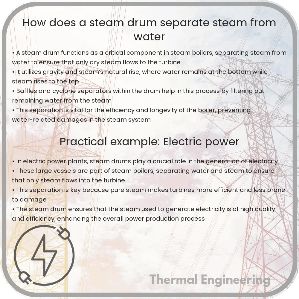
How does a steam drum separate steam from water

Dive into the essentials of steam drums in boilers, exploring their purpose in steam-water separation and their impact on efficiency and safety.

How does a steam drum separate steam from water

Understanding the Role of a Steam Drum in Steam Separation

Steam drums are a critical component of steam boilers, which are widely used in power plants, factories, and ships. Their primary function is to separate steam from water. This process is essential not only to deliver steam at a desired pressure and temperature but also to ensure the efficiency and safety of the boiler system.

What is a Steam Drum?

A steam drum is a standard piece of equipment in water-tube boilers. It is a reservoir of water and steam at the top of the boiler. The steam drum stores the steam generated in the water tubes and acts as a phase-separator for the steam/water mixture.

How the Separation Process Works

The process of separating steam from water in a steam drum involves several physical phenomena and is facilitated by different internal components:

  1. Saturation of Steam: When boiling water generates steam, it rises due to its lower density compared to water.
  2. Momentum and Gravity Separation: As the mixture of water and steam enters the steam drum, the larger water droplets tend to fall to the bottom of the drum due to gravity, while steam rises to the top.
  3. Baffles and Screens: These are installed inside the drum to help separate water droplets from the steam. Baffles change the direction of steam flow and scrub out water droplets. Screens capture and collect droplets.
  4. Centrifugal Separators: In more advanced setups, centrifugal forces are utilized to enhance separation, spinning the mixture and intensively separating the denser water from steam.

Once separation is achieved, steam is drawn from the top of the drum for use in various processes while water remains in the drum to be cycled back through the boiler.

Importance of Efficient Steam-Water Separation

The efficiency of steam-water separation in steam drums is crucial for a number of reasons:

  • Purity of Steam: Higher purity in steam helps prevent corrosion and scaling in steam turbines and other equipment.
  • Energy Efficiency: Proper separation ensures that only steam (and not water) enters the steam line, which enhances thermal efficiency and reduces fuel costs.
  • Operational Safety: Avoiding water carryover into the steam line minimizes the risk of damage caused by water hammer and other hydraulic impacts.

Conclusion

The separation of steam from water within a steam drum is fundamental to the operation of steam generation systems. By utilizing natural physical properties and engineered controls and components inside the drum, efficient and effective separation can be achieved to maintain system efficiency, prolong equipment lifespan, and ensure operational safety. Understanding these mechanisms helps professionals in the engineering field to optimize boiler operations and maintenance.

This insight into steam drum functions serves as a fundamental explanation beneficial for students, engineers, and anyone interested in the operational dynamics of steam boilers.

How does a turboexpander generate electricity

Learn about turboexpanders and their role in converting high-pressure gas into electricity through mechanical energy in industrial processes.

How does a turboexpander generate electricity

Understanding How a Turboexpander Generates Electricity

Turboexpanders, also known as expansion turbines, are devices that harness the energy from a high-pressure gas that expands to a lower pressure and convert it into mechanical energy, which is then often converted to electrical energy. This process is not only fascinating but also pivotal in various industrial applications, particularly in natural gas processing and in the cryogenic industry. Understanding how a turboexpander works to generate electricity involves a basic knowledge of thermodynamics and mechanical engineering principles.

The Basic Components of a Turboexpander

To begin, let’s explore the main components of a turboexpander:

  • Expander: This is the core component where the expansion of gas occurs, leading to the production of mechanical energy.
  • Generator or Alternator: Connected to the expander, this component converts the mechanical energy into electrical energy.
  • Compressor: Often connected via the same shaft, a compressor in some designs uses part of the mechanical energy produced by the expander to compress gases, which are part of another process cycle.

How Does a Turboexpander Work?

The process of generating electricity through a turboexpander can be broken down into several key stages:

  1. Gas Entry: High-pressure gas enters the turboexpander. The gas could be natural gas, air, or any other gas used in industrial processes.
  2. Gas Expansion: As the gas enters the turbine section of the expander, it expands due to the lower pressure inside the turbine chamber compared to the entering pressure. This expansion causes the temperature and pressure of the gas to drop significantly, and the gas accelerates through the turbine blades.
  3. Energy Transfer: The kinetic energy from the accelerated gas is transferred to the turbine blades, causing them to rotate. This rotation converts the kinetic energy of the gas into mechanical energy.
  4. Electricity Generation: The shaft connected to the turbine blades is also connected to an electric generator or alternator. As the shaft rotates, it drives the generator, converting the mechanical energy into electrical energy through electromagnetic induction.

Energy Efficiency and Applications

Turboexpanders are highly efficient, often integrating energy recovery systems that help in improving the overall efficiency of the process in which they are used. For example, in natural gas processing plants, the cold energy produced from the expansion of the gas is used for natural gas liquefaction, which increases the efficiency of the plant.

Another common application of turboexpanders is in geothermal power plants, where hot pressurized steam from within Earth’s surface is expanded to generate electricity. By harnessing energy from natural sources and waste gases, turboexpanders contribute significantly to sustainable energy initiatives.

Conclusion

The integration of a turboexpander in various industrial processes not only aids in efficient energy use but also underscores the versatility of engineering innovations in enhancing sustainable practices. Understanding the workings of such technologies provides insight into the potential of mechanical engineering to revolutionize energy production and management.

Whether it’s processing natural gas or tapping into geothermal energy, the role of turboexpanders in electricity generation is a prime example of engineering efficiency and innovation, showcasing how fundamental physics principles are applied to solve real-world energy challenges.

How does an air bearing support loads

Learn about air bearings and their role in providing frictionless load support through air film lubrication in precision engineering applications.

How does an air bearing support loads

Understanding How Air Bearings Support Loads

Air bearings present a fascinating application of physics in engineering, offering a frictionless contact by using a thin film of air to support and isolate loads. Widely used in precision machinery and high-speed applications, understanding how air bearings function involves exploring the principles of air film formation and load capacity. Here, we’ll break down the mechanism by which air bearings support loads and examine their advantages in various engineering applications.

Principle of Operation

Air bearings operate based on the principle of fluid film lubrication. In this scenario, the air acts as the lubricant. There are two primary types of air bearings: aerostatic and aerodynamic. Aerostatic bearings rely on an external pressurized air source that pushes air through small holes or slots in the bearing surface, creating an air cushion. In contrast, aerodynamic bearings generate air pressure through relative motion between the bearing surfaces and the load itself.

How Air Bearings Support Loads

The load-bearing capacity of air bearings is mainly dependent on the air film formed between the bearing and the moving surface. Here’s how it works:

  • Pressure Buildup: As air is pumped into an aerostatic bearing, or as motion initiates in an aerodynamic bearing, air is trapped and compressed in the narrowing space between the surfaces, creating a pressure buildup.
  • Film Formation: This pressure causes the bearing surface to lift slightly, generating a thin film of air that separates the moving parts This air gap typically measures in micrometers, often less than 50 micrometers.
  • Load Support: The pressurized air film is able to counteract downward gravitational forces of the load, essentially supporting and stabilizing it above the bearing surface without mechanical contact and minimizing friction and wear.

The thickness of the air film is crucial and must be finely controlled to maintain stability. Too thick of an air film can lead to increased vibration and instability, while too thin can result in higher friction and wear.

Mathematical Description

To quantify the load-bearing capacity, we can use simplified equations. The pressure \( P \) generated by the air film and the area \( A \) over which this pressure acts determine the load \( F \) the air bearing can support:

\[ F = P \times A \]

Where:

  • \( P \) is the air pressure in the gap.
  • \( A \) is the effective area of the bearing.

For a more detailed analysis, considerations of air viscosity, speed of operation, bearing geometry, and ambient conditions also factor into the equations. The exact characteristics can be analyzed using numerical methods and dedicated software to simulate airflow and pressure distributions.

Applications of Air Bearings

Air bearings find applications in various fields where low friction, high precision, and minimal wear are crucial:

  • Precision Machine Tools: Used in machining operations that require high accuracy and smooth motion.
  • Coordinate Measuring Machines: Enhances the accuracy of measurements by reducing mechanical resistance.
  • High-Speed Spindles: Used in CNC machines to ensure smooth and accurate machining at high speeds.
  • Clean Room Applications: The lack of lubricants or contaminants makes air bearings ideal for cleanroom environments.

Conclusion

Air bearings exemplify an elegant application of engineering principles to solve real-world problems of load support and friction reduction. By understanding the mechanisms through which they operate and their practical implementations, engineers continue to expand their applications, pushing the boundaries of what can be achieved in precision in mechanical designs and manufacturing processes.

How does a rotary screw air compressor work

Delve into the workings of rotary screw air compressors: An efficient, durable solution for industrial compressed air needs.

How does a rotary screw air compressor work

Understanding Rotary Screw Air Compressors

One of the most widely used types of compressors in industrial applications is the rotary screw air compressor. Known for its efficiency and reliability, this compressor plays a pivotal role in providing compressed air for various uses, from powering pneumatic tools to use in large-scale manufacturing processes. But how exactly does a rotary screw air compressor work? Let’s dive into the mechanics and principles behind this powerful device.

The Basic Components

A rotary screw air compressor mainly consists of two helical screws, known as rotors, which are the heart of the compressor. These rotors are housed within a chamber and are responsible for trapping air and compressing it. Other critical components include:

  • The intake valve: where air enters the compressor.
  • The discharge port: where compressed air exits.
  • The oil separator: to remove oil from the compressed air (in oil-injected models).
  • The motor: which drives the rotors to rotate and compress the air.

Principle of Operation

The operation of a rotary screw air compressor is relatively straightforward yet highly efficient:

  1. Air Intake: The process begins when air is drawn into the compressor through the intake valve.
  2. Compression: As the air enters, it is captured in the cavities between the two rotors. As the rotors turn, these cavities move along the length of the rotors and decrease in volume due to the helical shape of the screws. This movement compresses the air progressively as it moves through the rotor chamber.
  3. Oil Injection (if applicable): In oil-injected rotary screw compressors, oil is sprayed into the compression chamber to cool, lubricate, and seal the compressed air. The oil helps to reduce the temperature during compression, which can significantly improve the efficiency and longevity of the compressor.
  4. Discharge: As the compressed air reaches the end of the screws, it passes through the discharge port. If oil was used, it is separated from the compressed air in the oil separator tank, allowing for clean, pressurized air to be delivered through the system.

Advantages of Rotary Screw Compressors

Rotary screw air compressors are favored for multiple reasons:

  • Continuous Operation: Capable of running 24/7 without a break, which is great for industries that need a constant supply of compressed air.
  • Durability: These compressors are designed to withstand rigorous and continuous use, making them ideal for heavy industrial environments.
  • Efficiency: They provide high volumes of compressed air efficiently, with less energy loss compared to other types of compressors.
  • Lower Heat Generation: The design and oil injection (in oil-injected models) help manage and reduce heat generation, lessening the stress on the compressor’s parts.

Conclusion

The rotary screw air compressor is a sophisticated machine designed to offer reliable and efficient performance for various industrial applications. Understanding how these compressors work not only helps in choosing the right compressor for your needs but also enhances the ability to maintain and troubleshoot them effectively. With their powerful performance and durability, rotary screw compressors continue to be an essential component in industries worldwide.

Thermal effects in photovoltaic systems

Learn how temperature impacts photovoltaic system efficiency, the consequences of thermal effects on solar panels, and strategies to improve their performance.

Thermal effects in photovoltaic systems

Understanding Thermal Effects in Photovoltaic Systems

Photovoltaic (PV) systems, which convert sunlight into electricity, are a cornerstone of sustainable energy. But, like any other electrical system, they are affected by their operating environment—particularly temperature. In this article, we’ll explore how thermal effects impact the efficiency and longevity of photovoltaic systems, and what can be done to mitigate these effects.

How Temperature Affects PV Efficiency

Solar panels are rated based on their performance at standard test conditions (STC), which include a temperature of 25°C. However, actual operating conditions often exceed this temperature, leading to a decrease in efficiency. The performance of a solar cell is inversely related to its operating temperature: as the temperature rises, the efficiency generally falls.

  • Semiconductor Properties: Most photovoltaic cells are made from silicon, a semiconductor whose electrical properties change with temperature. As temperature increases, the band gap of silicon decreases, leading to fewer electrons being able to jump the energy gap to produce electricity.
  • Voltage Drop: Higher temperatures cause a reduction in the open-circuit voltage in solar cells. This is due to an increase in the intrinsic carrier concentration in silicon, which increases the rate of recombination of charge carriers (electrons and holes).

The decrease in performance is often quantified as the temperature coefficient, typically expressed in percentage per degree Celsius (%/°C). For silicon PV cells, the average temperature coefficient for power output is around -0.4%/°C. This means for each degree above 25°C, the efficiency of the panel may decrease by 0.4%.

Long-Term Effects of High Temperature

Continuously operating at high temperatures can also lead to accelerated aging of photovoltaic modules. This can manifest in several ways:

  • Thermal Cycling: Daily temperature variations can cause components within the panel to expand and contract, leading to mechanical stresses that can eventually cause physical damage such as cell cracking or solder bond failures.
  • Delamination and Discoloration: Prolonged exposure to heat can cause the encapsulant materials—used to protect cell circuits—to degrade, leading to delamination and discoloration. This not only reduces the aesthetic value of the solar panels but can also diminish their performance and lifespan.

Mitigating Thermal Effects

To ensure maximum efficiency and longevity of PV systems, several strategies can be employed:

  • Proper Installation: Ensuring sufficient ventilation around PV panels can help dissipate heat more effectively. Panels should be installed with a gap between the roof and the panel, allowing for air circulation.
  • Choosing the Right Materials: Some newer photovoltaic materials and technologies have lower temperature coefficients than standard silicon cells. For example, thin-film solar cells, although less efficient at room temperature, often perform better at higher temperatures relative to silicon PV cells.
  • Thermal Buffering Materials: Using materials that can absorb and reradiate heat can help manage the temperature of the solar cells throughout the day.

In conclusion, while thermal effects pose significant challenges to the efficiency and durability of photovoltaic systems, understanding these influences and implementing effective mitigation strategies can greatly enhance both the performance and lifespan of solar power installations.