Facebook Instagram Youtube Twitter

How does a solar updraft tower generate power

Learn about solar updraft towers, an innovative renewable energy technology that combines solar and wind power to generate electricity efficiently.

How does a solar updraft tower generate power

Understanding the Energy Conversion in Solar Updraft Towers

Solar updraft towers (also known as solar chimneys) are a type of renewable energy technology that leverage both solar power and wind power to generate electricity. Simple yet effective, this technology is an intriguing testament to sustainable engineering principles. Let’s dive into how a solar updraft tower works and explores its potential in the field of green energy.

The Components of a Solar Updraft Tower

A solar updraft tower primarily consists of three parts:

  1. The Solar Collector: A large area of glass or plastic that acts as a greenhouse. This collector is built around the base of a central tower, capturing solar radiation and heating the air underneath.
  2. The Tower: Rising from the center of the collector, the tower acts as a chimney. Typically constructed from concrete or another material with strong thermal stability, the tower allows hot air to rise through it.
  3. Turbines: Positioned at the base of the tower, turbines are installed in openings where the tower meets the collector. As hot air rises through the tower, it passes through these turbines, generating electricity.

How It Generates Power

The operational principle of a solar updraft tower is grounded in the basic physics of heat and flow dynamics. Here’s the step-by-step process:

  • Solar Heating: The sun’s rays heat the air beneath the collector canopy, significantly increasing its temperature. Because warm air is less dense than cooler air, it begins to rise.
  • Updraft Creation: As the hot air is confined under the collector, it seeks a way to escape and naturally flows toward the tower, which provides a route to higher altitudes. The structural design of the tower promotes a strong upward draft.
  • Energy Conversion: The rapidly rising warm air passes through turbines at the base of the tower. As the air pushes through the turbine blades, it causes them to spin, driving the turbine generators to produce electricity.
  • Continuous Operation: As long as sunlight heats the air under the collector, and as long as the architecture supports the flow of air, the cycle continues, allowing for continuous power generation during sunlight hours.

Advantages and Limitations

Solar updraft towers offer several advantages:

  • Renewable and Clean: They utilize solar energy, which is abundant and clean.
  • Low Operating Costs: Once built, the operational and maintenance costs are relatively low compared to other power generation methods.
  • Long Lifespan: Structures are generally robust and can last many years with proper maintenance.

However, there are some limitations:

  • Large Land Area: A significant amount of land is required to accommodate the collector area.
  • Initial Investment: The initial construction costs can be quite high due to the size of the structures needed.
  • Efficiency: The overall efficiency of converting solar energy into electricity is lower compared to other technologies like photovoltaic cells.

The Future of Solar Updraft Towers

The potential for solar updraft towers in contributing to the renewable energy mix is significant, especially in sunny, arid regions where solar radiation is high and land may be less valuable. While not as widespread as solar panels or wind turbines, the unique benefits of solar updraft towers, particularly for areas with specific geographical and climatical advantages, keep them in consideration for future renewable energy projects.

By harnessing the simple physics of air movement and solar heating, solar updraft towers offer an intriguing option for sustainable power generation, showcasing how innovative engineering can convert natural processes into usable energy.
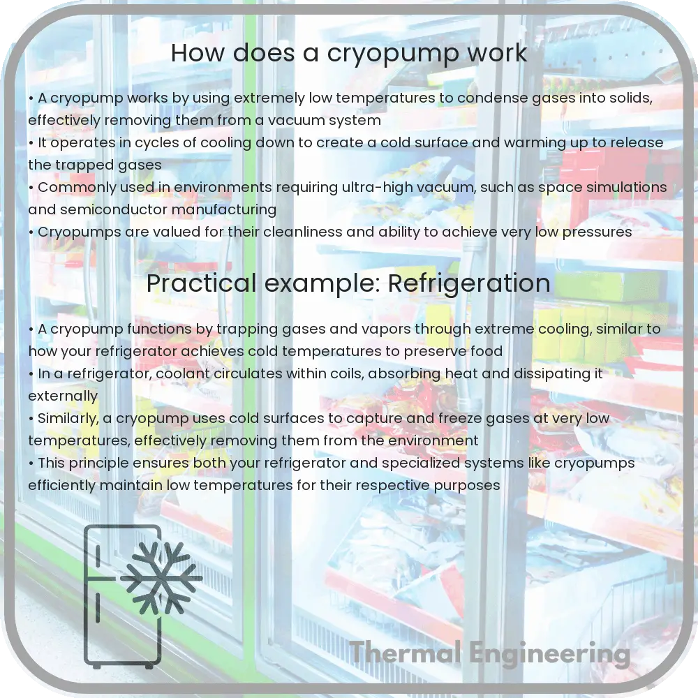
How does a cryopump work

Learn how cryopumps create ultra-high vacuums using cryogenic technology for scientific and industrial applications.

How does a cryopump work

Understanding the Mechanics of a Cryopump

A cryopump is an essential tool in various scientific and industrial fields, utilized chiefly for creating ultra-high vacuum environments. This device operates on the principles of cryogenic technology, using extremely low temperatures to condense gases from the environment, thus effectively removing them to create a vacuum. Let’s dive into the workings and applications of a cryopump.

Principle of Operation

The basic operational principle of a cryopump is quite simple. It uses a cold surface, usually cooled by liquid helium or nitrogen, to freeze and trap gas molecules that are inside a vacuum chamber. The colder the surface, the more effective it is at condensing and trapping these molecules.

  • Cooling System: The heart of the cryopump is its cooling system, which can reach temperatures as low as 10 K (-263.15°C) using helium and up to 77 K (-196°C) with nitrogen. These temperatures are crucial for the effectiveness of the pump.
  • Adsorption: When gas molecules come into contact with the cold surface of the cryopump, they lose their kinetic energy rapidly and adhere to the surface in a process known as adsorption.
  • Condensation: At the same time, other gases that are less prone to adsorption condense into a solid or liquid at these low temperatures.
  • Exhaust Mechanism: Once the surface is saturated with gas molecules, the cryopump needs to be regenerated. This involves warming the surface to release the trapped gases, which are then expelled from the system.

Types of Cryopump

There are mainly two types of cryopumps:

  1. Bath Cryopumps: These rely on a bath of cryogenic fluid to cool a thermal shield and cold surfaces within the pump. They are generally more robust and suitable for continuous operation.
  2. Refrigerated Cryopumps: Utilizing a closed-cycle refrigerator, these pumps cool the surfaces directly. They are more complex but offer ease in temperature control and regeneration processes.

Applications of Cryopumps

Cryopumps are widely used in several fields due to their ability to achieve and maintain a high vacuum. Common applications include:

  • Semiconductor Manufacturing: Cryopumps provide the clean, ultra-high vacuum environment necessary for the production of semiconductors.
  • Space Simulation Chambers: Mimicking the vacuum of space requires the removal of all air molecules, a task ideally suited for cryopumps.
  • Particle Accelerators: Cryopumps are used to maintain the vacuum needed for the unimpeded travel of particles in accelerators.
  • Freeze Drying: In pharmaceuticals and food preservation, cryopumps are used to extract moisture content under vacuum, enhancing the freeze-drying process.

Advantages and Disadvantages

While cryopumps are beneficial for certain applications, they also come with their own set of advantages and disadvantages.

  • Advantages:
    • High pumping speed for all gases.
    • Creates ultra-high vacuum conditions efficiently.
    • No contamination of the vacuum with pump oils or fluids.
  • Disadvantages:
    • Requires periodic regeneration to release trapped gases.
    • High initial and operating costs due to cryogenic materials and technology.
    • Limited to environments where the introduction of vibration is not a concern (due to the operation of cryogenic compressors).

Overall, the cryopump is a sophisticated device that plays a critical role in applications requiring stringent vacuum conditions. By understanding its operation, types, and uses, engineers and technicians can better harness this technology to suit specific industrial and research needs.

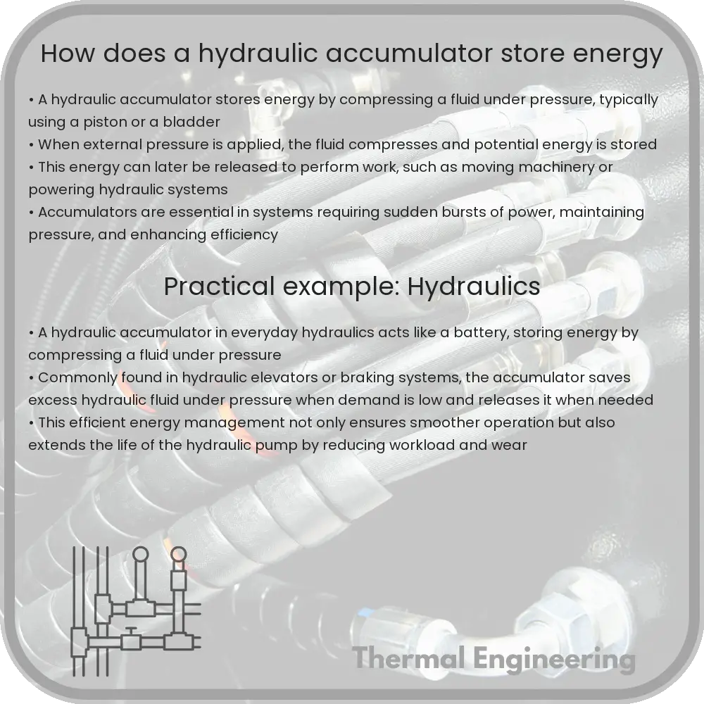
How does a hydraulic accumulator store energy

Learn how hydraulic accumulators store energy, manage pressure, and increase efficiency in hydraulic systems through their innovative design and operation.

How does a hydraulic accumulator store energy

Understanding How a Hydraulic Accumulator Stores Energy

A hydraulic accumulator is a vital component used in hydraulic systems, serving the primary function of storing energy by using a compressible gas (usually nitrogen). This form of energy storage not only enhances the efficiency of the hydraulic system but also provides essential functions such as shock absorption, maintaining pressure, and compensating for leaks. In this article, we will explore the mechanics of how a hydraulic accumulator stores energy and the principles behind its operation.

Components and Types of Hydraulic Accumulators

Before diving into the energy storage process, it’s important to understand the basic components of a hydraulic accumulator. Typically, it consists of a cylindrical chamber which is divided into two parts: one side filled with hydraulic fluid and the other with gas (usually nitrogen). The two most common types of accumulators are:

  • Bladder Type: Involves a rubber bladder that separates the gas from the hydraulic fluid.
  • Piston Type: Uses a piston as a moveable barrier to separate the fluid from the gas.

Each type of accumulator works under the same basic principle but may have different applications and efficiency based on the specific requirements of the hydraulic system.

The Physics of Energy Storage

The fundamental principle behind a hydraulic accumulator is the conversion of potential energy into kinetic energy and vice versa. Here’s how the process works in steps:

  1. Charging the Accumulator: When hydraulic fluid enters the accumulator, it pushes the piston or compresses the bladder, which in turn compresses the gas in the gas chamber.
  2. Energy Storage: The compression of the gas stores potential energy in the accumulator. The amount of energy stored is dependent on the pressure and volume of the gas according to the relation E = (1/2) * P * V, where E is energy, P is pressure, and V is volume.
  3. Energy Release: When the hydraulic system requires energy, the compressed gas expands, pushing the hydraulic fluid back into the system and thus converting the stored potential energy back into kinetic energy.

This cycle allows the hydraulic accumulator not just to store energy, but also to act as a shock absorber, dampening any pulses that occur from the pumps or external forces, thus protecting the system and ensuring stable operation.

Benefits of Using Hydraulic Accumulators

Beyond just energy storage, hydraulic accumulators provide several benefits to hydraulic systems, including:

  • Improved Efficiency: By storing excess hydraulic energy, accumulators can provide additional power without extra fuel or power consumption, especially during peak load times.
  • Emergency Power Source: In case of power failure, the stored energy in the accumulator can be used to safely shut down the system or maintain system operation until power is restored.
  • Longevity and Maintenance: Accumulators help reduce wear and tear on hydraulic pumps by smoothing out pulsations and spikes in pressure, potentially reducing maintenance costs and extending the lifespan of the system.

Conclusion

The hydraulic accumulator is an ingenious and essential component in modern hydraulic systems. Understanding how it stores energy illuminates not only a key aspect of system efficiency and safety but also highlights the seamless application of basic physical principles in engineering solutions. Whether in industrial machinery, aerospace, automotive systems, or renewable energy technologies, hydraulic accumulators play a critical role in enhancing system performance and reliability.

By appreciating the simple yet effective mechanism of hydraulic accumulators, we get a glimpse into the practical applications of physics in engineering that directly impact various aspects of technology and industry.

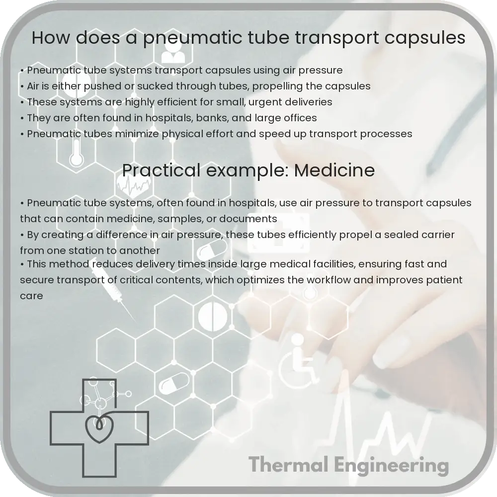
How does a pneumatic tube transport capsules

Learn how pneumatic tube transport systems use air pressure and fluid dynamics to efficiently move capsules in a network of tubes for various applications.

How does a pneumatic tube transport capsules

Understanding Pneumatic Tube Transport Systems

Pneumatic tube transport systems seem like something out of a science fiction novel, but they have been around since the 19th century. These systems use air pressure differences to propel cylindrical containers, known as capsules, through a network of tubes. The basic principles behind pneumatic tubes are similar to those of everyday items such as vacuum cleaners or blowers. Let’s dive into how these fascinating systems work and examine their engineering principles.

Components of a Pneumatic Tube System

The primary components of a pneumatic tube system include:

  • Capsules: Containers that hold items for transport.
  • Tubes: Network of sealed tubes connecting sending and receiving stations.
  • Blower: Generates air pressure to move the capsules.
  • Stations: Points where items are sent and received.
  • Switches: Direct the capsules to their designated destination.

How It Works

The operation of a pneumatic tube system is straightforward yet ingeniously applied:

  1. Insertion: A user places the items into a capsule and inserts it into the station.
  2. Creation of Air Pressure Difference: At the sending station, the system seals the tube and a blower either creates a vacuum (negative pressure) behind the capsule or high pressure in front of it.
  3. Movement of Capsule: The pressure difference across the capsule propels it through the tube towards the destination. Capsules can travel at speeds up to 25 miles per hour (mph), depending on the system design and distance.
  4. Routing: Switches in the network route the capsule to the intended receiving station.
  5. Arrival and Retrieval: Upon reaching its destination, air brakes slow down the capsule, and it is either automatically or manually retrieved from the tube.

Physical Principles Involved

The primary physical principles behind pneumatic tubes involve air pressure, fluid dynamics, and Bernoulli’s principle:

  • Air Pressure: Air pressure is used to create a force on the capsules. When the pressure behind a capsule is higher than in front, the air molecules push the capsule forward. Conversely, if the pressure is lower behind the capsule than in front, it moves towards the lower pressure area.
  • Bernoulli’s Principle: This principle explains that in fluid dynamics, an increase in the speed of the fluid occurs simultaneously with a decrease in pressure or potential energy. In pneumatic tubes, the air acting as the fluid can accelerate the capsules while the air pressure varies.

Applications and Uses

Pneumatic tube systems are not just relics; they are used in various modern applications including:

  • Hospitals: For quick delivery of samples, medications, and documents across different departments.
  • Banks: At drive-thru banks to transport money and documents between customers and tellers.
  • Retail: In large stores, to move cash from registers to a central secure location.
  • Industrial Settings: To send parts or tools within a manufacturing facility.

Pneumatic tube transport systems are a fascinating example of how fundamental physics principles can be harnessed to solve practical problems in innovative ways. By understanding these systems, we get a glimpse into the potential future of transportation and automated delivery systems.

How does a thermal oxidizer destroy pollutants

Learn how thermal oxidizers mitigate industrial pollution by breaking down hazardous emissions into less harmful byproducts using high-temperature oxidation.

How does a thermal oxidizer destroy pollutants

Understanding Thermal Oxidizers: How They Destroy Pollutants

Thermal oxidizers are critical components in managing industrial pollution. They are designed to treat exhaust gases before they are released into the atmosphere, effectively reducing environmental pollution. This article explores how thermal oxidizers operate and how they destroy pollutants, breaking down the complex process into understandable parts.

What is a Thermal Oxidizer?

Also known as a thermal incinerator, a thermal oxidizer is a type of air pollution control equipment used in industrial processes to minimize emissions of hazardous air pollutants (HAPs), volatile organic compounds (VOCs), and odorous emissions. The fundamental principle of a thermal oxidizer is to decompose hazardous gases at a high temperature and release them as less harmful byproducts.

Key Components of a Thermal Oxidizer

  • Combustion Chamber: A high-temperature chamber where the oxidation of VOCs occurs.
  • Heat Exchanger: A device that recovers heat from the combustion gases to preheat the incoming polluted air, thereby saving energy.
  • Burner: Used to initiate and maintain combustion within the chamber.
  • Stack: A chimney through which the treated gases are expelled into the atmosphere.
  • Control System: Monitors and controls the temperature, flow, and combustion to ensure optimal operation and safety.

Principle of Operation

At its core, the thermal oxidizer uses a simple concept: high heat, typically between 760°C to 815°C (1400°F to 1500°F), to initiate a chemical reaction between the organic pollutants in the waste gas stream and oxygen. This reaction is generally represented as:

    Organic Compounds + O2 → CO2 + H2O

The above equation shows that the organic compounds (pollutants) react with oxygen to produce carbon dioxide (CO2) and water (H2O), which are significantly less harmful to the environment.

Steps Involved in Pollutant Destruction

  1. Pre-heating: The polluted air is pre-heated by the heat exchanger before entering the combustion chamber.
  2. Combustion: The pre-heated air mixes with the VOCs and enters the combustion chamber where it is heated to the necessary temperature for oxidation to occur.
  3. Oxidation: At high temperatures, the VOCs chemically react with the oxygen in the air to form carbon dioxide and water.
  4. Energy Recovery: After combustion, the hot gases pass through a heat exchanger where their energy is used to pre-heat incoming streams of polluted air.
  5. Exhaust: Finally, the cleaned air is expelled from the stack into the atmosphere.

Advantages of Using Thermal Oxidizers

  • High Efficiency: Thermal oxidizers can achieve over 99% destruction efficiency for many pollutants.
  • Energy Efficiency: With the aid of heat recovery systems, they can be designed to be energy efficient.
  • Versatility: Capable of handling multiple streams of waste gas and various types of pollutants.
  • Compliance: Helps facilities meet stringent environmental regulations by controlling emissions of hazardous and odorous compounds.

In conclusion, thermal oxidizers are an effective engineering solution for managing and destroying pollutants in industrial emissions. They play a vital role in protecting our environment by converting harmful pollutants into harmless byproducts through the application of high heat and oxidation. Understanding their functionality helps in appreciating the complex technologies involved in pollution control and underscores the importance of environmental management in industrial applications.

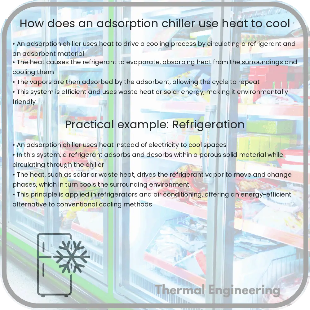
How does an adsorption chiller use heat to cool

Learn how adsorption chillers use heat sources like solar or waste heat to provide eco-friendly and efficient cooling solutions.

How does an adsorption chiller use heat to cool

Understanding Adsorption Chillers: How Heat Can be Used to Cool

The concept of using heat to produce a cooling effect might initially sound counterintuitive, but adsorption chillers leverage this unique process to provide efficient air conditioning and refrigeration without relying heavily on electricity. This process is not only fascinating from a scientific standpoint but also offers significant environmental benefits. Let’s delve into how adsorption chillers work and explore their applications in today’s engineering world.

What is an Adsorption Chiller?

An adsorption chiller is a type of refrigeration system that uses a heat source to generate cooling. Unlike traditional vapor-compression chillers that require mechanical energy to operate compressors, adsorption chillers use thermal energy. This can be sourced from solar heat, waste heat from industrial processes, or even natural gas.

The Basic Components

  • Adsorbent Material: Commonly silica gel or zeolites, which have a high capacity to attract and hold water molecules.
  • Evaporator: Where the refrigerant (typically water) evaporates, pulling heat from the surroundings, thus causing cooling.
  • Condenser: Cools down and condenses the refrigerant vapor back into liquid form.
  • Generator: Where heat is applied to the refrigerant, causing it to vaporize and start the cycle.

How Does It Work?

The operation of an adsorption chiller can be broken down into a few key steps:

  1. Adsorption: At the beginning of the cycle, the adsorbent material is dry and has a high affinity for the refrigerant vapor. As the refrigerant evaporates in the evaporator, it is absorbed by the adsorbent material in what is known as the adsorber.
  2. Generation: Heat is then applied to the adsorber, which causes the refrigerant to desorb (or detach) from the adsorbent material and vaporize. This step requires a heat input, which might come from solar heat, waste heat, or another source.
  3. Condensation: The refrigerant vapor, now at a high pressure due to the heat, travels to the condenser where it releases its heat and changes back into a liquid.
  4. Evaporation: This liquid refrigerant then flows back to the evaporator, where it once again absorbs heat from the surroundings and evaporates, thus reducing the temperature and providing a cooling effect.

After desorption, the cycle repeats, relying primarily on the heat input at the generation phase for continued operation.

Why Use an Adsorption Chiller?

Adsorption chillers offer several distinct advantages:

  • Eco-friendly: They can dramatically lower electricity consumption, primarily when the heat source is waste heat or solar energy. This makes them an attractive option for sustainable building projects and industrial applications.
  • Efficient use of waste heat: Industries that generate a large amount of waste heat can use adsorption chillers to turn this otherwise wasted resource into something valuable—cooling.
  • Low maintenance: With fewer moving parts compared to conventional chillers, adsorption chillers generally have lower maintenance requirements and longer life spans.

Real-World Applications

Adsorption chillers are utilized across various sectors. In industries, they are used to provide comfort cooling or process chilling using waste heat from processes or power generation equipment. In renewable energy projects, they are often paired with solar thermal collectors to cool buildings without using conventional, power-hungry air conditioners. This application can be particularly appealing in remote or off-grid areas where electricity is scarce or expensive.

In conclusion, adsorption chillers exemplify an innovative application of thermodynamic principles to solve practical engineering problems, offering an environmentally friendly and efficient solution for cooling using heat. By understanding and utilizing the adsorption refrigeration cycle, engineers can design systems that enhance energy efficiency and sustainability across a range of applications.

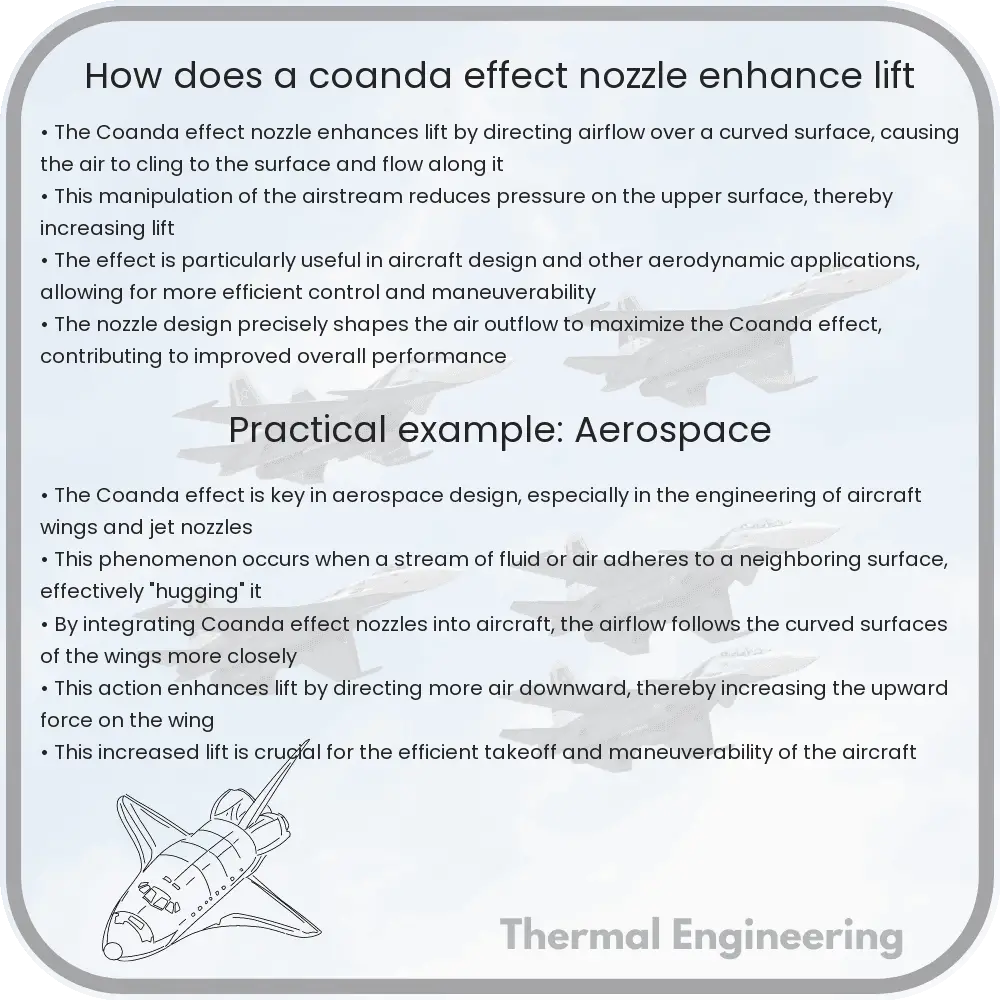
How does a coanda effect nozzle enhance lift

Learn about the Coanda effect nozzle and its role in increasing aircraft lift through fluid dynamics, benefiting maneuverability and efficiency.

How does a coanda effect nozzle enhance lift

Understanding the Coanda Effect Nozzle in Enhancing Lift

The Coanda effect is a fluid dynamics phenomenon utilized ingeniously in various engineering applications, one of which includes enhancing the lift in aircraft. This effect involves the tendency of a stream of fluid (which can be a liquid or a gas) to follow a nearby curved surface, rather than continuing on its initial path. This simple yet powerful principle can have profound implications on lift, particularly when applied through devices like the Coanda effect nozzle in the realm of aerospace engineering.

What is the Coanda Effect?

Named after Romanian inventor Henri Coanda, who first identified the principles behind the behavior of fluid flows, the Coanda effect describes how a jet flow attaches itself to a nearby surface and follows its contour. In practical terms, when air is expelled from a nozzle that is positioned near a curved surface, the air stream adheres to the surface and follows its shape, significantly altering the pathway of the airflow.

How Does the Coanda Effect Nozzle Work?

In an aircraft, Coanda effect nozzles can be used to enhance lift by directing airflow over control surfaces in a way that maximizes the lift force. The mechanism is relatively straightforward:

  1. Air is expelled from a nozzle at high velocity.
  2. The nozzle is designed such that it is close to or part of a curved surface of the aircraft’s structure, often part of the wing or tail.
  3. The high-velocity air adheres to the curved surface due to the Coanda effect, altering the direction of the airflow.
  4. By carefully directing this airflow, the lift generated by the wing can be significantly increased, as the curvature of the surface leads to a change in air pressure.

This redirected airflow can produce additional lift because it interacts with the wing’s surface to change the effective angle of attack and accelerates the air over the wing. Increased velocity over the wing’s surface reduces the pressure according to Bernoulli’s principle (which states that an increase in the speed of a fluid occurs simultaneously with a decrease in pressure) and thus enhances the lift.

Applications and Benefits

  • Increased Maneuverability: Aircraft equipped with Coanda effect nozzles can achieve greater control and maneuverability, particularly useful in military aircraft where rapid changes in direction are crucial.
  • STOL Capabilities: Short Takeoff and Landing (STOL) capabilities are enhanced by Coanda effect nozzles, allowing aircraft to operate from shorter runways, a critical advantage in many civilian and military operations.
  • Fuel Efficiency: By optimizing lift and control, Coanda effect nozzles can contribute to better overall aerodynamic efficiency, which can lead to reduced fuel consumption.

While the Coanda effect is a relatively simple fluid dynamic principle, its applications, such as in Coanda effect nozzles, illustrate the complex and innovative ways physics and engineering intersect to solve real-world challenges and enhance technology in fields such as aerospace. By understanding and leveraging natural phenomena like the Coanda effect, engineers continue to develop solutions that push the boundaries of what is possible in aviation and beyond.

How does a refrigerated air dryer remove moisture

Learn how refrigerated air dryers efficiently remove moisture from compressed air systems to ensure dry air for industrial uses.

How does a refrigerated air dryer remove moisture

Understanding How a Refrigerated Air Dryer Removes Moisture

One common question that arises when discussing compressed air systems is how these systems manage to remove moisture effectively. A critical component often used for this purpose is a refrigerated air dryer. In this article, we explore the principles and mechanisms behind a refrigerated air dryer’s ability to condense and remove moisture from compressed air, ensuring that the air is suitable for various industrial applications.

Working Principle of a Refrigerated Air Dryer

The primary function of a refrigerated air dryer is to cool the compressed air to a temperature where water vapor condenses into liquid water. This process is similar to how moisture condenses on the outside of a cold beverage can. Here’s how the process unfolds:

  1. Air Cooling: Compressed air, heated during the compression process, enters the dryer and is initially cooled by the incoming, outgoing cold air in an air-to-air heat exchanger. This pre-cooling helps in reducing the workload on the system.
  2. Further Chilling: Post pre-cooling, air then passes through the refrigeration system where it’s further cooled to a specified dew point, typically around 2-10 degrees Celsius. The dew point is the temperature at which air can no longer hold water vapor, leading to condensation.
  3. Moisture Separation: Once the air is cooled below its dew point, moisture in the air condenses into liquid droplets which are collected in a separator.
  4. Discharging Moisture: The condensed water is then drained away from the system, while the dry air is reheated in the air-to-air exchanger by the incoming warm, moist air (recuperating the refrigeration energy and warming the outgoing dry air to prevent pipe sweating).

The key to this system’s efficiency lies in its ability to rapidly cool and subsequently warm up the air, thus managing the moisture without significant energy consumption or manual intervention.

Components of a Refrigerated Air Dryer

  • Compressor: Helps to circulate the refrigerant through the cooling system.
  • Condenser: Releases heat removed from the air to the environment.
  • Expansion Valve: Reduces the pressure of the refrigerant, enabling it to expand and cool.
  • Evaporator: Where the compressed air is cooled by the refrigerant.
  • Moisture Separator: Captures and removes liquid moisture from the cold air.
  • Drain: Expels the collected water out of the system.

This collective arrangement not only ensures the effective drying of compressed air but also integrates seamlessly with various industrial systems, requiring minimal maintenance and operational oversight.

Applications and Benefits

Refrigerated air dryers are essential in numerous applications where moisture can compromise the quality or efficiency of processes. Industries like pharmaceuticals, food processing, and manufacturing rely on these dryers to prevent water from interfering with direct production processes or damaging pneumatic equipment.

The main benefits of using a refrigerated air dryer include:

  • Improved System Reliability: Dry air prevents corrosion and minimizes the risk of pneumatic equipment failure.
  • Enhanced Product Quality: Ensures that moisture does not contaminate products, particularly in paint applications or chemical mixes.
  • Energy Efficiency: Modern refrigerated dryers are designed to minimize electricity usage, thereby reducing operational costs.

Understanding how refrigerated air dryers function helps in recognizing their importance and efficiency in industrial applications. By effectively removing moisture from compressed air, these dryers ensure reliability, safety, and quality across various fields, demonstrating a key application of engineering principles in everyday technologies.

How does a savonius wind turbine capture wind

Learn about the Savonius wind turbine, its unique vertical-axis design, how it works, and the advantages and limitations of this wind energy system.

How does a savonius wind turbine capture wind

Understanding the Savonius Wind Turbine

Wind energy is a growing source of renewable energy worldwide. A variety of wind turbine designs are utilized to capture this powerful natural resource, with each design suited to different environmental conditions and energy needs. One of the simplest and most distinctive types of wind turbines is the Savonius wind turbine. In this article, we will explore how the Savonius wind turbine captures wind and converts it into useful energy.

Design and Operation

The Savonius wind turbine, named after Finnish inventor Sigurd Savonius who developed it in the 1920s, is a type of vertical-axis wind turbine. Unlike the more common horizontal-axis wind turbines that resemble windmills, the Savonius turbine’s axis of rotation stands vertical to the ground. This design feature offers some unique advantages such as independence from wind direction and suitability for areas where wind directions are highly variable.

The basic structure of a Savonius turbine consists of two or three scoops. These scoops are usually half-cylinder shapes attached to a vertical shaft. They are designed to capture wind from any direction, with their curved surfaces directing the wind to generate rotational motion.

How It Captures Wind

The mechanics of wind capture by a Savonius turbine can be understood through its unique scoop-like blade design. Here’s how it works:

  • Wind Interaction with Concave and Convex Surfaces: As wind strikes the concave side of one of the scoops, it pushes against this side and transfers its energy to the scoop, creating a driving force. The convex side of the opposite scoop, meanwhile, creates less resistance against the wind and allows the wind to pass more easily. This difference in pressure on the two sides of the turbine creates a torque, or rotational force, causing the shaft to spin.
  • Rotation: The continuous differential pressure due to wind hitting the concave and convex sides of the blades causes the turbine to rotate around its vertical axis. This rotation can then be used to generate electricity or perform mechanical work, such as pumping water.
  • Effect of Wind Speed: The performance of a Savonius turbine is significantly affected by wind speed. Higher wind speeds increase the rotational speed of the turbine, thereby generating more power. However, due to their design, Savonius turbines generally have lower rotational speeds compared to horizontal-axis turbines.

Applications and Limitations

Savonius wind turbines are particularly prized for their simplicity, low operating costs, and ability to operate under varied wind conditions. They are commonly used in urban environments, for small-scale energy generation projects, and in locations where wind directions fluctuate. In addition to electricity generation, they are also used in ventilation and water pumping applications.

However, it is important to note that Savonius turbines are not the most efficient form of wind turbine. They typically convert less than 15% of the wind’s energy into usable mechanical power, whereas other designs such as the Darrieus wind turbine can achieve higher efficiencies.

Conclusion

The Savonius wind turbine offers a unique design and operational simplicity that make it suitable for small-scale and low-cost energy solutions, particularly in challenging wind environments. Understanding how it captures and utilizes wind helps appreciate its role in the diverse world of wind-powered energy systems and highlights the importance of selecting the right turbine type based on specific situational needs.

By exploring different wind turbine designs, such as the Savonius, we can better understand how to harness the power of wind efficiently and innovatively to meet various energy demands around the globe.

How does a screw pump move fluids

Delve into the functionality and advantages of screw pumps, a type of positive displacement pump used across numerous industries for efficient fluid handling.

How does a screw pump move fluids

Understanding the Mechanics of a Screw Pump

A screw pump is a type of positive displacement pump, which means it moves a fluid by repeatedly enclosing a fixed volume and moving it mechanically through the system. The mechanics of a screw pump are fascinating due to their simplicity and efficiency. In this article, we will explore the basic working principle of screw pumps, their design, and common applications.

Working Principle of Screw Pumps

Screw pumps consist of one or more screws (also known as rotors) that, when rotated, move the fluid along the screw’s axis. These pumps are remarkably versatile, able to handle fluids with varying viscosities and containing solids without significant damage. There are typically three key types of screw pumps:

  • Single Screw Pump: Features one helical rotor that moves fluid along its length.
  • Twin Screw Pump: Consists of two intermeshing screws that trap the fluid between them and push it forward.
  • Triple Screw Pump: Uses three screws, where the central rotor drives the other two rotors to move the fluid.

The primary mechanism involves the turning of the screw(s) inside a tightly fitted casing. As the screws rotate, cavities form between the screw threads and the casing, which are progressively filled with fluid. The fluid moves from the suction side of the pump to the discharge side as the screws continue to rotate, moving the fluid along the length of the screws and pushing it forward into the discharge pipe.

Mathematical Insight into Screw Pump Operations

The volume flow rate \( Q \) of a screw pump can be estimated from its geometrical characteristics and the speed of the screw’s rotation. Specifically, the flow rate is influenced by the screw’s radius \( r \), its length \( L \), the number of screws \( n \), and the rotational speed \( \omega \). The flow rate can be approximated using the equation:

\[ Q = n \cdot r^2 \cdot \pi \cdot L \cdot \omega \]

This equation implies that increasing the radius of the screws, the length of contact inside the casing, the number of screws, or the rotational speed can enhance the pump’s flow rate.

Advantages and Applications of Screw Pumps

Screw pumps are highly favored in various industries due to their design advantages, which include:

  • Ability to handle a wide range of fluid viscosities and mixed flows containing gases and solids.
  • Low maintenance requirements due to fewer moving parts.
  • Smooth, consistent flow without pulsations.
  • High efficiency and reliability.

Common applications of screw pumps include:

  • Handling waste and wastewater in municipal engineering.
  • Transferring heavy oils, lubricants, and fuel in the maritime and energy sectors.
  • Food and beverage industries, particularly for transporting viscous fluids like oils and fats.
  • Chemical manufacturing, where precision and reliability in fluid handling are crucial.

In conclusion, screw pumps are a crucial component in various engineering applications, admired for their efficiency and versatility. Their ability to transport different types of fluids smoothly and reliably makes them indispensable in many industries. With a simple yet effective operating principle, screw pumps demonstrate how classical engineering designs continue to play vital roles in modern technology.