Facebook Instagram Youtube Twitter

How radiation affects thermal energy transfer

Learn about radiation’s role in thermal energy transfer, its principles according to Planck’s law and the Stefan-Boltzmann law, and its engineering applications.

How radiation affects thermal energy transfer

Understanding the Impact of Radiation on Thermal Energy Transfer

Thermal energy transfer is an essential concept in engineering, impacting everything from the efficiency of heating systems to the design of thermal insulators. One of the fundamental modes of heat transfer is radiation, which can significantly influence how thermal energy is moved or contained in different environments. In this article, we explore how radiation affects thermal energy transfer and its implications in engineering applications.

What is Radiation?

Radiation is the process by which heat energy is emitted or absorbed by bodies in the form of electromagnetic waves or photons. It is one of the three principal methods of heat transfer, alongside conduction and convection, but it is unique in that it doesn’t require any medium for transfer. This means that radiation can occur through a vacuum, such as the heat transfer from the Sun to the Earth.

How Does Radiation Occur?

Radiation heat transfer occurs through the emission of infrared radiation from the surface of an object. According to Planck’s law of black body radiation, the energy emitted by a body per unit area is directly proportional to the fourth power of its absolute temperature. The Stefan-Boltzmann law mathematically describes this relationship:

E = σT4

where E is the emissive power, σ (the Stefan-Boltzmann constant, approximately 5.67 x 10⁻⁸ W/m2K4) is a constant, and T is the absolute temperature of the body in Kelvin.

Factors Influencing Radiation-Induced Thermal Transfer

  • Surface Properties: The ability of a surface to emit or absorb radiation is quantified by its emissivity (ε), ranging from 0 (perfect reflector) to 1 (perfect emitter). Materials with high emissivity are more effective in radiative heat transfer.
  • Temperature Difference: The greater the temperature difference between two bodies, the greater the radiative heat transfer. This follows from the Stefan-Boltzmann law, where radiative heat transfer increases with higher temperatures.
  • Geometrical Configuration: The shape and relative positioning of surfaces also affect radiative heat exchange. For example, parallel plates with facing surfaces have different radiative interactions compared to staggered placements.
  • Wavelength of Radiation: Different materials absorb and emit radiation differently at various wavelengths. This spectral dependency is crucial in designing systems like solar panels or thermal insulators.

Engineering Applications

The principles of radiative heat transfer are crucial in many engineering disciplines. Some key applications include:

  • Thermal Insulation: Materials used in insulation are designed with low emissivity to reduce heat loss through radiation, improving energy efficiency in buildings and vehicles.
  • Solar Energy: The design of solar panels considers radiation absorption. Materials with high absorptivity at the solar wavelengths maximize energy capture.
  • Cooling Systems: Radiative cooling systems exploit the night sky’s thermal radiation to dispense heat, functioning as an eco-friendly cooling solution.
  • Spacecraft Thermal Control: In the vacuum of space, where conduction and convection are negligible, radiative heat transfer becomes the dominant thermal management mechanism.

Conclusion

Understanding how radiation affects thermal energy transfer equips engineers with the knowledge to design more efficient systems in fields ranging from aerospace to residential heating. By manipulating factors such as emissivity and optimizing geometrical configurations, engineers can control and optimize heat transfer for various applications, demonstrating the profound impact of radiation in thermal engineering.

How does a bimetallic strip work in thermostats

Learn about bimetallic strips, their role in thermostat function, and their reliance on differential thermal expansion for temperature control.

How does a bimetallic strip work in thermostats

Understanding the Function of Bimetallic Strips in Thermostats

A bimetallic strip is a simple yet ingenious component used in many mechanical thermostats. It plays a crucial role in the basic operation of these devices, enabling them to respond to changes in temperature with remarkable consistency. Here’s a closer look at how bimetallic strips work and their application in thermostats.

What is a Bimetallic Strip?

A bimetallic strip consists of two different metals, which have different coefficients of thermal expansion, bonded together. These metals are usually steel and copper or steel and brass. The key characteristic of a bimetallic strip is that each metal expands or contracts at a different rate when exposed to temperature changes. This property is pivotal in its application within thermostats.

Thermal Expansion and Its Effect

When heated, materials expand and when cooled, they contract. The rate of this expansion or contraction is determined by the material’s coefficient of thermal expansion. In the case of a bimetallic strip, one metal will expand more than the other when the temperature increases. This difference leads to the bending of the strip – an effect utilized to trigger mechanical movements in a thermostat.

Operation of Bimetallic Strips in Thermostats

In a typical mechanical thermostat, the bimetallic strip is configured as part of an electrical circuit, which includes a switch. At room temperature, the strip holds the switch in a position that keeps the circuit open or closed, depending on the design. As the ambient temperature increases, the strip warms up and begins to bend in a specific direction due to the differences in expansion between the two metals.

This bending movement is mechanically linked to the switch in the circuit. When the strip bends sufficiently, it moves the switch to the opposite state (either opening or closing the circuit). This action turns the heating or cooling device on or off to bring the ambient temperature toward a desired set point.

Cooling Down and Returning to Initial State

As the room cools down, the bimetallic strip also cools and returns to its original shape, reversing the switch and turning the device back on or off as required. This cycle repeats itself to maintain the temperature within a specific range, providing comfort and energy efficiency.

Advantages and Applications

  • Simplicity: Bimetallic strips are simple mechanical elements that do not require external power to function, which makes them highly reliable and cost-effective for temperature regulation.
  • Durability: These components are durable and can withstand long-term usage without significant degradation.
  • Versatility: Beyond household thermostats, bimetallic strips are used in industrial equipment, automotive components, and appliances requiring automatic temperature control.

While more sophisticated electronic and digital thermostats have become common today, the basic, reliable bimetallic strip remains a vital component in many mechanical thermostat designs, showcasing the elegant use of physical properties in engineering.

Conclusion

The use of bimetallic strips in thermostats is a great example of how a simple physical phenomenon, like differential thermal expansion, can be harnessed to produce useful mechanical actions. It highlights the ingenuity of basic engineering principles and their application in everyday devices.

How adiabatic processes cool without energy

Explore the principles of adiabatic cooling, a key thermodynamic process used in industries like air conditioning and meteorology for energy-efficient temperature regulation.

How adiabatic processes cool without energy

Understanding Adiabatic Cooling: A Look into Energy-Free Temperature Reduction

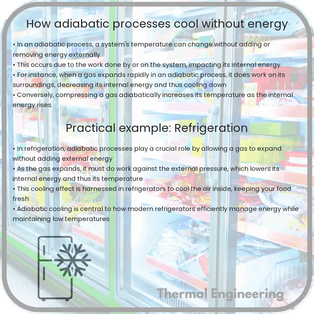
Adiabatic cooling is a thermodynamic process in which a fluid’s temperature decreases without any heat being transferred into or out of the fluid system. This concept is pivotal in both natural phenomena and various engineering applications, such as air conditioning, gas compression, and even meteorology. To grasp how adiabatic cooling works, we must first delve into the basics of what ‘adiabatic’ means and how these processes function in practical scenarios.

What Does Adiabatic Mean?

In thermodynamic terms, an adiabatic process is one where no heat is transferred into or out of a system, signified by Q = 0, where Q represents the heat exchange. This can occur either because the system is thermally insulated, preventing heat exchange with its surroundings, or because the process happens too quickly for any heat transfer to take place. In both scenarios, any change in temperature of the system must arise from work done by or on the system rather than from external heating or cooling.

How Does Adiabatic Cooling Occur?

Adiabatic cooling occurs when a gas expands. According to the first law of thermodynamics, the energy within a closed system must remain constant if no heat is transferred. This law can be mathematically expressed as:

ΔU = Q – W

where ΔU is the change in internal energy of the gas, Q is the heat added to the system, and W is the work done by the system. In an adiabatic process, Q = 0, so the equation simplifies to:

ΔU = -W

When a gas expands adiabatically, it does work on its surroundings. This work comes from its internal energy, which leads to a decrease in temperature. The exact relationship between pressure, volume, and temperature in an ideal gas undergoing an adiabatic process is given by the following equation:

PVγ = constant

where P is the pressure, V is the volume, and γ (gamma) is the heat capacity ratio (Cp/Cv, the ratio of heat capacity at constant pressure to heat capacity at constant volume).

Examples of Adiabatic Cooling in Engineering and Nature

  • Refrigeration Cycles: Modern refrigerators and air conditioners use a controlled adiabatic process in the expansion valve, where the refrigerant expands and cools before absorbing heat from the interior of the refrigerator or the room.
  • Gas Compression and Turbines: In gas turbine engines, the compression stage is typically adiabatic. The compressed air heats up as it is compressed by doing work on it.
  • Cloud Formation: As moist air rises in the atmosphere, it expands due to lower atmospheric pressure at higher altitudes, leading to adiabatic cooling, which can cause water vapor to condense and form clouds.

Significance of Adiabatic Cooling

Adiabatic cooling is an essential principle in thermodynamics that exemplifies how physical systems can regulate temperature and undergo phase changes without external heat exchange. Understanding this process is fundamental for designing efficient cooling systems and for predicting weather patterns. In a broader context, it enhances our comprehension of energy conservation and the behavior of gases under varying pressures and volumes.

By harnessing the principles of adiabatic cooling, engineers can devise more efficient systems while also contributing to sustainable practices in technology and environmental management.

How does a phase change material absorb heat

Learn how Phase Change Materials (PCMs) absorb and store heat through phase changes, vital for enhancing energy efficiency in various applications.

How does a phase change material absorb heat

Understanding How Phase Change Materials Absorb Heat

Phase Change Materials (PCMs) play a crucial role in many engineering fields by managing heat in systems ranging from building materials to thermal management in electronics. The fundamental concept behind PCMs is based on their ability to absorb or release significant amounts of heat while transitioning through different phases—typically from solid to liquid or vice versa. This process helps in stabilizing temperature within a particular environment.

How PCMs Work

At a basic level, the ability of a PCM to absorb heat is strongly tied to the material’s latent heat properties. Latent heat refers to the energy absorbed or released by a substance during a phase change without a corresponding change in temperature. Here’s a step-by-step explanation:

  1. Absorption of Heat: When the environment’s temperature rises to a certain threshold, the PCM starts absorbing heat. This absorption continues until the PCM reaches its melting point.
  2. Phase Transition: Upon reaching the melting point, the PCM undergoes a phase change from solid to liquid. It continues to absorb heat but the temperature of the material does not increase during this phase change. This temperature at which the phase change occurs is known as the material’s melting point.
  3. Storage of Heat: The heat absorbed during the phase change is stored within the material as latent heat. The amount of heat that can be stored depends on the latent heat capacity of the PCM.

This process can be mathematically described using the equation Q = m * L, where:

  • Q is the amount of heat absorbed,
  • m is the mass of the PCM,
  • L is the latent heat capacity of the PCM.

Types of PCMs

PCMs are categorized based on their phase change cycle, predominantly either organic, inorganic, or eutectic compounds:

  • Organic PCMs: Includes paraffin waxes and fatty acids, known for their reliable melting points and minimal supercooling.
  • Inorganic PCMs: Includes salt hydrates which offer higher latent heat per unit volume but may experience phase segregation.
  • Eutectic PCMs: A mixture of two or more materials that, when mixed in the right proportions, melt and solidify at a single temperature. These have sharp melting points and good thermal conductivity.

Applications of Phase Change Materials

The unique capabilities of PCMs to manage heat make them extremely useful in various applications:

  • Building and Construction: PCMs incorporated into building materials help in maintaining indoor temperatures, reducing the reliance on HVAC systems, and enhancing energy efficiency.
  • Thermal Energy Storage: PCMs are used in thermal batteries for storing solar heat or waste heat from industrial processes, which can then be reused.
  • Electronic Devices: Used in devices to regulate temperature and prevent overheating, thus extending the device’s life and performance.

Understanding the mechanisms through which PCMs absorb heat not only pushes advancements in thermal management technologies but also contributes to broader sustainability practices by improving energy efficiency across various systems.

How thermal conductivity affects heat flow

Learn about thermal conductivity, a key material property defining heat transfer rates via conduction, its influencing factors, and engineering applications.

How thermal conductivity affects heat flow

Understanding Thermal Conductivity and Heat Flow in Materials

Thermal conductivity is a property of materials that describes their ability to conduct heat. It plays a critical role in various engineering applications, from building insulation and thermal management systems in electronics to manufacturing processes. To understand how thermal conductivity affects heat flow, it’s essential to grasp a few fundamental concepts in the physical behavior of materials in response to temperature differences.

Basics of Heat Transfer

Heat is energy that transfers from one body or substance to another as a result of a temperature difference. The three basic modes of heat transfer are conduction, convection, and radiation. In this discussion, we focus on conduction, where heat transfer occurs through materials without the movement of the material itself.

What is Thermal Conductivity?

Thermal conductivity (represented by the symbol ‘k’) is a measure of a material’s ability to conduct heat. It quantifies the amount of heat that passes through a material with a certain area and thickness over a specific temperature gradient. The standard unit of thermal conductivity in the International System of Units (SI) is watts per meter Kelvin (W/m*K).

Formula for Heat Transfer through Conduction

The basic equation used to calculate the heat transfer rate (Q) through conduction is:

Q = k * A * (T2 – T1) / d

  • Q is the rate of heat transfer (watts, W)
  • k is the thermal conductivity of the material (W/m*K)
  • A is the cross-sectional area of the material perpendicular to the direction of heat transfer (square meters, m2)
  • T2 – T1 is the temperature difference across the material (Kelvin, K)
  • d is the thickness of the material in the direction of heat flow (meters, m)

Factors Affecting Thermal Conductivity

The thermal conductivity of a material depends on several factors, including:

  • Material Composition: Metals typically have higher thermal conductivity than insulators. For example, copper and aluminum are excellent heat conductors, whereas wood and glass are much less so.
  • Temperature: The thermal conductivity can vary with temperature. In general, for metals, it decreases as temperature increases, whereas for insulators, it might increase with rising temperature.
  • Impurities and Material Structure: The presence of impurities and defects in the material structure can lower thermal conductivity because they scatter the heat carriers (usually electrons and phonons), impeding the flow of heat.

Applications and Implications of Thermal Conductivity

In engineering, controlling and managing thermal conductivity is crucial in designing systems that require effective heat transfer or insulation. Here are a few examples:

  • Building Construction: Materials with low thermal conductivity are used for insulation in buildings to reduce energy costs by maintaining indoor temperature without excessive heating or cooling.
  • Electronics: Effective heat dissipation is critical in electronic devices to prevent overheating and ensure proper function. Materials with high thermal conductivity, such as copper and aluminum, are often used to manufacture heat sinks and other cooling components.
  • Aerospace: Thermal protection systems in spacecraft are designed considering thermal conductivity to protect sensitive components from extreme temperatures during operations like re-entry or while orbiting close to the sun.

Understanding thermal conductivity and its effects on heat flow allows engineers to make informed decisions in materials selection and system design, ensuring safety, efficacy, and efficiency in various applications.

How heat transfer fluids enhance systems

Explore the critical role of heat transfer fluids in system efficiency, including types like water, mineral oils, synthetic fluids, and refrigerants.

How heat transfer fluids enhance systems

Understanding Heat Transfer Fluids and Their Role in Enhancing Systems

Heat transfer fluids are essential components in various industrial and engineering applications. They are used to move thermal energy from one place to another in heating, cooling, and power generation systems. In this article, we’ll explore what heat transfer fluids are, the different types available, and how they enhance system efficiency and effectiveness.

What are Heat Transfer Fluids?

Heat transfer fluids (HTFs) are liquids or gases specially formulated to carry heat in thermal management systems. These fluids typically have high thermal conductivity and a high heat capacity, allowing them to absorb and transport heat effectively. They are crucial in applications ranging from simple cooling systems in automobiles to complex processes in chemical plants and solar power stations.

Types of Heat Transfer Fluids

  • Water: The most common and cost-effective heat transfer fluid, water is excellent due to its high heat capacity and thermal conductivity. However, its use is limited by its boiling point and freezing point, which can be altered with additives like glycols.
  • Mineral Oils: These are used in applications that require higher temperature ranges than water can accommodate. Mineral oils can operate at higher temperatures without decomposing, making them suitable for industrial heating systems.
  • Synthetic Fluids: These fluids are engineered to provide superior thermal stability at high temperatures and are commonly used in applications requiring precise temperature control. They include silicones and aromatic hydrocarbons.
  • Refrigerants: Used primarily in cooling and refrigeration systems, refrigerants undergo phase changes from liquid to gas and back, which is highly effective for heat transfer. Examples include Freon and ammonia.

How Heat Transfer Fluids Enhance Systems

Improving the efficiency and longevity of thermal management systems is one of the principal advantages of using the right heat transfer fluid. Several factors illustrate how these fluids enhance system performance:

  1. Efficient Heat Transfer: Good heat transfer fluids have properties such as high thermal conductivity, which enables faster and more efficient heat transfer. This property ensures that systems can achieve rapid heating or cooling, leading to increased process efficiency.
  2. Temperature Control: HTFs are capable of stable performance across a wide range of temperatures. This stability helps maintain the desired temperature set points precisely, crucial for process industries where specific temperatures are essential for chemical reactions or other operations.
  3. System Longevity: By maintaining stable operating temperatures and providing effective heat removal, heat transfer fluids reduce thermal stress on system components. This minimization of wear and tear extends the lifetime of the equipment, reducing maintenance costs and downtime.
  4. Energy Efficiency: Efficient transfer of heat also means less energy is wasted. Systems using optimized HTFs can reduce energy consumption compared to systems that operate less efficiently due to poor heat transfer properties.

Understanding the chemistry and physics behind heat transfer fluids allows engineers to choose and tailor fluids specifically suited to their needs. Whether it’s a simple car radiator or a complex industrial furnace, the judicious selection and management of HTFs play a crucial role in system performance and energy efficiency.

Conclusion

The use of heat transfer fluids spans a myriad of applications across various industries. By properly understanding and utilizing these fluids, we can significantly enhance the effectiveness and efficiency of thermal management systems. This not only ensures better performance but also contributes to energy conservation and operational cost reductions. Therefore, heat transfer fluids are indispensable in the design and operation of systems where temperature regulation and heat transfer are critical.

Cryogenic treatment of metals

Delve into the intricacies of cryogenic treatment of metals, a process that greatly enhances durability, wear resistance, and performance of metal components.

Cryogenic treatment of metals

Understanding Cryogenic Treatment of Metals

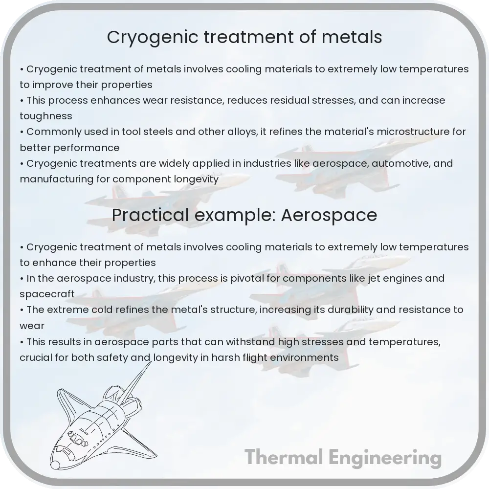
Cryogenic treatment of metals is a process that uses extremely low temperatures to enhance the properties of metal materials. This treatment is typically applied to tools, dies, and other components with a goal of improving their durability, wear resistance, and overall performance. Here’s an overview of how this process works and why it’s beneficial in various engineering applications.

What is Cryogenic Treatment?

Cryogenic treatment involves cooling metals down to cryogenic temperatures typically around -190°C (-310°F) or lower using liquid nitrogen. Once the metal reaches these temperatures, it is maintained in this state for a specified period, ranging from several hours to days, before it is gradually brought back to room temperature. This extreme cooling and slow return to normal temperature are what lead to changes at the microstructural level of the metals.

Steps in Cryogenic Treatment

  1. Precooling Phase: The metal is cooled down slowly to avoid thermal shock and to ensure uniform temperature distribution throughout its structure.
  2. Soaking Phase: Upon reaching the desired cryogenic temperature, the metal is held at this temperature to allow the transformation processes to occur completely.
  3. Warming Back to Room Temperature: After the soaking phase, the metal is slowly returned to room temperature, either in ambient air or using controlled heating methods.
  4. Post-Treatment Heat Application: Depending on the type of metal and its intended use, a further heat treatment like tempering may be applied to stabilize the microstructure.

Effects of Cryogenic Treatment on Metal Properties

Cryogenic treatment has several beneficial effects on metals:

  • Increase in Wear Resistance: The treatment transforms retained austenite into martensite, which is a harder phase. This increases the wear resistance of the metal.
  • Improved Durability: The internal stress within the metal is reduced, improving the life and durability of the material under dynamic stresses.
  • Enhanced Dimensional Stability: Changes at the microstructural level can result in fewer tendencies for the metal to distort under heat and mechanical stress.

Applications of Cryogenic Treatment

Cryogenic treatment is used in various areas including:

  • Tooling: Drills, end mills, and other cutting instruments are commonly treated to increase their service life and performance.
  • Automotive: Components such as gears, bearings, and brake rotors are treated to enhance their wear properties and endurance.
  • Electronics: Certain metals used in electronic connectors and other components can undergo cryogenic treatment to improve electrical conductivity and fatigue resistance.

In conclusion, cryogenic treatment of metals is a remarkable example of how advanced material science can dramatically improve the characteristics of metal. By manipulating the microstructure at extremely low temperatures, engineers can create components that are more durable, stable, and efficient, satisfying the increasing demands of modern engineering applications.

How thermal imaging cameras detect heat

Learn how thermal imaging cameras utilize infrared technology to detect and display heat emissions from objects, aiding in various applications like firefighting and diagnostics.

How thermal imaging cameras detect heat

Understanding How Thermal Imaging Cameras Detect Heat

Thermal imaging cameras are fascinating tools used in a variety of fields, from firefighting and surveillance to energy auditing and maintenance. These devices do not see light as we do; instead, they detect heat emitted by objects. They convert this heat, or infrared energy, into visible light to display the temperature variations of an object or scene. Let’s dive into the fundamentals of how these cameras work and explore their applications.

The Science Behind Thermal Imaging

All objects emit infrared energy as heat. The hotter an object is, the more infrared radiation it emits. This principle is at the core of thermal imaging technology. Thermal imaging cameras detect this infrared radiation and convert it into an electrical signal, which is then processed to form a thermal image on a display.

The key components of a thermal imaging camera include:

  • Infrared Sensor: This sensor detects infrared radiation in its field of view. The quality of the sensor determines the resolution and sensitivity of the camera.
  • Optical Component: Lenses direct the infrared radiation onto the sensor. These lenses are typically made from materials like Germanium, which are transparent to infrared wavelengths but not to visible light.
  • Signal Processing Unit: This converts the data from the infrared sensor into a format that can be displayed as an image. It adjusts the image for factors like contrast and range.
  • Display: Finally, the processed image is rendered on the camera’s display, showing a heatmap of temperature variations. Different temperatures are often shown in different colors, enhancing visibility and interpretation.

How Thermal Imaging Cameras Display Heat

Thermal imaging cameras translate the intensity of infrared radiation into a range of colors that represent different temperatures. This is done through a process called thermography. Commonly, warmer objects appear as lighter colors (whites and yellows), while cooler objects appear in darker colors (blues and purples).

The temperature scale used in a thermal image is set either automatically by the camera or manually by the user. This scale is crucial for interpreting the thermal image correctly, as it defines what each color means in terms of temperature.

Enhanced features such as high dynamic range (HDR) imaging might be employed to show greater detail in scenes that have a wide range of temperatures, ensuring that both hot and cold areas are visible and differentiated.

Applications of Thermal Imaging Technology

Thermal imaging cameras have a broad spectrum of applications, proving their versatility and utility in various sectors:

  • Firefighting: Firefighters use thermal imaging to see through smoke, locate persons, and identify the base of fires.
  • Military and Surveillance: These cameras provide nighttime and forested area surveillance capabilities.
  • Building Inspections: Experts use thermal cams to find heat leaks in insulated buildings and to monitor and diagnose electrical or mechanical systems.
  • Medical and Veterinary: These tools help in the detection of fevers and in monitoring blood flow disorders.
  • Automotive: Enhanced visibility for night driving and the ability to detect and monitor the heat of various vehicle components are key uses in this sector.

In summary, thermal imaging cameras are powerful devices that offer detailed insights based on the heat emitted by objects. This technology relies on the fundamental laws of physics related to infrared radiation, providing invaluable information across many fields, from safety and security to healthcare and mechanical integrity analysis.

How thermoelectric generators convert heat

An in-depth exploration of thermoelectric generators, how they harness the Seebeck effect to convert heat into electricity, their components, working mechanism, and diverse applications.

How thermoelectric generators convert heat

Understanding Thermoelectric Generators

Thermoelectric generators (TEGs) are innovative devices that convert thermal energy—simply, heat—directly into electrical energy. This process of energy conversion makes use of the physical phenomenon known as the Seebeck effect. Unlike traditional power generation methods that often involve moving parts and complex mechanisms, thermoelectric generators operate silently with no moving parts, making them highly reliable and low-maintenance. In this article, we explore how these devices work and their practical applications.

The Basics of the Seebeck Effect

The foundational principle behind thermoelectric generators is the Seebeck effect, discovered by German scientist Thomas Johann Seebeck in 1821. The Seebeck effect occurs when two different conductive materials are connected in a circuit and there is a temperature difference between the junctions. This temperature difference creates a voltage difference, which can drive an electric current through the circuit.

In more technical terms, the voltage difference, and hence the generated electric current, is directly proportional to the temperature difference between the hot and cold sides of the thermoelectric materials. Mathematically, this relationship is expressed as:

\[ V = S \times \Delta T \]

Where:

  • V is the voltage generated,
  • S represents the Seebeck coefficient, which varies based on the materials used, and
  • \(\Delta T\) is the temperature difference across the materials.

Components of a Thermoelectric Generator

A typical thermoelectric generator consists of:

  • Thermoelectric modules: These modules are the heart of TEGs and usually consist of pairs of p-type and n-type semiconductor materials that are connected electrically in series and thermally in parallel. Each pair forms a thermocouple.
  • Heat source: Provides the necessary thermal energy to create the temperature gradient required for generating electricity.
  • Heat sink: Absorbs the unused heat from the cold side of the thermocouples, helping to maintain the temperature gradient.

How a Thermoelectric Generator Works

When a TEG is exposed to a heat source, the heat is absorbed by the hot side of the thermoelectric modules. This heat is not completely transferred to the cold side, which is attached to a heat sink. The resulting temperature difference creates a voltage across each thermocouple due to the Seebeck effect. The electric current generated by each thermocouple is harnessed and can be used to power electrical devices or recharge batteries.

Applications of Thermoelectric Generators

Thermoelectric generators have a variety of applications including:

  • Spacecraft power supply: Due to their reliability and long life, TEGs are ideal for powering spacecraft and satellites where maintenance is impossible.
  • Waste heat recovery: Industries that produce a large amount of waste heat, such as manufacturing and power plants, can use TEGs to recuperate some of that energy and convert it into usable electricity.
  • Remote power: TEGs provide electricity in remote locations where conventional power sources are not feasible, such as remote weather stations and unmanned aerial vehicles.

Thermoelectric generators exemplify an exciting application of thermodynamics and material science that turns waste heat – often an unavoidable byproduct in many processes – into a valuable resource. With advancements in materials science, the efficiency and application scope of thermoelectric generators are expected to expand, potentially playing a critical role in future energy systems.

How does a hydrofoil reduce drag

Learn how hydrofoils enhance speed and efficiency in watercraft by lifting hulls above the surface to significantly reduce drag forces.

How does a hydrofoil reduce drag

Understanding Hydrofoils: How They Reduce Drag

Hydrofoils are a type of engineering marvel that allow boats and other watercraft to achieve higher speeds and improved efficiency. They achieve this by lifting a vessel’s hull above the water’s surface, drastically reducing drag. In this article, we will explore what drag is, how hydrofoils are designed, and the physics behind how they reduce drag.

What is Drag?

Drag is a force that acts opposite to the direction of movement through a fluid, which in the case of watercraft, is water. This resistance is caused by friction and differences in pressure and generally, has two components: skin friction drag and form drag. Skin friction drag is due to the friction between the water and the surface of the vessel, whereas form drag is caused by the water’s resistance against the shape of the vessel.

Design and Functionality of Hydrofoil

A hydrofoil is essentially a wing that operates underwater. Much like an airplane wing, it has a special shape called an airfoil that alters the pressure distribution around it as it moves through water. When water passes over the hydrofoil, it generates lift perpendicular to the direction of flow, similar to how an airplane’s wings generate lift as they move through the air.

  • Lift: This is generated due to differences in pressure on the top and bottom surfaces of the hydrofoil. The shape of the hydrofoil is such that it causes water flowing over the top surface to accelerate and decrease in pressure, according to Bernoulli’s Principle, which states that an increase in the speed of the fluid occurs simultaneously with a decrease in pressure.
  • Thrust: Some advanced hydrofoil designs also generate thrust through propellers or jets that further enhance the speed of the vessel.

How Hydrofoils Reduce Drag

By lifting the hull of the watercraft above the surface of the water, hydrofoils significantly reduce both forms of drag:

  1. Reduction in Skin Friction Drag: When a vessel is supported by hydrofoils, a substantial portion of the hull is no longer in contact with the water. Since skin friction drag is a product of the contact area between the vessel’s hull and the water, minimizing this contact decreases the drag from skin friction.
  2. Reduction in Form Drag: With the hull above the water surface, the hydrodynamic shape of the hull contributes less to the overall form drag. The effective area subjected to form drag is notably reduced, as the smaller, streamlined hydrofoils navigate through the water instead of the entire hull.

In practical terms, this reduction in drag results in higher speeds and lower fuel consumption, making hydrofoil-equipped vessels more efficient than conventional ones. The effectiveness of hydrofoils is particularly evident in high-speed applications, such as ferries and racing boats, where efficiency and speed are critical.

Conclusion

Hydrofoils represent a significant advancement in naval engineering, allowing vessels to achieve higher speeds and increased operational efficiency by effectively reducing drag. Their design leverages fundamental principles of physics to lift a vessel above the water, minimizing resistance and maximizing performance. As technology advances, we can expect hydrofoils to become even more prevalent in various maritime applications.

Whether for commercial or recreational use, the principles behind hydrofoils demonstrate the fascinating ways that engineering and physics can combine to solve practical problems—such as reducing drag to improve the speed and efficiency of waterborne transport.