Facebook Instagram Youtube Twitter

Thermal energy storage materials

Dive into the mechanics and benefits of thermal energy storage materials, essential for sustainable energy management and applications.

Thermal energy storage materials

Understanding Thermal Energy Storage Materials

Thermal energy storage (TES) is a technology that is gaining attention as we move towards more sustainable energy practices. It involves storing heat or cold that can be used at a later time, offering a variety of benefits, from improving the efficiency of energy use to reducing emissions. In this article, we’ll explore what thermal energy storage materials are, how they work, and their applications in everyday life.

Types of Thermal Energy Storage Materials

Thermal energy can be stored in several ways, using different categories of materials based on their storage method: sensible heat storage materials, latent heat storage materials, and thermochemical materials.

  • Sensible Heat Storage Materials: These materials store energy by changing their temperature without undergoing a phase change. Common examples include water, sand, and stones. The amount of energy stored is proportional to the material’s mass (m), specific heat capacity (c), and the change in temperature (∆T), as given by the equation Q = m*c*∆T, where Q is the stored thermal energy.
  • Latent Heat Storage Materials: These store energy during phase change processes, typically from solid to liquid or from liquid to gaseous state. Materials like paraffin waxes and salt hydrates are prominent due to their high energy storage density during melting and solidification. The energy storage is primarily computed based on the material’s latent heat capacity.
  • Thermochemical Storage Materials: This approach involves endothermic and exothermic chemical reactions for energy storage and release. These materials, such as metal hydrides and calcium oxide, can store heat over a long period without significant losses.

Applications of Thermal Energy Storage

TES systems have versatile applications across numerous sectors:

  • Power Generation: TES can be used to store excess energy generated during non-peak times (such as from wind or solar energy), and then used during peak demand, enhancing grid stability and efficiency.
  • Building Heating and Cooling: Incorporating TES in buildings can significantly reduce the energy needed for heating and cooling. By absorbing heat during the day (cooling) and releasing it at night (heating), TES can help maintain comfortable indoor temperatures more efficiently.
  • Industrial Applications: Many industrial processes require large amounts of thermal energy. TES can provide this energy more consistently, helping to reduce the reliance on fossil fuels and decrease operational costs.

Advantages of Thermal Energy Storage

TES offers several compelling advantages:

  • Energy Efficiency: Maximizing the use of available thermal energy and reducing wastage.
  • Cost-Effective: By managing energy demand, TES systems can reduce costs related to energy consumption and infrastructure stress during peak times.
  • Environmental Benefits: TES systems help in reducing carbon emissions by optimizing the use of renewable energy sources and decreasing the reliance on non-renewable sources.

Understanding and utilizing thermal energy storage materials can lead to more efficient use of energy, economic savings, and a significant reduction in environmental impact. As technology progresses and our understanding deepens, the role of TES materials in energy systems is likely to become more vital.

Incorporating these innovative solutions in engineering projects not only furthers technological advancement but also supports the global shift towards sustainability. Whether in large-scale industrial applications or smaller scale residential usage, thermal energy storage materials hold the key to optimizing energy usage for a brighter, cleaner future.
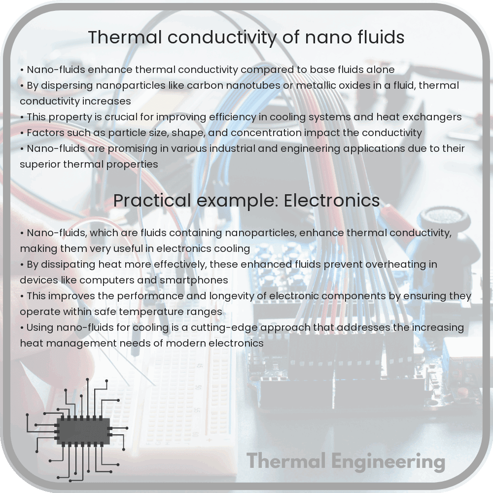
Thermal conductivity of nano-fluids

Delve into the enhanced thermal conductivity of nano-fluids and their significant impact on engineering thermal management systems.

Thermal conductivity of nano-fluids

Understanding Thermal Conductivity in Nano-fluids

Thermal conductivity is a key concept in the field of engineering, particularly when it comes to the design and efficiency of heating, cooling, and thermal management systems. The advent of nano-fluids has brought fresh perspectives and capabilities to this area. Nano-fluids are fluids that contain nanometer-sized particles, often called nanoparticles. These suspended particles can significantly alter the thermal properties of the base fluid. This article will explore how nano-fluids enhance thermal conductivity and the implications this has for real-world applications.

What Are Nano-fluids?

Nano-fluids are typically made by suspending nanoparticles—materials with sizes on the order of 10-9 meters—in conventional liquids such as water, oil, or ethylene glycol. The particles used can be metals, metal oxides, carbides, or carbon nanotubes, each impacting the fluid’s properties in different ways.

Enhancement of Thermal Conductivity

The primary reason nano-fluids are so intriguing is their enhanced thermal conductivity compared to the base fluids without nanoparticles. Thermal conductivity is a measure of a material’s ability to conduct heat. The presence of nanoparticles increases this ability, which can be particularly useful in applications where efficient heat transfer is crucial.

How Does Nano-sizing Affect Conductivity?

At the nanoscale, the surface area to volume ratio of particles increases significantly. This means that a greater area of the particle is exposed to the fluid, enhancing the interactions between the particle and the fluid molecules. These interactions facilitate better energy transfer mechanisms from the hot to the cooler parts of the fluid, thereby improving the overall thermal conductivity.

Models of Thermal Conductivity in Nano-fluids

Several theoretical models have been developed to predict the thermal conductivity of nano-fluids. These include the classical Maxwell model, which was originally developed for fibrous materials but has been adapted for nano-fluids. It undertakes the effective medium theory where the fluid and particles are considered a single, homogeneous medium. The model is given by:

knf = kf [1 + 3φ(κ – 1) / (κ + 2)]

Here, knf is the thermal conductivity of the nano-fluid, kf is the thermal conductivity of the base fluid, φ is the volume fraction of nanoparticles, and κ is the ratio of the thermal conductivity of the particle to that of the fluid.

Real-world Applications

Nano-fluids are used in a wide range of applications. One of the most common uses is in cooling systems for electronic devices, such as computers and smartphones, where efficient heat dissipation is essential for performance and longevity. They are also increasingly used in HVAC systems to enhance heat transfer, thereby improving energy efficiency.

Challenges and Future Prospects

Despite their advantages, there are challenges in the widespread adoption of nano-fluids. One major issue is the stability of suspended nanoparticles. Over time, particles might settle, leading to inconsistency in fluid properties. Researchers are actively exploring surfactants and surface treatments to improve stability. Additionally, the impact of nanofluids on the environment and health needs further assessment.

As research progresses, understanding and harnessing the unique properties of nano-fluids could lead to significant advances in thermal management technologies, making them more efficient, sustainable, and capable of meeting the needs of modern engineering demands.

Conclusion

The exploration of nano-fluids showcases an exciting convergence of nanotechnology and fluid mechanics, underscoring a broader engineering trend towards materials and systems that are specifically engineered at the molecular level to achieve superior performance. As thermal management challenges grow in complexity and scale, nano-fluids represent a promising solution that could reshape conventional approaches to heat transfer.

Advanced cooling methods for nuclear reactors

Learn about innovative cooling technologies enhancing the safety and efficiency of nuclear reactors, including passive systems, advanced coolants, and modern safety designs.

Advanced cooling methods for nuclear reactors

Advanced Cooling Methods for Nuclear Reactors

Nuclear reactors are complex machines that generate a significant amount of heat during the process of nuclear fission. Removing this heat effectively and efficiently is crucial not only for generating electricity but also for ensuring the safety and longevity of the reactor. Here, we look at some advanced cooling methods that have been developed to enhance the cooling performance and safety of nuclear reactors.

1. Passive Cooling Systems

Unlike traditional active cooling systems that rely on electric-powered pumps and motors to circulate coolant, passive cooling systems use natural forces such as gravity and natural convection. These systems can operate without external power, making them highly reliable in emergency situations. A well-known example of this technology can be found in the AP1000 reactor design by Westinghouse, which features a passive residual heat removal system.

  • Natural Convection: Heated water rises naturally, and cooler water descends, creating a natural circulation that does not require mechanical pumps.
  • Heat Pipes: These use a sealed, evacuated tube that contains a working fluid. Heat is absorbed at one end, causing the fluid to evaporate and carry the heat away where it condenses, releasing the heat. This cycle does not require external energy.

2. Advanced Coolant Options

Traditional nuclear reactors use water as a coolant. However, newer designs explore other materials that can handle higher temperatures and provide better thermal efficiency.

  1. Molten Salt: These coolants, typically a mix of fluoride or chloride salts, offer high boiling points and good heat transport capabilities. Molten salt coolants are often used in molten salt reactors (MSRs).
  2. Liquid Metal: Coolants like sodium or lead are used because of their excellent heat-conducting properties. For instance, sodium has a high boiling point and thermally conductive properties, making it effective at transferring heat away from the reactor core.

3. Heat Exchangers Enhancement

Heat exchangers play a crucial role in transferring heat away from the nuclear reactor to a secondary fluid that can then be used to generate steam and electricity. Engineers are working on enhancing these systems to improve safety and efficiency.

  • Advanced Materials: Developing and utilizing materials with higher thermal conductivity and corrosion resistance to increase the longevity and effectiveness of heat exchangers.

4. Integrated Safety Systems

Modern reactor designs integrate advanced cooling systems with safety protocols to automatically shut down the reactor in case of an emergency and to facilitate the cooling process without human intervention.

  • Emergency Core Cooling Systems (ECCS): These systems are designed to automatically provide water to the reactor’s core in case the regular cooling fails. They are essential for preventing core melt accidents.
  • Containment Cooling: Enhanced containment structures are equipped with cooling systems that manage the heat and pressure levels within the containment, even after a reactor shutdown.

Advanced cooling methods are pivotal for the evolution of nuclear reactor technology. By improving efficiency and safety, these innovations not only support the production of clean energy but also help in mitigating the risks associated with nuclear power generation. As technology progresses, the goal remains clear: to harness nuclear energy in the safest and most efficient manner possible.

What is Organic Insulation Material – Definition

The organic insulation materials treated in this section are all derived from a petrochemical or renewable feedstock (bio-based). Organic Insulation Materials

Insulation Materials

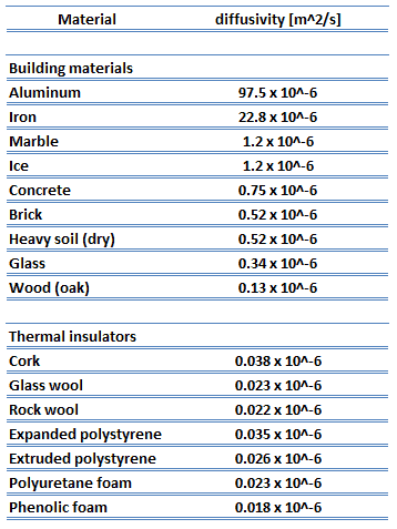
Thermal Insulators - ParametersAs was written, thermal insulation is based on the use of substances with very low thermal conductivity. These materials are known as insulation materials. Common insulation materials are wool, fiberglass, rock wool, polystyrene, polyurethane, and goose feather etc. These materials are very poor conductors of heat and are therefore good thermal insulators.


Types of Insulation – Categorization of Insulation Materials

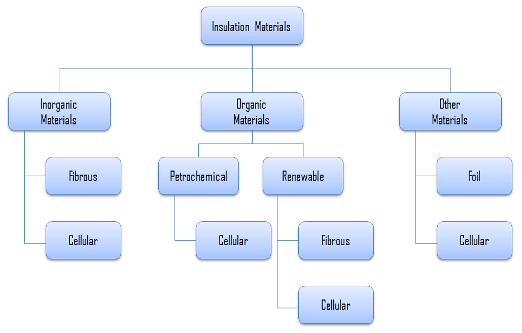
For insulation materials, three general categories can be defined. These categories are based on the chemical composition of the base material from which the insulating material is produced.

Insulation Materials - Types

In further reading, there is a brief description of these types of insulation materials.

Organic Insulation Materials

The organic insulation materials treated in this section are all derived from a petrochemical or renewable feedstock (bio-based). Almost all of the petrochemical insulation materials are in the form of polymers. As can be see from the figure, all petrochemical insulation materials are cellular. A material is cellular when the structure of the material consists of pores or cells. On the other hand, many plants contain fibres for their strength, therefore almost all the bio-based insulation materials are fibrous (except expanded cork, which is cellular).

Organic insulation materials can be classified accordingly:

Other Insulation Materials

Example of Insulation – Polystyrene

Generally, polystyrene is a synthetic aromatic polymer made from the monomer styrene, which is derived from benzene and ethylene, both petroleum products. Polystyrene can be solid or foamed. Polystyrene is a colorless, transparent thermoplastic, which is commonly used to make foam board or beadboard insulation and a type of loose-fill insulation consisting of small beads of polystyrene. Polystyrene foams are 95-98% air. Polystyrene foams are good thermal insulators and are therefore often used as building insulation materials, such as in insulating concrete forms and structural insulated panel building systems. Expanded (EPS) and extruded polystyrene (XPS) are both made from polystyrene, but EPS is composed of small plastic beads that are fused together and XPS begins as a molten material that is pressed out of a form into sheets. XPS is most commonly used as foam board insulation.

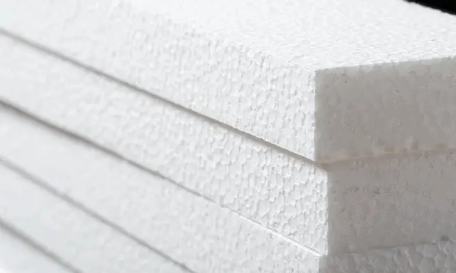
expanded polystyrene - thermal insulationExpanded polystyrene (EPS) is a rigid and tough, closed-cell foam. Building and construction applications account for around two-thirds of demand for expanded polystyrene. It is used for the insulation of (cavity) walls, roofs and concrete floors. Due to its technical properties such as low weight, rigidity, and formability, expanded polystyrene can be used in a wide range of applications, for example trays, plates and fish boxes.

Although both expanded and extruded polystyrene have a closed-cell structure, they are permeable by water molecules and can not be considered a vapor barrier. In expanded polystyrene there are interstitial gaps between the expanded closed-cell pellets that form an open network of channels between the bonded pellets. If the water freezes into ice, it expands and can cause polystyrene pellets to break off from the foam.

 
References:
Heat Transfer:
  1. Fundamentals of Heat and Mass Transfer, 7th Edition. Theodore L. Bergman, Adrienne S. Lavine, Frank P. Incropera. John Wiley & Sons, Incorporated, 2011. ISBN: 9781118137253.
  2. Heat and Mass Transfer. Yunus A. Cengel. McGraw-Hill Education, 2011. ISBN: 9780071077866.
  3. U.S. Department of Energy, Thermodynamics, Heat Transfer and Fluid Flow. DOE Fundamentals Handbook, Volume 2 of 3. May 2016.

Nuclear and Reactor Physics:

  1. J. R. Lamarsh, Introduction to Nuclear Reactor Theory, 2nd ed., Addison-Wesley, Reading, MA (1983).
  2. J. R. Lamarsh, A. J. Baratta, Introduction to Nuclear Engineering, 3d ed., Prentice-Hall, 2001, ISBN: 0-201-82498-1.
  3. W. M. Stacey, Nuclear Reactor Physics, John Wiley & Sons, 2001, ISBN: 0- 471-39127-1.
  4. Glasstone, Sesonske. Nuclear Reactor Engineering: Reactor Systems Engineering, Springer; 4th edition, 1994, ISBN: 978-0412985317
  5. W.S.C. Williams. Nuclear and Particle Physics. Clarendon Press; 1 edition, 1991, ISBN: 978-0198520467
  6. G.R.Keepin. Physics of Nuclear Kinetics. Addison-Wesley Pub. Co; 1st edition, 1965
  7. Robert Reed Burn, Introduction to Nuclear Reactor Operation, 1988.
  8. U.S. Department of Energy, Nuclear Physics and Reactor Theory. DOE Fundamentals Handbook, Volume 1 and 2. January 1993.
  9. Paul Reuss, Neutron Physics. EDP Sciences, 2008. ISBN: 978-2759800414.

Advanced Reactor Physics:

  1. K. O. Ott, W. A. Bezella, Introductory Nuclear Reactor Statics, American Nuclear Society, Revised edition (1989), 1989, ISBN: 0-894-48033-2.
  2. K. O. Ott, R. J. Neuhold, Introductory Nuclear Reactor Dynamics, American Nuclear Society, 1985, ISBN: 0-894-48029-4.
  3. D. L. Hetrick, Dynamics of Nuclear Reactors, American Nuclear Society, 1993, ISBN: 0-894-48453-2.
  4. E. E. Lewis, W. F. Miller, Computational Methods of Neutron Transport, American Nuclear Society, 1993, ISBN: 0-894-48452-4.

See also:

Heat Losses

We hope, this article, Organic Insulation Material, helps you. If so, give us a like in the sidebar. Main purpose of this website is to help the public to learn some interesting and important information about thermal engineering.

What is Facade Insulation – External Wall Insulation – Definition

Facade insulation is a thermally insulated, protective, decorative exterior cladding procedure involving the use of various of insulation materials. Thermal Engineering

Facade Insulation – External Wall Insulation

A major source of heat loss from a house is through walls and facade. Facade insulation is a thermally insulated, protective, decorative exterior cladding procedure involving the use of expanded polystyrene insulation, glass or rock wool, polyurethane foam or phenolic foam, topped off with a reinforced cement based, mineral or synthetic finish and plaster.

The purpose of facade insulation is to reduce the overall heat transfer coefficient by adding materials with low thermal conductivity.  External wall insulation in buildings is an important factor to achieving thermal comfort for its occupants. External wall insulation as well as other types of insulation reduce unwanted heat loss and also reduce unwanted heat gain. They can significantly decrease the energy demands of heating and cooling systems. It must be added, there is no material which can completely prevent heat losses, heat losses can be only minimized.

Insulation Materials

Thermal Insulators - ParametersAs was written, thermal insulation is based on the use of substances with very low thermal conductivity. These materials are known as insulation materials. Common insulation materials are wool, fiberglass, rock wool, polystyrene, polyurethane, and goose feather etc. These materials are very poor conductors of heat and are therefore good thermal insulators.

It must be added, thermal insulation is primarily based on the very low thermal conductivity of gases. Gases possess poor thermal conduction properties compared to liquids and solids, and thus makes a good insulation material if they can be trapped (e.g. in a foam-like structure). Air and other gases are generally good insulators. But the main benefit is in the absence of convection. Therefore, many insulation materials (e.g.polystyrene) function simply by having a large number of gas-filled pockets which prevent large-scale convection. In all types of thermal insulation, evacuation of the air in the void space will further reduce the overall thermal conductivity of the insulator.

Alternation of gas pocket and solid material causes that the heat must be transferred through many interfaces causing rapid decrease in heat transfer coefficient.

For insulation materials, three general categories can be defined. These categories are based on the chemical composition of the base material from which the insulating material is produced.

Insulation Materials - Types

In further reading, there is a brief description of these types of insulation materials.

Inorganic Insulation Materials

As can be seen from the figure, inorganic materials can be classified accordingly:

Organic Insulation Materials

The organic insulation materials treated in this section are all derived from a petrochemical or renewable feedstock (bio-based). Almost all of the petrochemical insulation materials are in the form of polymers. As can be see from the figure, all petrochemical insulation materials are cellular. A material is cellular when the structure of the material consists of pores or cells. On the other hand, many plants contain fibres for their strength, therefore almost all the bio-based insulation materials are fibrous (except expanded cork, which is cellular).

Organic insulation materials can be classified accordingly:

Other Insulation Materials

Example of Insulation – Polystyrene

Generally, polystyrene is a synthetic aromatic polymer made from the monomer styrene, which is derived from benzene and ethylene, both petroleum products. Polystyrene can be solid or foamed. Polystyrene is a colorless, transparent thermoplastic, which is commonly used to make foam board or beadboard insulation and a type of loose-fill insulation consisting of small beads of polystyrene. Polystyrene foams are 95-98% air. Polystyrene foams are good thermal insulators and are therefore often used as building insulation materials, such as in insulating concrete forms and structural insulated panel building systems. Expanded (EPS) and extruded polystyrene (XPS) are both made from polystyrene, but EPS is composed of small plastic beads that are fused together and XPS begins as a molten material that is pressed out of a form into sheets. XPS is most commonly used as foam board insulation.

expanded polystyrene - thermal insulationExpanded polystyrene (EPS) is a rigid and tough, closed-cell foam. Building and construction applications account for around two-thirds of demand for expanded polystyrene. It is used for the insulation of (cavity) walls, roofs and concrete floors. Due to its technical properties such as low weight, rigidity, and formability, expanded polystyrene can be used in a wide range of applications, for example trays, plates and fish boxes.

Although both expanded and extruded polystyrene have a closed-cell structure, they are permeable by water molecules and can not be considered a vapor barrier. In expanded polystyrene there are interstitial gaps between the expanded closed-cell pellets that form an open network of channels between the bonded pellets. If the water freezes into ice, it expands and can cause polystyrene pellets to break off from the foam.

Example – Heat Loss through a Wall

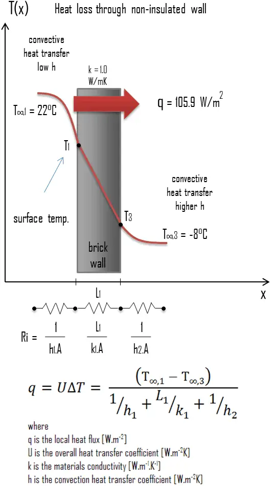
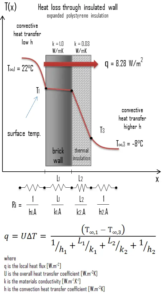
heat loss through wall - example - calculationA major source of heat loss from a house is through walls. Calculate the rate of heat flux through a wall 3 m x 10 m in area (A = 30 m2). The wall is 15 cm thick (L1) and it is made of bricks with the thermal conductivity of k1 = 1.0 W/m.K (poor thermal insulator). Assume that, the indoor and the outdoor temperatures are 22°C and -8°C, and the convection heat transfer coefficients on the inner and the outer sides are h1 = 10 W/m2K and h2 = 30 W/m2K, respectively. Note that, these convection coefficients strongly depend especially on ambient and interior conditions (wind, humidity, etc.).

  1. Calculate the heat flux (heat loss) through this non-insulated wall.
  2. Now assume thermal insulation on the outer side of this wall. Use expanded polystyrene insulation 10 cm thick (L2) with the thermal conductivity of k2 = 0.03 W/m.K and calculate the heat flux (heat loss) through this composite wall.

Solution:

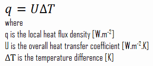
As was written, many of the heat transfer processes involve composite systems and even involve a combination of both conduction and convection. With these composite systems, it is often convenient to work with an overall heat transfer coefficient, known as a U-factor. The U-factor is defined by an expression analogous to Newton’s law of cooling:

u-factor - overall heat transfer coefficient

The overall heat transfer coefficient is related to the total thermal resistance and depends on the geometry of the problem.

  1. bare wall

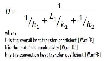
Assuming one-dimensional heat transfer through the plane wall and disregarding radiation, the overall heat transfer coefficient can be calculated as:

overall heat transfer coefficient - heat loss calculation

The overall heat transfer coefficient is then:

U = 1 / (1/10 + 0.15/1 + 1/30) = 3.53 W/m2K

The heat flux can be then calculated simply as:

q = 3.53 [W/m2K] x 30 [K] = 105.9 W/m2

The total heat loss through this wall will be:

qloss = q . A = 105.9 [W/m2] x 30 [m2] = 3177W

  1. composite wall with thermal insulation

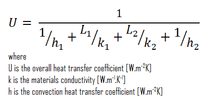
Assuming one-dimensional heat transfer through the plane composite wall, no thermal contact resistance and disregarding radiation, the overall heat transfer coefficient can be calculated as:

overall heat transfer coefficient - thermal insulation calculation

thermal insulation - expanded polystyreneThe overall heat transfer coefficient is then:

U = 1 / (1/10 + 0.15/1 + 0.1/0.03 + 1/30) = 0.276 W/m2K

The heat flux can be then calculated simply as:

q = 0.276 [W/m2K] x 30 [K] = 8.28 W/m2

The total heat loss through this wall will be:

qloss = q . A = 8.28 [W/m2] x 30 [m2] = 248 W

As can be seen, an addition of thermal insulator causes significant decrease in heat losses. It must be added, an addition of next layer of thermal insulator does not cause such high savings. This can be better seen from the thermal resistance method, which can be used to calculate the heat transfer through composite walls. The rate of steady heat transfer between two surfaces is equal to the temperature difference divided by the total thermal resistance between those two surfaces.

thermal resistance - equation

 
References:
Heat Transfer:
  1. Fundamentals of Heat and Mass Transfer, 7th Edition. Theodore L. Bergman, Adrienne S. Lavine, Frank P. Incropera. John Wiley & Sons, Incorporated, 2011. ISBN: 9781118137253.
  2. Heat and Mass Transfer. Yunus A. Cengel. McGraw-Hill Education, 2011. ISBN: 9780071077866.
  3. U.S. Department of Energy, Thermodynamics, Heat Transfer and Fluid Flow. DOE Fundamentals Handbook, Volume 2 of 3. May 2016.

Nuclear and Reactor Physics:

  1. J. R. Lamarsh, Introduction to Nuclear Reactor Theory, 2nd ed., Addison-Wesley, Reading, MA (1983).
  2. J. R. Lamarsh, A. J. Baratta, Introduction to Nuclear Engineering, 3d ed., Prentice-Hall, 2001, ISBN: 0-201-82498-1.
  3. W. M. Stacey, Nuclear Reactor Physics, John Wiley & Sons, 2001, ISBN: 0- 471-39127-1.
  4. Glasstone, Sesonske. Nuclear Reactor Engineering: Reactor Systems Engineering, Springer; 4th edition, 1994, ISBN: 978-0412985317
  5. W.S.C. Williams. Nuclear and Particle Physics. Clarendon Press; 1 edition, 1991, ISBN: 978-0198520467
  6. G.R.Keepin. Physics of Nuclear Kinetics. Addison-Wesley Pub. Co; 1st edition, 1965
  7. Robert Reed Burn, Introduction to Nuclear Reactor Operation, 1988.
  8. U.S. Department of Energy, Nuclear Physics and Reactor Theory. DOE Fundamentals Handbook, Volume 1 and 2. January 1993.
  9. Paul Reuss, Neutron Physics. EDP Sciences, 2008. ISBN: 978-2759800414.

Advanced Reactor Physics:

  1. K. O. Ott, W. A. Bezella, Introductory Nuclear Reactor Statics, American Nuclear Society, Revised edition (1989), 1989, ISBN: 0-894-48033-2.
  2. K. O. Ott, R. J. Neuhold, Introductory Nuclear Reactor Dynamics, American Nuclear Society, 1985, ISBN: 0-894-48029-4.
  3. D. L. Hetrick, Dynamics of Nuclear Reactors, American Nuclear Society, 1993, ISBN: 0-894-48453-2.
  4. E. E. Lewis, W. F. Miller, Computational Methods of Neutron Transport, American Nuclear Society, 1993, ISBN: 0-894-48452-4.

See also:

Heat Losses

We hope, this article, Facade Insulation – External Wall Insulation, helps you. If so, give us a like in the sidebar. Main purpose of this website is to help the public to learn some interesting and important information about thermal engineering.

What is Attic Insulation – Roof Insulation – Definition

Attic insulation (roof insulation) is a thermally insulated, protective interior cladding procedure involving the use of various insulation materials. Thermal Engineering

Attic Insulation – Roof Insulation

Roof - Attic - Insulation - Glass woolA very important source of heat loss from a house is through roof and attic. Attic insulation is a thermally insulated, protective interior cladding procedure involving the use of glass or rock wool, polyurethane foam or phenolic foam. It must be noted, there is a difference between insulating a pitched roof and a flat roof, and there is a difference between cold or warm loft insulation. A cold roof insulation requires insulation at joist level to stop heat escaping through the unused roof space. A warm roof is insulated between and under the rafters of the roof itself.

The purpose of roof insulation is to reduce the overall heat transfer coefficient by adding materials with low thermal conductivity.  Roof and attic insulation in buildings is an important factor to achieving thermal comfort for its occupants. Roof insulation as well as other types of insulation reduce unwanted heat loss and also reduce unwanted heat gain. They can significantly decrease the energy demands of heating and cooling systems. It must be added, there is no material which can completely prevent heat losses, heat losses can be only minimized.

Blown-In and Loose-Fill Insulation

Loose-fill materials can be blown into attics and finished wall cavities. For existing buildings that were not built with insulated cavities, a fibrous material such as cellulose insulation or glass wool is blown into the cavity through suitably drilled holes until it fills the entire wall space. Loose-fill insulation consists of small particles of fiber, foam, or other materials. The most common types of materials used for loose-fill insulation include cellulose, glass wool, and rock wool.

  • Cellulose insulation is made from recycled paper products, primarily newspapers and has a very high recycled material content.
  • Glass wool (originally known also as fiberglass) is an insulating material made from fibres of glass arranged using a binder into a texture similar to wool.
  • Stone wool, also known as rock wool, is based on natural minerals present in large quantities throughout the earth, e.g. volcanic rock, typically basalt or dolomite.

These small particles made from these materials form an insulation material that can conform to any space without disturbing structures or finishes. One of methods is Wet-spray cellulose insulation. This type insulation is similar to loose-fill insulation, but is applied with a small quantity of water to help the cellulose bind to the inside of open wall cavities.

Spray Foam Insulation

Spray foam insulation is a type of insulation that is sprayed in place through a gun. Spray foam insulation can be blown into walls, onto concrete slabs, on attic surfaces, or under floors to insulate and reduce air leakage. Spray foam can fill even the smallest cavities, creating an effective air barrier. Foam usually expands up to 30-60 times its liquid volume after it is sprayed in place. It provides excellent resistance to air infiltration (unlike batts and blankets, which can leave bypasses and air pockets, and superior to some types of loose-fill). On the other han, the cost of spray foam insulation can be higher compared to traditional insulation and most foams, with the exception of cementitious foams, release toxic fumes when they burn.

There are two types of spray foam insulation:

  • Closed-cell foam. Closed-cell foams are better insulators. Their high-density cells are closed and filled with a gas that helps the foam expand to fill the spaces around it. Closed-cell foam is very strong, and structurally reinforces the insulated surface.
  • Open-cell foam. Open-cell foam cells are not as dense and are filled with air, which gives the insulation a spongy texture. Open-cell foam is porous, allowing water vapor and liquid water to penetrate the insulation. On the other hand, open-cell foams will allow structural wood to breathe and they are about twice effective as a sound barrier.

Available foam insulation materials include:

Most are typically made with polyurethane or isocyanate. Cementitious foams are similar and can be applied in a similar manner but do not expand. These foams have higher fire resistance in comparison to polyurethane or isocyanate foams.

Insulation Materials

Thermal Insulators - ParametersAs was written, thermal insulation is based on the use of substances with very low thermal conductivity. These materials are known as insulation materials. Common insulation materials are wool, fiberglass, rock wool, polystyrene, polyurethane, and goose feather etc. These materials are very poor conductors of heat and are therefore good thermal insulators.

It must be added, thermal insulation is primarily based on the very low thermal conductivity of gases. Gases possess poor thermal conduction properties compared to liquids and solids, and thus makes a good insulation material if they can be trapped (e.g. in a foam-like structure). Air and other gases are generally good insulators. But the main benefit is in the absence of convection. Therefore, many insulation materials (e.g.polystyrene) function simply by having a large number of gas-filled pockets which prevent large-scale convection. In all types of thermal insulation, evacuation of the air in the void space will further reduce the overall thermal conductivity of the insulator.

Alternation of gas pocket and solid material causes that the heat must be transferred through many interfaces causing rapid decrease in heat transfer coefficient.

For insulation materials, three general categories can be defined. These categories are based on the chemical composition of the base material from which the insulating material is produced.

Insulation Materials - Types

In further reading, there is a brief description of these types of insulation materials.

Inorganic Insulation Materials

As can be seen from the figure, inorganic materials can be classified accordingly:

Organic Insulation Materials

The organic insulation materials treated in this section are all derived from a petrochemical or renewable feedstock (bio-based). Almost all of the petrochemical insulation materials are in the form of polymers. As can be see from the figure, all petrochemical insulation materials are cellular. A material is cellular when the structure of the material consists of pores or cells. On the other hand, many plants contain fibres for their strength, therefore almost all the bio-based insulation materials are fibrous (except expanded cork, which is cellular).

Organic insulation materials can be classified accordingly:

Other Insulation Materials

Example of Insulation – Glass Wool

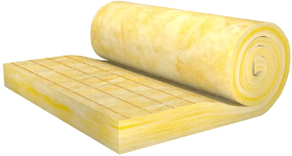
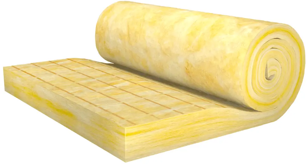
Glass wool - thermal insulationGlass wool (originally known also as fiberglass) is an insulating material made from fibres of glass arranged using a binder into a texture similar to wool. Glass wool and stone wool are produced from mineral fibres and are therefore often referred to as ‘mineral wools’. Mineral wool is a general name for fiber materials that are formed by spinning or drawing molten minerals. Glass wool is a furnace product of molten glass at a temperature of about 1450 °C. From the melted glass, fibres are spun. This process is based on spinning molten glass in high-speed spinning heads somewhat like the process used to produce cotton candy. During the spinning of the glass fibres, a binding agent is injected. Glass wool is then produced in rolls or in slabs, with different thermal and mechanical properties. It may also be produced as a material that can be sprayed or applied in place, on the surface to be insulated.

Applications of glass wool include structural insulation, pipe insulation, filtration and soundproofing. Glass wool is a versatile material that can be used for the insulation of walls, roofs and floors. It can be a loose fill material, blown into attics, or, together with an active binder sprayed on the underside of structures. During the installation of the glass wool, it should be kept dry at all times, since an increase of the moisture content causes a significant increase in thermal conductivity.

Example – Heat Loss through a Wall

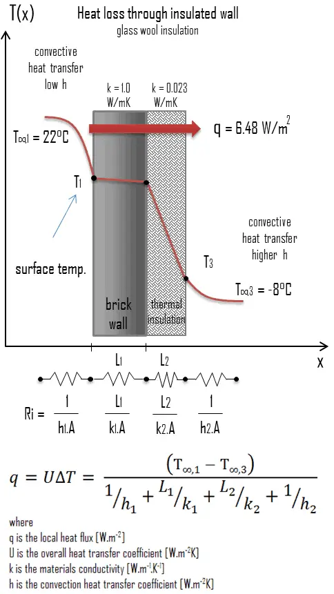
heat loss through wall - example - calculationA major source of heat loss from a house is through walls. Calculate the rate of heat flux through a wall 3 m x 10 m in area (A = 30 m2). The wall is 15 cm thick (L1) and it is made of bricks with the thermal conductivity of k1 = 1.0 W/m.K (poor thermal insulator). Assume that, the indoor and the outdoor temperatures are 22°C and -8°C, and the convection heat transfer coefficients on the inner and the outer sides are h1 = 10 W/m2K and h2 = 30 W/m2K, respectively. Note that, these convection coefficients strongly depend especially on ambient and interior conditions (wind, humidity, etc.).

  1. Calculate the heat flux (heat loss) through this non-insulated wall.
  2. Now assume thermal insulation on the outer side of this wall. Use glass wool insulation 10 cm thick (L2) with the thermal conductivity of k2 = 0.023 W/m.K and calculate the heat flux (heat loss) through this composite wall.

Solution:

As was written, many of the heat transfer processes involve composite systems and even involve a combination of both conduction and convection. With these composite systems, it is often convenient to work with an overall heat transfer coefficient, known as a U-factor. The U-factor is defined by an expression analogous to Newton’s law of cooling:

u-factor - overall heat transfer coefficient

The overall heat transfer coefficient is related to the total thermal resistance and depends on the geometry of the problem.

  1. bare wall

Assuming one-dimensional heat transfer through the plane wall and disregarding radiation, the overall heat transfer coefficient can be calculated as:

overall heat transfer coefficient - heat loss calculation

The overall heat transfer coefficient is then:

U = 1 / (1/10 + 0.15/1 + 1/30) = 3.53 W/m2K

The heat flux can be then calculated simply as:

q = 3.53 [W/m2K] x 30 [K] = 105.9 W/m2

The total heat loss through this wall will be:

qloss = q . A = 105.9 [W/m2] x 30 [m2] = 3177W

  1. composite wall with thermal insulation

Assuming one-dimensional heat transfer through the plane composite wall, no thermal contact resistance and disregarding radiation, the overall heat transfer coefficient can be calculated as:

overall heat transfer coefficient - thermal insulation calculation

glass wool insulationThe overall heat transfer coefficient is then:

U = 1 / (1/10 + 0.15/1 + 0.1/0.023 + 1/30) = 0.216 W/m2K

The heat flux can be then calculated simply as:

q = 0.216 [W/m2K] x 30 [K] = 6.48 W/m2

The total heat loss through this wall will be:

qloss = q . A = 6.48 [W/m2] x 30 [m2] = 194 W

As can be seen, an addition of thermal insulator causes significant decrease in heat losses. It must be added, an addition of next layer of thermal insulator does not cause such high savings. This can be better seen from the thermal resistance method, which can be used to calculate the heat transfer through composite walls. The rate of steady heat transfer between two surfaces is equal to the temperature difference divided by the total thermal resistance between those two surfaces.

thermal resistance - equation

 
References:
Heat Transfer:
  1. Fundamentals of Heat and Mass Transfer, 7th Edition. Theodore L. Bergman, Adrienne S. Lavine, Frank P. Incropera. John Wiley & Sons, Incorporated, 2011. ISBN: 9781118137253.
  2. Heat and Mass Transfer. Yunus A. Cengel. McGraw-Hill Education, 2011. ISBN: 9780071077866.
  3. U.S. Department of Energy, Thermodynamics, Heat Transfer and Fluid Flow. DOE Fundamentals Handbook, Volume 2 of 3. May 2016.

Nuclear and Reactor Physics:

  1. J. R. Lamarsh, Introduction to Nuclear Reactor Theory, 2nd ed., Addison-Wesley, Reading, MA (1983).
  2. J. R. Lamarsh, A. J. Baratta, Introduction to Nuclear Engineering, 3d ed., Prentice-Hall, 2001, ISBN: 0-201-82498-1.
  3. W. M. Stacey, Nuclear Reactor Physics, John Wiley & Sons, 2001, ISBN: 0- 471-39127-1.
  4. Glasstone, Sesonske. Nuclear Reactor Engineering: Reactor Systems Engineering, Springer; 4th edition, 1994, ISBN: 978-0412985317
  5. W.S.C. Williams. Nuclear and Particle Physics. Clarendon Press; 1 edition, 1991, ISBN: 978-0198520467
  6. G.R.Keepin. Physics of Nuclear Kinetics. Addison-Wesley Pub. Co; 1st edition, 1965
  7. Robert Reed Burn, Introduction to Nuclear Reactor Operation, 1988.
  8. U.S. Department of Energy, Nuclear Physics and Reactor Theory. DOE Fundamentals Handbook, Volume 1 and 2. January 1993.
  9. Paul Reuss, Neutron Physics. EDP Sciences, 2008. ISBN: 978-2759800414.

Advanced Reactor Physics:

  1. K. O. Ott, W. A. Bezella, Introductory Nuclear Reactor Statics, American Nuclear Society, Revised edition (1989), 1989, ISBN: 0-894-48033-2.
  2. K. O. Ott, R. J. Neuhold, Introductory Nuclear Reactor Dynamics, American Nuclear Society, 1985, ISBN: 0-894-48029-4.
  3. D. L. Hetrick, Dynamics of Nuclear Reactors, American Nuclear Society, 1993, ISBN: 0-894-48453-2.
  4. E. E. Lewis, W. F. Miller, Computational Methods of Neutron Transport, American Nuclear Society, 1993, ISBN: 0-894-48452-4.

See also:

Heat Losses

We hope, this article, Attic Insulation – Roof Insulation, helps you. If so, give us a like in the sidebar. Main purpose of this website is to help the public to learn some interesting and important information about thermal engineering.

What is Blown-In and Loose-Fill Insulation – Definition

Blown-In and Loose-Fill Insulation. Loose-fill insulation consists of small particles of fiber, foam, or other materials. Thermal Engineering

Blown-In and Loose-Fill Insulation

Loose-fill materials can be blown into attics and finished wall cavities. For existing buildings that were not built with insulated cavities, a fibrous material such as cellulose insulation or glass wool is blown into the cavity through suitably drilled holes until it fills the entire wall space. Loose-fill insulation consists of small particles of fiber, foam, or other materials. The most common types of materials used for loose-fill insulation include cellulose, glass wool, and rock wool.

  • Cellulose insulation is made from recycled paper products, primarily newspapers and has a very high recycled material content.
  • Glass wool (originally known also as fiberglass) is an insulating material made from fibres of glass arranged using a binder into a texture similar to wool.
  • Stone wool, also known as rock wool, is based on natural minerals present in large quantities throughout the earth, e.g. volcanic rock, typically basalt or dolomite.

These small particles made from these materials form an insulation material that can conform to any space without disturbing structures or finishes. One of methods is Wet-spray cellulose insulation. This type insulation is similar to loose-fill insulation, but is applied with a small quantity of water to help the cellulose bind to the inside of open wall cavities.

Attic Insulation – Roof Insulation

Roof - Attic - Insulation - Glass woolA very important source of heat loss from a house is through roof and attic. Attic insulation is a thermally insulated, protective interior cladding procedure involving the use of glass or rock wool, polyurethane foam or phenolic foam. It must be noted, there is a difference between insulating a pitched roof and a flat roof, and there is a difference between cold or warm loft insulation. A cold roof insulation requires insulation at joist level to stop heat escaping through the unused roof space. A warm roof is insulated between and under the rafters of the roof itself.

The purpose of roof insulation is to reduce the overall heat transfer coefficient by adding materials with low thermal conductivity.  Roof and attic insulation in buildings is an important factor to achieving thermal comfort for its occupants. Roof insulation as well as other types of insulation reduce unwanted heat loss and also reduce unwanted heat gain. They can significantly decrease the energy demands of heating and cooling systems. It must be added, there is no material which can completely prevent heat losses, heat losses can be only minimized.

Example of Insulation – Cellulose Insulation

Cellulose insulation is made from recycled paper products, primarily newspapers and has a very high recycled material content. The obtained cellulose fibres have a wool like structure (therefore paper wool). In order to make the cellulose fibres moisture and flame retardant, boric acid or ammonium sulfate are added. Cellulose insulation is used in wall and roof cavities to insulate, draught proof and reduce free noise. Cellulose insulation is used in both new and existing homes, usually as loose-fill in open attic installations and dense packed in building cavities. Cellulose and the other loose-fill materials can be blown into attics, finished wall cavities, and hard-to-reach areas.

Example – Heat Loss through a Wall

heat loss through wall - example - calculationA major source of heat loss from a house is through walls. Calculate the rate of heat flux through a wall 3 m x 10 m in area (A = 30 m2). The wall is 15 cm thick (L1) and it is made of bricks with the thermal conductivity of k1 = 1.0 W/m.K (poor thermal insulator). Assume that, the indoor and the outdoor temperatures are 22°C and -8°C, and the convection heat transfer coefficients on the inner and the outer sides are h1 = 10 W/m2K and h2 = 30 W/m2K, respectively. Note that, these convection coefficients strongly depend especially on ambient and interior conditions (wind, humidity, etc.).

  1. Calculate the heat flux (heat loss) through this non-insulated wall.
  2. Now assume thermal insulation on the outer side of this wall. Use glass wool insulation 10 cm thick (L2) with the thermal conductivity of k2 = 0.023 W/m.K and calculate the heat flux (heat loss) through this composite wall.

Solution:

As was written, many of the heat transfer processes involve composite systems and even involve a combination of both conduction and convection. With these composite systems, it is often convenient to work with an overall heat transfer coefficient, known as a U-factor. The U-factor is defined by an expression analogous to Newton’s law of cooling:

u-factor - overall heat transfer coefficient

The overall heat transfer coefficient is related to the total thermal resistance and depends on the geometry of the problem.

  1. bare wall

Assuming one-dimensional heat transfer through the plane wall and disregarding radiation, the overall heat transfer coefficient can be calculated as:

overall heat transfer coefficient - heat loss calculation

The overall heat transfer coefficient is then:

U = 1 / (1/10 + 0.15/1 + 1/30) = 3.53 W/m2K

The heat flux can be then calculated simply as:

q = 3.53 [W/m2K] x 30 [K] = 105.9 W/m2

The total heat loss through this wall will be:

qloss = q . A = 105.9 [W/m2] x 30 [m2] = 3177W

  1. composite wall with thermal insulation

Assuming one-dimensional heat transfer through the plane composite wall, no thermal contact resistance and disregarding radiation, the overall heat transfer coefficient can be calculated as:

overall heat transfer coefficient - thermal insulation calculation

glass wool insulationThe overall heat transfer coefficient is then:

U = 1 / (1/10 + 0.15/1 + 0.1/0.023 + 1/30) = 0.216 W/m2K

The heat flux can be then calculated simply as:

q = 0.216 [W/m2K] x 30 [K] = 6.48 W/m2

The total heat loss through this wall will be:

qloss = q . A = 6.48 [W/m2] x 30 [m2] = 194 W

As can be seen, an addition of thermal insulator causes significant decrease in heat losses. It must be added, an addition of next layer of thermal insulator does not cause such high savings. This can be better seen from the thermal resistance method, which can be used to calculate the heat transfer through composite walls. The rate of steady heat transfer between two surfaces is equal to the temperature difference divided by the total thermal resistance between those two surfaces.

thermal resistance - equation

 
References:
Heat Transfer:
  1. Fundamentals of Heat and Mass Transfer, 7th Edition. Theodore L. Bergman, Adrienne S. Lavine, Frank P. Incropera. John Wiley & Sons, Incorporated, 2011. ISBN: 9781118137253.
  2. Heat and Mass Transfer. Yunus A. Cengel. McGraw-Hill Education, 2011. ISBN: 9780071077866.
  3. U.S. Department of Energy, Thermodynamics, Heat Transfer and Fluid Flow. DOE Fundamentals Handbook, Volume 2 of 3. May 2016.

Nuclear and Reactor Physics:

  1. J. R. Lamarsh, Introduction to Nuclear Reactor Theory, 2nd ed., Addison-Wesley, Reading, MA (1983).
  2. J. R. Lamarsh, A. J. Baratta, Introduction to Nuclear Engineering, 3d ed., Prentice-Hall, 2001, ISBN: 0-201-82498-1.
  3. W. M. Stacey, Nuclear Reactor Physics, John Wiley & Sons, 2001, ISBN: 0- 471-39127-1.
  4. Glasstone, Sesonske. Nuclear Reactor Engineering: Reactor Systems Engineering, Springer; 4th edition, 1994, ISBN: 978-0412985317
  5. W.S.C. Williams. Nuclear and Particle Physics. Clarendon Press; 1 edition, 1991, ISBN: 978-0198520467
  6. G.R.Keepin. Physics of Nuclear Kinetics. Addison-Wesley Pub. Co; 1st edition, 1965
  7. Robert Reed Burn, Introduction to Nuclear Reactor Operation, 1988.
  8. U.S. Department of Energy, Nuclear Physics and Reactor Theory. DOE Fundamentals Handbook, Volume 1 and 2. January 1993.
  9. Paul Reuss, Neutron Physics. EDP Sciences, 2008. ISBN: 978-2759800414.

Advanced Reactor Physics:

  1. K. O. Ott, W. A. Bezella, Introductory Nuclear Reactor Statics, American Nuclear Society, Revised edition (1989), 1989, ISBN: 0-894-48033-2.
  2. K. O. Ott, R. J. Neuhold, Introductory Nuclear Reactor Dynamics, American Nuclear Society, 1985, ISBN: 0-894-48029-4.
  3. D. L. Hetrick, Dynamics of Nuclear Reactors, American Nuclear Society, 1993, ISBN: 0-894-48453-2.
  4. E. E. Lewis, W. F. Miller, Computational Methods of Neutron Transport, American Nuclear Society, 1993, ISBN: 0-894-48452-4.

See also:

Heat Losses

We hope, this article, Blown-In and Loose-Fill Insulation, helps you. If so, give us a like in the sidebar. Main purpose of this website is to help the public to learn some interesting and important information about thermal engineering.

What is Spray Foam Insulation – Definition

Spray foam insulation is a type of insulation that is sprayed in place through a gun. Spray foam insulation can be blown into walls, onto concrete slabs, on attic surfaces. Thermal Engineering

Spray Foam Insulation

Spray foam insulation is a type of insulation that is sprayed in place through a gun. Spray foam insulation can be blown into walls, onto concrete slabs, on attic surfaces, or under floors to insulate and reduce air leakage. Spray foam can fill even the smallest cavities, creating an effective air barrier. Foam usually expands up to 30-60 times its liquid volume after it is sprayed in place. It provides excellent resistance to air infiltration (unlike batts and blankets, which can leave bypasses and air pockets, and superior to some types of loose-fill). On the other han, the cost of spray foam insulation can be higher compared to traditional insulation and most foams, with the exception of cementitious foams, release toxic fumes when they burn.

There are two types of spray foam insulation:

  • Closed-cell foam. Closed-cell foams are better insulators. Their high-density cells are closed and filled with a gas that helps the foam expand to fill the spaces around it. Closed-cell foam is very strong, and structurally reinforces the insulated surface.
  • Open-cell foam. Open-cell foam cells are not as dense and are filled with air, which gives the insulation a spongy texture. Open-cell foam is porous, allowing water vapor and liquid water to penetrate the insulation. On the other hand, open-cell foams will allow structural wood to breathe and they are about twice effective as a sound barrier.

Available foam insulation materials include:

Most are typically made with polyurethane or isocyanate. Cementitious foams are similar and can be applied in a similar manner but do not expand. These foams have higher fire resistance in comparison to polyurethane or isocyanate foams.

Attic Insulation – Roof Insulation

Polyurethane foam - thermal insulationA very important source of heat loss from a house is through roof and attic. Attic insulation is a thermally insulated, protective interior cladding procedure involving the use of glass or rock wool, polyurethane foam or phenolic foam. It must be noted, there is a difference between insulating a pitched roof and a flat roof, and there is a difference between cold or warm loft insulation. A cold roof insulation requires insulation at joist level to stop heat escaping through the unused roof space. A warm roof is insulated between and under the rafters of the roof itself.

The purpose of roof insulation is to reduce the overall heat transfer coefficient by adding materials with low thermal conductivity.  Roof and attic insulation in buildings is an important factor to achieving thermal comfort for its occupants. Roof insulation as well as other types of insulation reduce unwanted heat loss and also reduce unwanted heat gain. They can significantly decrease the energy demands of heating and cooling systems. It must be added, there is no material which can completely prevent heat losses, heat losses can be only minimized.

Example of Insulation – Polyurethane Foam

Polyurethane foam (PUR) is a closed cell thermoset polymer. Polyurethane polymers are traditionally and most commonly formed by reacting a di- or poly-isocyanate with a polyol. Polyurethane foam insulation is available in closed-cell and open-cell formulas. Polyurethane foam can be used as cavity wall insulation or as roof insulation, floor insulation, pipe insulation, insulation of industrial installations. Insulating panels made from PUR can be applied to all elements of the building envelope. Another important aspect is that PUR can also be injected into existing cavity walls, by using the existing openings and some extra holes.

Example – Heat Loss through a Wall

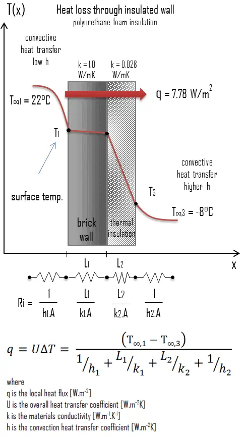
heat loss through wall - example - calculationA major source of heat loss from a house is through walls. Calculate the rate of heat flux through a wall 3 m x 10 m in area (A = 30 m2). The wall is 15 cm thick (L1) and it is made of bricks with the thermal conductivity of k1 = 1.0 W/m.K (poor thermal insulator). Assume that, the indoor and the outdoor temperatures are 22°C and -8°C, and the convection heat transfer coefficients on the inner and the outer sides are h1 = 10 W/m2K and h2 = 30 W/m2K, respectively. Note that, these convection coefficients strongly depend especially on ambient and interior conditions (wind, humidity, etc.).

  1. Calculate the heat flux (heat loss) through this non-insulated wall.
  2. Now assume thermal insulation on the outer side of this wall. Use polyurethane foam insulation 10 cm thick (L2) with the thermal conductivity of k2 = 0.028 W/m.K and calculate the heat flux (heat loss) through this composite wall.

Solution:

As was written, many of the heat transfer processes involve composite systems and even involve a combination of both conduction and convection. With these composite systems, it is often convenient to work with an overall heat transfer coefficient, known as a U-factor. The U-factor is defined by an expression analogous to Newton’s law of cooling:

u-factor - overall heat transfer coefficient

The overall heat transfer coefficient is related to the total thermal resistance and depends on the geometry of the problem.

  1. bare wall

Assuming one-dimensional heat transfer through the plane wall and disregarding radiation, the overall heat transfer coefficient can be calculated as:

overall heat transfer coefficient - heat loss calculation

The overall heat transfer coefficient is then:

U = 1 / (1/10 + 0.15/1 + 1/30) = 3.53 W/m2K

The heat flux can be then calculated simply as:

q = 3.53 [W/m2K] x 30 [K] = 105.9 W/m2

The total heat loss through this wall will be:

qloss = q . A = 105.9 [W/m2] x 30 [m2] = 3177W

  1. composite wall with thermal insulation

Assuming one-dimensional heat transfer through the plane composite wall, no thermal contact resistance and disregarding radiation, the overall heat transfer coefficient can be calculated as:

overall heat transfer coefficient - thermal insulation calculation

polyurethane foam insulationThe overall heat transfer coefficient is then:

U = 1 / (1/10 + 0.15/1 + 0.1/0.028 + 1/30) = 0.259 W/m2K

The heat flux can be then calculated simply as:

q = 0.259 [W/m2K] x 30 [K] = 7.78 W/m2

The total heat loss through this wall will be:

qloss = q . A = 7.78 [W/m2] x 30 [m2] = 233 W

As can be seen, an addition of thermal insulator causes significant decrease in heat losses. It must be added, an addition of next layer of thermal insulator does not cause such high savings. This can be better seen from the thermal resistance method, which can be used to calculate the heat transfer through composite walls. The rate of steady heat transfer between two surfaces is equal to the temperature difference divided by the total thermal resistancebetween those two surfaces.

thermal resistance - equation

 
References:
Heat Transfer:
  1. Fundamentals of Heat and Mass Transfer, 7th Edition. Theodore L. Bergman, Adrienne S. Lavine, Frank P. Incropera. John Wiley & Sons, Incorporated, 2011. ISBN: 9781118137253.
  2. Heat and Mass Transfer. Yunus A. Cengel. McGraw-Hill Education, 2011. ISBN: 9780071077866.
  3. U.S. Department of Energy, Thermodynamics, Heat Transfer and Fluid Flow. DOE Fundamentals Handbook, Volume 2 of 3. May 2016.

Nuclear and Reactor Physics:

  1. J. R. Lamarsh, Introduction to Nuclear Reactor Theory, 2nd ed., Addison-Wesley, Reading, MA (1983).
  2. J. R. Lamarsh, A. J. Baratta, Introduction to Nuclear Engineering, 3d ed., Prentice-Hall, 2001, ISBN: 0-201-82498-1.
  3. W. M. Stacey, Nuclear Reactor Physics, John Wiley & Sons, 2001, ISBN: 0- 471-39127-1.
  4. Glasstone, Sesonske. Nuclear Reactor Engineering: Reactor Systems Engineering, Springer; 4th edition, 1994, ISBN: 978-0412985317
  5. W.S.C. Williams. Nuclear and Particle Physics. Clarendon Press; 1 edition, 1991, ISBN: 978-0198520467
  6. G.R.Keepin. Physics of Nuclear Kinetics. Addison-Wesley Pub. Co; 1st edition, 1965
  7. Robert Reed Burn, Introduction to Nuclear Reactor Operation, 1988.
  8. U.S. Department of Energy, Nuclear Physics and Reactor Theory. DOE Fundamentals Handbook, Volume 1 and 2. January 1993.
  9. Paul Reuss, Neutron Physics. EDP Sciences, 2008. ISBN: 978-2759800414.

Advanced Reactor Physics:

  1. K. O. Ott, W. A. Bezella, Introductory Nuclear Reactor Statics, American Nuclear Society, Revised edition (1989), 1989, ISBN: 0-894-48033-2.
  2. K. O. Ott, R. J. Neuhold, Introductory Nuclear Reactor Dynamics, American Nuclear Society, 1985, ISBN: 0-894-48029-4.
  3. D. L. Hetrick, Dynamics of Nuclear Reactors, American Nuclear Society, 1993, ISBN: 0-894-48453-2.
  4. E. E. Lewis, W. F. Miller, Computational Methods of Neutron Transport, American Nuclear Society, 1993, ISBN: 0-894-48452-4.

See also:

Heat Losses

We hope, this article, Spray Foam Insulation, helps you. If so, give us a like in the sidebar. Main purpose of this website is to help the public to learn some interesting and important information about thermal engineering.

What is Fiberglass Insulation – Definition

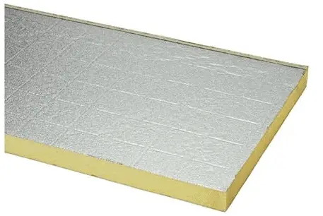
Fiberglass insulation consists of extremely fine glass fibers. It is one of the most ubiquitous insulation materials. It’s commonly used in three different types of insulation.

Fiberglass Insulation

Fiberglass insulation consists of extremely fine glass fibers. It is one of the most ubiquitous insulation materials. It’s commonly used in three different types of insulation:

  • blanket (batts and rolls)
  • loose-fill
  • rigid boards

Blown-In and Loose-Fill Insulation

Loose-fill materials can be blown into attics and finished wall cavities. For existing buildings that were not built with insulated cavities, a fibrous material such as cellulose insulation or glass wool is blown into the cavity through suitably drilled holes until it fills the entire wall space. Loose-fill insulation consists of small particles of fiber, foam, or other materials. The most common types of materials used for loose-fill insulation include cellulose, glass wool, and rock wool.

  • Cellulose insulation is made from recycled paper products, primarily newspapers and has a very high recycled material content.
  • Glass wool (originally known also as fiberglass) is an insulating material made from fibres of glass arranged using a binder into a texture similar to wool.
  • Stone wool, also known as rock wool, is based on natural minerals present in large quantities throughout the earth, e.g. volcanic rock, typically basalt or dolomite.

These small particles made from these materials form an insulation material that can conform to any space without disturbing structures or finishes. One of methods is Wet-spray cellulose insulation. This type insulation is similar to loose-fill insulation, but is applied with a small quantity of water to help the cellulose bind to the inside of open wall cavities.

Example of Insulation – Glass Wool

Roof - Attic - Insulation - Glass woolGlass wool (originally known also as fiberglass) is an insulating material made from fibres of glass arranged using a binder into a texture similar to wool. Glass wool and stone wool are produced from mineral fibres and are therefore often referred to as ‘mineral wools’. Mineral wool is a general name for fiber materials that are formed by spinning or drawing molten minerals. Glass woolis a furnace product of molten glass at a temperature of about 1450 °C. From the melted glass, fibres are spun. This process is based on spinning molten glass in high-speed spinning heads somewhat like the process used to produce cotton candy. During the spinning of the glass fibres, a binding agent is injected. Glass wool is then produced in rolls or in slabs, with different thermal and mechanical properties. It may also be produced as a material that can be sprayed or applied in place, on the surface to be insulated.

Applications of glass wool include structural insulation, pipe insulation, filtration and soundproofing. Glass wool is a versatile material that can be used for the insulation of walls, roofs and floors. It can be a loose fill material, blown into attics, or, together with an active binder sprayed on the underside of structures. During the installation of the glass wool, it should be kept dry at all times, since an increase of the moisture content causes a significant increase in thermal conductivity.

Example – Heat Loss through a Wall

heat loss through wall - example - calculationA major source of heat loss from a house is through walls. Calculate the rate of heat flux through a wall 3 m x 10 m in area (A = 30 m2). The wall is 15 cm thick (L1) and it is made of bricks with the thermal conductivity of k1 = 1.0 W/m.K (poor thermal insulator). Assume that, the indoor and the outdoor temperatures are 22°C and -8°C, and the convection heat transfer coefficients on the inner and the outer sides are h1 = 10 W/m2K and h2 = 30 W/m2K, respectively. Note that, these convection coefficients strongly depend especially on ambient and interior conditions (wind, humidity, etc.).

  1. Calculate the heat flux (heat loss) through this non-insulated wall.
  2. Now assume thermal insulation on the outer side of this wall. Use glass wool insulation 10 cm thick (L2) with the thermal conductivity of k2 = 0.023 W/m.K and calculate the heat flux (heat loss) through this composite wall.

Solution:

As was written, many of the heat transfer processes involve composite systems and even involve a combination of both conduction and convection. With these composite systems, it is often convenient to work with an overall heat transfer coefficient, known as a U-factor. The U-factor is defined by an expression analogous to Newton’s law of cooling:

u-factor - overall heat transfer coefficient

The overall heat transfer coefficient is related to the total thermal resistance and depends on the geometry of the problem.

  1. bare wall

Assuming one-dimensional heat transfer through the plane wall and disregarding radiation, the overall heat transfer coefficient can be calculated as:

overall heat transfer coefficient - heat loss calculation

The overall heat transfer coefficient is then:

U = 1 / (1/10 + 0.15/1 + 1/30) = 3.53 W/m2K

The heat flux can be then calculated simply as:

q = 3.53 [W/m2K] x 30 [K] = 105.9 W/m2

The total heat loss through this wall will be:

qloss = q . A = 105.9 [W/m2] x 30 [m2] = 3177W

  1. composite wall with thermal insulation

Assuming one-dimensional heat transfer through the plane composite wall, no thermal contact resistance and disregarding radiation, the overall heat transfer coefficient can be calculated as:

overall heat transfer coefficient - thermal insulation calculation

glass wool insulationThe overall heat transfer coefficient is then:

U = 1 / (1/10 + 0.15/1 + 0.1/0.023 + 1/30) = 0.216 W/m2K

The heat flux can be then calculated simply as:

q = 0.216 [W/m2K] x 30 [K] = 6.48 W/m2

The total heat loss through this wall will be:

qloss = q . A = 6.48 [W/m2] x 30 [m2] = 194 W

As can be seen, an addition of thermal insulator causes significant decrease in heat losses. It must be added, an addition of next layer of thermal insulator does not cause such high savings. This can be better seen from the thermal resistance method, which can be used to calculate the heat transfer through composite walls. The rate of steady heat transfer between two surfaces is equal to the temperature difference divided by the total thermal resistance between those two surfaces.

thermal resistance - equation

 
References:
Heat Transfer:
  1. Fundamentals of Heat and Mass Transfer, 7th Edition. Theodore L. Bergman, Adrienne S. Lavine, Frank P. Incropera. John Wiley & Sons, Incorporated, 2011. ISBN: 9781118137253.
  2. Heat and Mass Transfer. Yunus A. Cengel. McGraw-Hill Education, 2011. ISBN: 9780071077866.
  3. U.S. Department of Energy, Thermodynamics, Heat Transfer and Fluid Flow. DOE Fundamentals Handbook, Volume 2 of 3. May 2016.

Nuclear and Reactor Physics:

  1. J. R. Lamarsh, Introduction to Nuclear Reactor Theory, 2nd ed., Addison-Wesley, Reading, MA (1983).
  2. J. R. Lamarsh, A. J. Baratta, Introduction to Nuclear Engineering, 3d ed., Prentice-Hall, 2001, ISBN: 0-201-82498-1.
  3. W. M. Stacey, Nuclear Reactor Physics, John Wiley & Sons, 2001, ISBN: 0- 471-39127-1.
  4. Glasstone, Sesonske. Nuclear Reactor Engineering: Reactor Systems Engineering, Springer; 4th edition, 1994, ISBN: 978-0412985317
  5. W.S.C. Williams. Nuclear and Particle Physics. Clarendon Press; 1 edition, 1991, ISBN: 978-0198520467
  6. G.R.Keepin. Physics of Nuclear Kinetics. Addison-Wesley Pub. Co; 1st edition, 1965
  7. Robert Reed Burn, Introduction to Nuclear Reactor Operation, 1988.
  8. U.S. Department of Energy, Nuclear Physics and Reactor Theory. DOE Fundamentals Handbook, Volume 1 and 2. January 1993.
  9. Paul Reuss, Neutron Physics. EDP Sciences, 2008. ISBN: 978-2759800414.

Advanced Reactor Physics:

  1. K. O. Ott, W. A. Bezella, Introductory Nuclear Reactor Statics, American Nuclear Society, Revised edition (1989), 1989, ISBN: 0-894-48033-2.
  2. K. O. Ott, R. J. Neuhold, Introductory Nuclear Reactor Dynamics, American Nuclear Society, 1985, ISBN: 0-894-48029-4.
  3. D. L. Hetrick, Dynamics of Nuclear Reactors, American Nuclear Society, 1993, ISBN: 0-894-48453-2.
  4. E. E. Lewis, W. F. Miller, Computational Methods of Neutron Transport, American Nuclear Society, 1993, ISBN: 0-894-48452-4.

See also:

Heat Losses

We hope, this article, Fiberglass Insulation, helps you. If so, give us a like in the sidebar. Main purpose of this website is to help the public to learn some interesting and important information about thermal engineering.

What is Cavity Wall Insulation – Definition

Cavity wall insulation is a thermal insulation method used to reduce heat loss through a cavity wall by filling the air space with thermal insulator. Thermal Engineering

Cavity Wall Insulation

Cavity wall insulation is a thermal insulation method used to reduce heat loss through a cavity wall by filling the air space with thermal insulator. These materials (e.g. polyurethane) function simply by having a large number of gas-filled pockets which prevent large-scale convection. Alternation of gas pocket and solid material causes that the heat must be transferred through many interfaces causing rapid decrease in heat transfer coefficient.

During construction of new buildings, cavities are often filled with glass wool or rock wool panels placed between the two leaves (sides) of the wall. Polyurethane foam (PUR) is a closed cell thermoset polymer. Polyurethane foam insulation is available in closed-cell and open-cell formulas.  Polyurethane foam can be used as cavity wall insulation or as roof insulation, floor insulation, pipe insulation, insulation of industrial installations. Insulating panels made from PUR can be applied to all elements of the building envelope. Another important aspect is that PUR can also be injected into existing cavity walls, by using the existing openings and some extra holes.

For existing buildings that were not built with insulated cavities, a fibrous material such as cellulose insulation or glass wool is blown into the cavity through suitably drilled holes until it fills the entire wall space. Loose-fill insulation consists of small particles of fiber, foam, or other materials. The most common types of materials used for loose-fill insulation include cellulose, glass wool, and rock wool.

Blown-In and Loose-Fill Insulation

Loose-fill materials can be blown into attics and finished wall cavities. For existing buildings that were not built with insulated cavities, a fibrous material such as cellulose insulation or glass wool is blown into the cavity through suitably drilled holes until it fills the entire wall space. Loose-fill insulation consists of small particles of fiber, foam, or other materials. The most common types of materials used for loose-fill insulation include cellulose, glass wool, and rock wool.

  • Cellulose insulation is made from recycled paper products, primarily newspapers and has a very high recycled material content.
  • Glass wool (originally known also as fiberglass) is an insulating material made from fibres of glass arranged using a binder into a texture similar to wool.
  • Stone wool, also known as rock wool, is based on natural minerals present in large quantities throughout the earth, e.g. volcanic rock, typically basalt or dolomite.

These small particles made from these materials form an insulation material that can conform to any space without disturbing structures or finishes. One of methods is Wet-spray cellulose insulation. This type insulation is similar to loose-fill insulation, but is applied with a small quantity of water to help the cellulose bind to the inside of open wall cavities.

Example of Insulation – Cellulose Insulation

Cellulose insulation is made from recycled paper products, primarily newspapers and has a very high recycled material content. The obtained cellulose fibres have a wool like structure (therefore paper wool). In order to make the cellulose fibres moisture and flame retardant, boric acid or ammonium sulfate are added. Cellulose insulation is used in wall and roof cavities to insulate, draught proof and reduce free noise. Cellulose insulation is used in both new and existing homes, usually as loose-fill in open attic installations and dense packed in building cavities. Cellulose and the other loose-fill materials can be blown into attics, finished wall cavities, and hard-to-reach areas.

Typical thermal conductivity values for cellulose insulation are between 0.022 and 0.035W/m∙K.

Example – Heat Loss through a Wall

heat loss through wall - example - calculationA major source of heat loss from a house is through walls. Calculate the rate of heat flux through a wall 3 m x 10 m in area (A = 30 m2). The wall is 15 cm thick (L1) and it is made of bricks with the thermal conductivity of k1 = 1.0 W/m.K (poor thermal insulator). Assume that, the indoor and the outdoor temperatures are 22°C and -8°C, and the convection heat transfer coefficients on the inner and the outer sides are h1 = 10 W/m2K and h2 = 30 W/m2K, respectively. Note that, these convection coefficients strongly depend especially on ambient and interior conditions (wind, humidity, etc.).

  1. Calculate the heat flux (heat loss) through this non-insulated wall.
  2. Now assume thermal insulation on the outer side of this wall. Use glass wool insulation 10 cm thick (L2) with the thermal conductivity of k2 = 0.023 W/m.K and calculate the heat flux (heat loss) through this composite wall.

Solution:

As was written, many of the heat transfer processes involve composite systems and even involve a combination of both conduction and convection. With these composite systems, it is often convenient to work with an overall heat transfer coefficient, known as a U-factor. The U-factor is defined by an expression analogous to Newton’s law of cooling:

u-factor - overall heat transfer coefficient

The overall heat transfer coefficient is related to the total thermal resistance and depends on the geometry of the problem.

  1. bare wall

Assuming one-dimensional heat transfer through the plane wall and disregarding radiation, the overall heat transfer coefficient can be calculated as:

overall heat transfer coefficient - heat loss calculation

The overall heat transfer coefficient is then:

U = 1 / (1/10 + 0.15/1 + 1/30) = 3.53 W/m2K

The heat flux can be then calculated simply as:

q = 3.53 [W/m2K] x 30 [K] = 105.9 W/m2

The total heat loss through this wall will be:

qloss = q . A = 105.9 [W/m2] x 30 [m2] = 3177W

  1. composite wall with thermal insulation

Assuming one-dimensional heat transfer through the plane composite wall, no thermal contact resistance and disregarding radiation, the overall heat transfer coefficient can be calculated as:

overall heat transfer coefficient - thermal insulation calculation

glass wool insulationThe overall heat transfer coefficient is then:

U = 1 / (1/10 + 0.15/1 + 0.1/0.023 + 1/30) = 0.216 W/m2K

The heat flux can be then calculated simply as:

q = 0.216 [W/m2K] x 30 [K] = 6.48 W/m2

The total heat loss through this wall will be:

qloss = q . A = 6.48 [W/m2] x 30 [m2] = 194 W

As can be seen, an addition of thermal insulator causes significant decrease in heat losses. It must be added, an addition of next layer of thermal insulator does not cause such high savings. This can be better seen from the thermal resistance method, which can be used to calculate the heat transfer through composite walls. The rate of steady heat transfer between two surfaces is equal to the temperature difference divided by the total thermal resistance between those two surfaces.

thermal resistance - equation

 
References:
Heat Transfer:
  1. Fundamentals of Heat and Mass Transfer, 7th Edition. Theodore L. Bergman, Adrienne S. Lavine, Frank P. Incropera. John Wiley & Sons, Incorporated, 2011. ISBN: 9781118137253.
  2. Heat and Mass Transfer. Yunus A. Cengel. McGraw-Hill Education, 2011. ISBN: 9780071077866.
  3. U.S. Department of Energy, Thermodynamics, Heat Transfer and Fluid Flow. DOE Fundamentals Handbook, Volume 2 of 3. May 2016.

Nuclear and Reactor Physics:

  1. J. R. Lamarsh, Introduction to Nuclear Reactor Theory, 2nd ed., Addison-Wesley, Reading, MA (1983).
  2. J. R. Lamarsh, A. J. Baratta, Introduction to Nuclear Engineering, 3d ed., Prentice-Hall, 2001, ISBN: 0-201-82498-1.
  3. W. M. Stacey, Nuclear Reactor Physics, John Wiley & Sons, 2001, ISBN: 0- 471-39127-1.
  4. Glasstone, Sesonske. Nuclear Reactor Engineering: Reactor Systems Engineering, Springer; 4th edition, 1994, ISBN: 978-0412985317
  5. W.S.C. Williams. Nuclear and Particle Physics. Clarendon Press; 1 edition, 1991, ISBN: 978-0198520467
  6. G.R.Keepin. Physics of Nuclear Kinetics. Addison-Wesley Pub. Co; 1st edition, 1965
  7. Robert Reed Burn, Introduction to Nuclear Reactor Operation, 1988.
  8. U.S. Department of Energy, Nuclear Physics and Reactor Theory. DOE Fundamentals Handbook, Volume 1 and 2. January 1993.
  9. Paul Reuss, Neutron Physics. EDP Sciences, 2008. ISBN: 978-2759800414.

Advanced Reactor Physics:

  1. K. O. Ott, W. A. Bezella, Introductory Nuclear Reactor Statics, American Nuclear Society, Revised edition (1989), 1989, ISBN: 0-894-48033-2.
  2. K. O. Ott, R. J. Neuhold, Introductory Nuclear Reactor Dynamics, American Nuclear Society, 1985, ISBN: 0-894-48029-4.
  3. D. L. Hetrick, Dynamics of Nuclear Reactors, American Nuclear Society, 1993, ISBN: 0-894-48453-2.
  4. E. E. Lewis, W. F. Miller, Computational Methods of Neutron Transport, American Nuclear Society, 1993, ISBN: 0-894-48452-4.

See also:

Heat Losses

We hope, this article, Cavity Wall Insulation, helps you. If so, give us a like in the sidebar. Main purpose of this website is to help the public to learn some interesting and important information about thermal engineering.