Facebook Instagram Youtube Twitter

VAV System | Design, HVAC Efficiency in Buildings

Explore how Variable Air Volume (VAV) systems enhance HVAC efficiency in commercial buildings by optimizing energy use and improving air quality.

VAV System | Design, HVAC Efficiency in Buildings

Understanding VAV Systems: Enhancing HVAC Efficiency in Buildings

Variable Air Volume (VAV) systems are a critical component of modern heating, ventilation, and air conditioning (HVAC) technologies used extensively in medium to large-sized commercial buildings. These systems are designed not only to provide comfort but also to optimize energy usage and maintain air quality.

Design Principles of VAV Systems

VAV systems function by varying the airflow at a constant temperature to different parts of the building. The core components of a typical VAV system include a central air handler, VAV boxes (or terminals), ductwork, and controls. The design of these systems focuses on several key aspects:

  • Air Handler: This component conditions the air to a set temperature (commonly around 55°F) and then delivers it through the ductwork.
  • VAV Boxes: Located throughout the building, typically under the floor or above the ceiling, these boxes regulate the volume of cooled or heated air sent into each space. Each box is equipped with sensors and dampers controlled by thermostats in their respective zones.
  • Ductwork: Specially designed to handle lower air volumes and maintain proper air distribution and balance.
  • Controls: Modern VAV systems are often paired with sophisticated building management systems (BMS) that provide precise control over indoor environmental conditions and allow for monitoring and adjustments based on real-time data.

HVAC Efficiency in Buildings

The introduction of VAV systems has significantly advanced HVAC efficiency in several ways:

  • Energy Savings: By providing variable airflow, these systems use less energy compared to Constant Air Volume (CAV) systems. The energy performance of VAV systems is further enhanced through the use of energy-efficient motors, such as Electronically Commutated Motors (ECM).
  • Improved Environmental Control: VAV systems allow for precise temperature and airflow control in individual zones, leading to improved occupant comfort and productivity.
  • Reduced Initial and Operating Costs: Although the initial installation cost may be higher than simpler systems, the scalable nature and energy efficiency of VAV systems often result in lower overall operating costs.
  • Enhanced Indoor Air Quality: VAV systems can be integrated with air quality sensors that modulate airflow based on the detected levels of pollutants, thus ensuring a healthier indoor environment.

Conclusion

In sum, VAV systems represent a modern solution to building HVAC needs, combining comfort with efficiency and adaptability. As buildings become smarter and energy efficiency remains a global priority, the role of VAV systems in achieving these goals continues to expand. For architects, engineers, and facility managers, understanding and effectively leveraging this technology is essential in creating sustainable and comfortable environments.

By integrating advanced control technologies and maintaining a focus on tailored air delivery, VAV systems exemplify how engineered solutions can meet complex challenges in building design and operation.

Packaged Boiler | Configuration, Quick Steam Generation

Learn about packaged boilers, their configurations, and their ability to quickly generate steam for industrial and commercial use.

Packaged Boiler | Configuration, Quick Steam Generation

Understanding Packaged Boilers: Configuration and Quick Steam Generation

Packaged boilers are industrial or commercial steam and hot water generation systems that come pre-assembled in a factory before being delivered to the site. This prepackaging ensures that the boiler can be easily and quickly installed, requiring only connections to utilities to become operational. Packaged boilers are preferred in locations where space is at a premium and where boiler room accessibility is limited.

Configurations of Packaged Boilers

Packaged boilers come in various configurations which significantly influence their operation, efficiency, and the speed at which they generate steam. The most common types of packaged boiler configurations are:

  • Fire Tube Boilers: In this configuration, the combustion gases pass inside boiler tubes, which are surrounded by the water they are meant to heat. Fire tube boilers are preferred for their simplicity and low cost.
  • Water Tube Boilers: Unlike fire tube boilers, water tube boilers have water inside the tubes that is heated by hot gases around them. These boilers are chosen for their ability to produce high-pressure steam and for their quick response to changes in steam demand.
  • Electric Boilers: These utilize electricity to generate heat and do not depend on the combustion of fuels. They are known for their clean operation and are typically used in areas where combustion in confined spaces is problematic.
  • Combination Boilers: These boilers can use more than one source of energy, for example, gas and oil, and can switch between these fuels based on availability and cost.

Quick Steam Generation Capabilities

Quick steam generation is crucial in applications where steam demands can peak suddenly, such as in processing industries or hospitals. The ability of packaged boilers to start rapidly and reach full operational capacity in a short time is a significant advantage. Several factors contribute to a boiler’s quick steam generation capabilities:

  • Boiler Design: Water tube boilers generally have faster start-up times than fire tube boilers due to their lower water volume and quicker response times.
  • Heat Transfer Efficiency: The efficiency with which heat is transferred from the combustion gas to the water has a direct impact on steam generation speed. Enhanced heat transfer design features, like turbulators in fire tubes, improve this efficiency.
  • Fuel and Combustion Efficiency: The type of fuel used and the efficiency of the combustion process also affect how quickly a boiler can generate steam. High calorific fuels and advanced combustion technologies ensure quicker heat availability.
  • Automation: Modern packaged boilers are equipped with advanced control systems that optimize combustion and heat transfer, achieving quicker response times and maintaining steady pressure and temperature as required.

Conclusion

Packaged boilers represent a highly efficient and space-saving solution in industrial and commercial steam generation. Their modular design not only simplifies installation but also enhances operational efficiency, making them an excellent choice for facilities requiring quick steam generation capabilities. As technology advances, these boilers continue to improve, offering greater efficiencies and more sophisticated options to meet diverse needs.

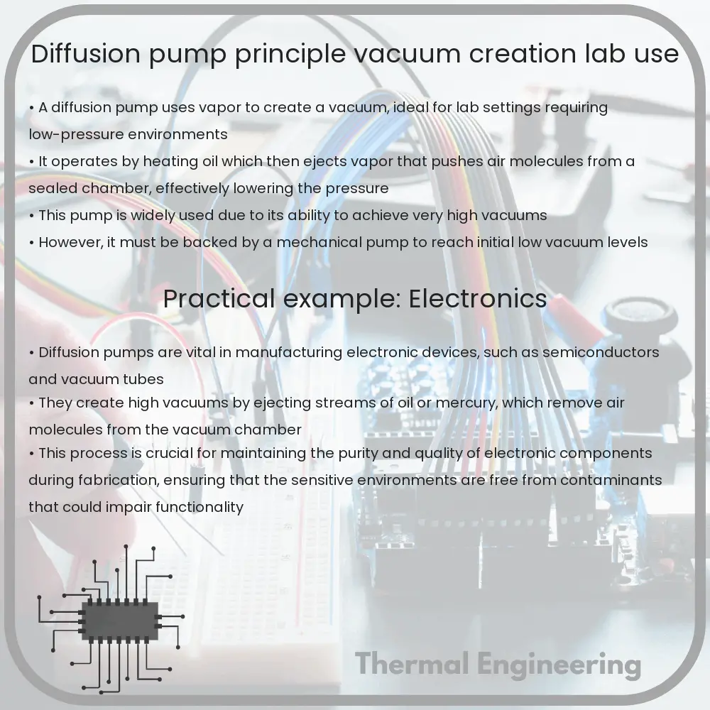
Diffusion Pump | Principle, Vacuum Creation, Lab Use

Learn how a diffusion pump operates to create high vacuums essential for scientific and industrial applications.

Diffusion Pump | Principle, Vacuum Creation, Lab Use

Understanding the Diffusion Pump

A diffusion pump is a key tool used in numerous scientific, engineering, and industrial applications where creating a high vacuum is essential. This remarkable device, which utilizes a vapor jet to transfer momentum to gas molecules, dramatically lowers the pressure within a sealed volume to create a near-perfect vacuum environment.

Principle of Operation

The core principle of a diffusion pump involves the use of a high-speed jet of vapor to entrap air molecules and direct them downwards and out of the pump, thus lowering the air pressure inside the chamber. Here’s a step-by-step breakdown of how it works:

  1. Heating the Fluid: The pump starts with heating a fluid, typically oil or mercury, to a boil. The choice of fluid depends on the operating temperature range and the desired vacuum quality.
  2. Vapor Jet Creation: As the fluid boils, it transforms into vapor. This vapor is then ejected through a nozzle positioned at the top of the pump, creating a high-speed jet.
  3. Momentum Transfer: The gas molecules in the chamber collide with the high-speed vapor molecules. Due to these collisions, the gas molecules gain momentum and are forced towards the outer walls of the pump.
  4. Capture and Removal of Gases: The outer wall of the diffusion pump is cooled, typically by a water jacket. When the vapor carrying the entrained gas molecules reaches this cooler surface, it condenses. Subsequently, the condensed fluid (along with the captured gases) drips down into the base of the pump where it’s re-heated and the process repeats.

This cycle of heating, vaporizing, momentum transfer, and condensation effectively removes air molecules from the chamber, creating a vacuum.

Vacuum Creation

The diffusion pump is capable of achieving very low pressures, often down to 10-10 Torr. This extreme vacuum is achievable because the pump continually removes air molecules from the chamber without reintroducing them—a key feature of its design that exploits thermal and momentum principles efficiently.

Applications in Laboratories

In the context of laboratory use, the diffusion pump has several critical applications:

  • Mass Spectrometry: Creating the necessary vacuum conditions for accurate mass analysis of samples.
  • Electron Microscopy: Removing air to allow electron beams to travel without interacting with gas molecules, which increases resolution and clarity.
  • Vacuum Coating: Providing the appropriate environment for the deposition of thin films via vapor deposition techniques.
  • Space Simulation: Simulating space-like vacuum conditions for testing spacecraft components and other related technologies.

The versatility of the diffusion pump in supporting such sensitive and intricate procedures underscores its importance in scientific and engineering fields. Reliable and effective, the diffusion pump remains a cornerstone technology for creating high vacuum environments.

Conclusion

The diffusion pump is an exemplary example of engineering ingenuity applied to solve practical problems in science and technology. By leveraging basic physical principles of vapor dynamics and momentum transfer, it provides a robust solution for achieving ultra-high vacuum conditions necessary for many modern scientific endeavors.

Direct Contact Heat Exchanger | Types, Process Industry Use

Learn about direct contact heat exchangers, devices that efficiently transfer heat between fluids in direct contact, widely used across various industries.

Direct Contact Heat Exchanger | Types, Process Industry Use

What is a Direct Contact Heat Exchanger?

A direct contact heat exchanger is a device where heat is transferred between two substances that are in direct contact with each other. Unlike indirect contact heat exchangers, where a solid wall separates the fluids to avoid mixing, direct contact heat exchangers allow the interacting fluids to mix freely. This immediate interaction can result in a more efficient transfer of heat.

Types of Direct Contact Heat Exchangers

  • Gas-liquid heat exchangers: Typically used in air conditioning and refrigeration, these exchangers involve the direct contact of a gas with a liquid to either absorb or release heat.
  • Liquid-liquid heat exchangers: Commonly used in chemical processes, these units facilitate heat transfer between two immiscible liquids or between miscible liquids that require rapid temperature changes.
  • Solid-liquid heat exchangers: These are used in situations like cooling of molten slag by water, where the hot solid directly contacts the cooler liquid.
  • Liquid-vapor heat exchangers: This type involves the boiling of liquid in the presence of a vapor or the condensation of a vapor upon contact with a cooler liquid.

How Direct Contact Heat Exchangers Work

In a basic operation of a direct contact heat exchanger, the warmer fluid transfers its heat to the colder fluid until the temperatures of both fluids start to equalize. Depending on the system design, the fluids can be separated after heating or cooling has occurred or can continue to remain mixed depending on the application requirements. Heat transfer in these systems often utilizes the large specific heat capacity and phase change properties of the fluids involved.

Advantages of Direct Contact Heat Exchangers

  • High Heat Transfer Coefficients: Direct contact facilitates higher heat transfer rates because the thermal resistance of a separating wall is eliminated.
  • Cost Efficiency: These systems are generally cheaper to build and operate, as they require fewer materials and less maintenance.
  • Simplicity: The design and operation mechanisms are often simpler compared to indirect heat exchangers.
  • Versatility: They are capable of handling a wide range of temperatures and pressures, and can also accommodate fluids with particles or high levels of impurities.

Applications in the Process Industry

Direct contact heat exchangers are widely used in various processing industries. For example:

  • In the petrochemical industry, they are used to cool or heat hydrocarbons during the refining process.
  • In power generation, these exchangers help in cooling the steam near the exhaust stages of turbines to condense the steam back into water.
  • Water treatment facilities use these devices for the temperature regulation of water before it is released into natural bodies or recycled.
  • The food and beverage industry applies these exchangers in processes where rapid heating or cooling is pivotal, such as in the pasteurization of milk.

Conclusion

Direct contact heat exchangers are vital components in numerous industrial applications, providing efficient and cost-effective solutions for temperature control and heat transfer. Their ability to handle a variety of fluids and operating conditions makes them an indispensable tool in the engineering field.

Magnetic Bearing | Tech, High-Speed Turbine Applications

Learn how magnetic bearings use electromagnetism to reduce friction in high-speed turbines, enhancing efficiency and reliability.

Magnetic Bearing | Tech, High-Speed Turbine Applications

Understanding Magnetic Bearings: Revolutionizing High-Speed Turbine Applications

Magnetic bearings are a key component in modern engineering, providing significant advantages over traditional mechanical bearings. By suspending objects using magnetic fields, magnetic bearings eliminate direct contact between moving parts, which reduces friction, wear, and the need for lubrication. This technology is particularly integral in the operation of high-speed turbines, which are critical in various industries such as power generation, aerospace, and high-speed transportation.

How Magnetic Bearings Work

Magnetic bearings function based on the principles of electromagnetism. Essentially, they use controlled magnetic fields to levitate and support a rotating shaft. There are two main types of magnetic bearings: Active Magnetic Bearings (AMBs) and Passive Magnetic Bearings (PMBs).

  • Active Magnetic Bearings (AMBs): AMBs employ an electronic control system that continually adjusts electromagnets to maintain the position of the rotor within the bearing. Sensors monitor the position of the rotor, and a feedback loop adjusts the magnetic force as needed. This system requires continuous power supply and sophisticated control strategies to ensure stability and precise positioning.
  • Passive Magnetic Bearings (PMBs): PMBs utilize permanent magnets and do not require external control systems or power supply. They rely on the natural repulsive or attractive forces between magnets to maintain the rotor position. However, PMBs alone are typically not sufficient to fully stabilize a system due to their inherent instability in certain directions and are often used in conjunction with other types of bearings.

Equations Governing Magnetic Bearings

The behavior of magnetic bearings can be described by Maxwell’s equations, combined with the Lorentz force law. The basic equation for the Lorentz force (FL) which acts on a moving charge in magnetic fields is:

FL = q(E + v × B)

where:

  • q is the charge of the particle,
  • E is the electric field,
  • v is the velocity of the particle, and
  • B is the magnetic field.

In magnetic bearings, the magnetic field (B) is manipulated to control the position and stability of the rotor, using feedback from position sensors.

Applications in High-Speed Turbines

High-speed turbines are one of the principal applications of magnetic bearings. These turbines often operate at speeds that can induce significant wear and tear on mechanical bearings. Some specific applications in this area include:

  1. Gas and Steam Turbines: In power plants, turbines must operate efficiently and reliably at high rotational speeds. Magnetic bearings reduce the maintenance needs and improve the efficiency by decreasing friction losses.
  2. Aerospace: In jet engines and other aerospace applications, minimizing weight and reducing maintenance requirements are vital. Magnetic bearings contribute to lighter, more efficient engine designs.
  3. High-Speed Trains: Magnetic bearings are used in the drive systems of some high-speed trains, enhancing reliability and reducing maintenance costs.

Benefits and Drawbacks

The adoption of magnetic bearings in engineering applications comes with both benefits and challenges:

  • Benefits: Increases system efficiency; reduces wear, vibration, and noise; lowers maintenance costs; and eliminates the need for lubrication, which can be particularly beneficial in vacuum or clean-room environments.
  • Drawbacks: Higher initial costs and complexity; requires sophisticated control systems and sensors; and is dependent on a continuous power supply for active magnetic bearings.

In conclusion, while magnetic bearings present some challenges, their benefits in high-speed turbine applications—especially in terms of efficiency, reliability, and environmental impact—make them a compelling choice for modern engineering solutions.

Rotary Screw Compressor | Design, Energy Use

Learn about the design, efficiency, and applications of rotary screw compressors, critical for modern industrial use.

Rotary Screw Compressor | Design, Energy Use

Introduction to Rotary Screw Compressors

A rotary screw compressor is a type of gas compressor known for its efficiency and capability to produce high pressures using a continuous sweeping motion. They are widely used in various settings such as manufacturing, construction, and air conditioning due to their reliability and durability.

Design and Principles of Operation

Rotary screw compressors consist of two main rotors: one male and one female. These rotors are meshed together and as they rotate, gas typically air gets trapped in the pockets between the screws. As the screws turn, the volume of these pockets decreases, which in turn compresses the gas.

The design differences in compressors mainly pertain to the type of rotor, which can be either lubricated or non-lubricated. Lubricated rotary screw compressors allow for higher sealing and reduced internal friction, but require ongoing maintenance to manage oil content in the discharged air. Non-lubricated compressors, while simpler and often emitting cleaner air, may have reduced efficiency and increased wear over time.

The assembly is housed in a casing which includes inlet and outlet ports uniquely designed to manage the flow of air efficiently and to optimize the compression process.

Energy Use and Efficiency

The efficiency of a rotary screw compressor is measured by its ability to convert input electric energy into compressed air effectively, while minimizing losses. The specific power (kW/m3/min) is a commonly used metric, distributing the compressor’s power consumption over its output. The lower the specific power, the more efficient the compressor.

Several factors contribute to the energy efficiency of these compressors:

  • Quality of components: High-quality components can reduce energy losses due to friction and leakage.
  • Screw design: The design and precision of the screw’s profile significantly impact performance.
  • Control systems: Modern compressors often feature advanced control systems that optimize operating speeds and reduce energy consumption during lower demand periods.

Improvements in rotary screw compressor designs continue to focus on reducing energy use. Techniques such as variable frequency drives (VFD) are used to adjust the motor speed according to the demand, significantly cutting down energy consumption and prolonging the lifespan of the compressor.

Practical Applications

Rotary screw compressors serve a vital role in many industries including:

  • Manufacturing, where they provide a reliable source of compressed air for tools and machinery.
  • Automotive industries, for operations such as painting and tool powering.
  • Construction, particularly in powering pneumatic equipment.
  • Pharmaceuticals, where oil-free air is essential for process and production environments.

The adaptability in size, design, and capability ensures that rotary screw compressors meet various demands, making them indispensable in industrial settings.

Conclusion

Rotary screw compressors are critical in modern industrial applications due to their high efficiency and robust performance. Continued innovations aimed at enhancing their energy efficiency and performance have solidified their place as a preferred option for continuous-duty compressed air production. Enabling reliable and economical operation, they significantly contribute to the productivity and operational efficiencies across multiple industries.

Thermal comfort in vehicle cabin design

Explore how vehicle cabin design optimizes thermal comfort using engineering and computational techniques to ensure a pleasant driving experience.

Thermal comfort in vehicle cabin design

Understanding Thermal Comfort in Vehicle Cabin Design

The concept of thermal comfort in vehicle cabin design is crucial for providing a pleasant driving and passenger experience. The design and engineering teams involved in automotive manufacturing focus on various aspects of thermal physics to ensure that the cabin maintains a comfortable temperature, regardless of the external weather conditions.

Factors Influencing Thermal Comfort

Thermal comfort within a vehicle is influenced by several factors:

  • Air Temperature: This is the most obvious factor and involves heating or cooling the air inside the cabin to an optimal level.
  • Humidity: Relative humidity affects how we perceive the comfort of the air around us. Systems must manage moisture content in the air to optimize comfort.
  • Air Velocity: Movement of air can enhance comfort by improving heat exchange between the body and the air.
  • Radiant Temperature: Heat radiated from surfaces within the car, like the dashboard or seats, also affects comfort levels.
  • Metabolic Rate: The heat generated by passengers’ bodies will affect the temperature inside the cabin. Each person naturally emits heat, which needs to be considered in managing the cabin’s overall climate.
  • Clothing: The type of clothes passengers wear can influence thermal comfort, affecting the heat transfer rate between the body and the surrounding air.

Engineering Solutions for Thermal Comfort

To manage and enhance thermal comfort in vehicles, engineers use a variety of technologies and design approaches:

  1. HVAC Systems: Heating, Ventilation, and Air Conditioning (HVAC) systems are designed to control the temperature, humidity, and air flow within the cabin effectively.
  2. Insulation Materials: Using advanced insulation materials in the car’s body helps maintain the desired temperature by reducing heat transfer between the inside and outside of the car.
  3. Window Design: Windows can be designed with special coatings that reflect infrared light, helping to keep the cabin cooler in hot conditions or help retain warmth during colder conditions.
  4. Seat Materials: The choice of materials for seats and their ability to conduct or insulate heat play a significant role in thermal comfort. For example, breathable fabrics and active ventilation systems in seats can help in maintaining comfort during long drives.
  5. Automated Climate Control: Advanced systems can automatically adjust the interior conditions based on sensors that detect temperature, humidity, and even occupancy.

Computational Techniques in Design

Engineers also rely on computational methods to predict and improve cabin comfort during the design phase. Computational Fluid Dynamics (CFD) is commonly used to simulate air flow inside the cabin, allowing designers to optimize HVAC systems and the placement of vents to ensure even distribution of conditioned air. Furthermore, thermal modeling can predict the contributions of various surfaces to the overall heat balance within the cabin.

Overall, thermal comfort in vehicle cabin design is a sophisticated field that combines elements of physics, material science, human physiology, and computer modeling to achieve environments that are not only comfortable but also energy-efficient. As technology progresses, the integration of smarter systems and predictive algorithms holds the promise of continuously enhancing passenger comfort and driving experiences.

Plate & Frame Filter Press | Structure, Wastewater Treatment

Learn about the Plate & Frame Filter Press, essential for solid-liquid separation in industries like wastewater treatment.

Plate & Frame Filter Press | Structure, Wastewater Treatment

Understanding the Plate & Frame Filter Press

A Plate & Frame Filter Press is a type of mechanical device widely used in various industries, including wastewater treatment, for solid-liquid separation. This equipment plays a critical role in helping facilities manage and repurpose their waste products efficiently. Here, we’ll delve into the basic structure of a Plate & Frame Filter Press and its applications in wastewater treatment.

Structure of Plate & Frame Filter Press

The fundamental components of a Plate & Frame Filter Press include the frame, filter plates, and filter cloths. These elements work together to form a series of chambers that facilitate effective filtration.

  • Frame: The frame acts as the main structural support for the filter press and holds the filter plates and cloths in place.
  • Filter Plates: These are sturdy plates typically made of polymer or stainless steel, between which the slurry (mixture of solids and liquids) is placed. Filter plates come in various shapes and sizes, depending on their intended use.
  • Filter Cloths: These are installed in between the filter plates. Made from various materials like polypropylene, the cloths act as semi-permeable barriers that allow the passage of liquid but retain solid particles.

In operation, the slurry is pumped into the press and pressure is applied to remove excess water from the solids via the filter cloths. The “cake,” or the accumulated solids between each plate, forms the primary product of this process.

Wastewater Treatment Using a Filter Press

In wastewater treatment, filter presses are instrumental for dewatering sludge. Sludge is a by-product of processes ranging from industrial to municipal wastewater treatments. The treatment of wastewater involves several stages:

  • Slurry Preparation: Wastewater containing solid waste is collected and prepared as a slurry.
  • Filtration: The slurry is fed into the filter press where pressure is applied. The liquid, which passes through the filter cloth, is collected as filtrate.
  • Solid Waste Collection: Solids form into a cake-like substance between filter plates which is then collected and disposed of or further treated.

Depending on the nature of the wastewater and the composition of the solid waste, the filter press may incorporate additives such as flocculants to improve filtration efficiency.

Applications of a Filter Press in Various Industries

While wastewater treatment is a primary application, filter presses also find extensive use in several other industries:

  • Chemical manufacturing: For separating chemicals in the production process.
  • Mining: For the dewatering of mineral processing slurry.
  • Food and beverage: For the filtration of edible oils, sugars, and other essential ingredients.

Conclusion

The Plate & Frame Filter Press is a vital component in both wastewater treatment and various industrial processes. By efficiently separating solids from liquids, it allows for the effective management of waste products and helps in adhering to environmental compliance. Understanding the structure and function of this equipment can provide insights into its critical role in industrial operations and sustainability efforts.

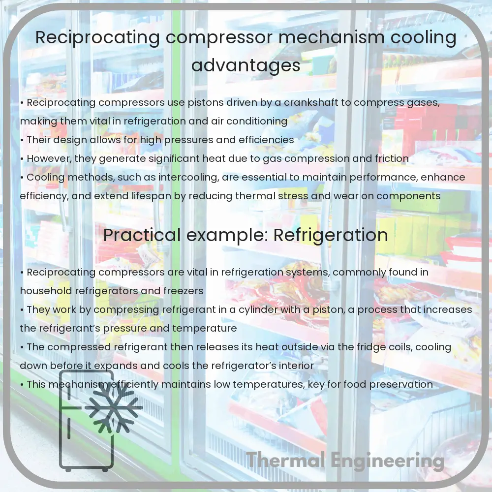
Reciprocating Compressor | Mechanism, Cooling Advantages

Learn how reciprocating compressors work, their mechanism, and the benefits of their cooling systems in industrial applications.

Reciprocating Compressor | Mechanism, Cooling Advantages

Understanding Reciprocating Compressors: Mechanism and Cooling Advantages

A reciprocating compressor is one of the most commonly used types of compressors in various industrial applications, from refrigeration to pneumatic systems. This article explores the basic operating mechanism of a reciprocating compressor and the advantages of its cooling system.

How a Reciprocating Compressor Works

The reciprocating compressor operates much like an internal combustion engine but in reverse. It includes several key components: the piston, cylinder, crankshaft, connecting rod, and valves.

  • Piston: Moves back and forth within the cylinder.
  • Cylinder: Houses the piston and the compressed air or gas.
  • Crankshaft: Converts the rotational motion into a reciprocating motion that drives the piston.
  • Connecting Rod: Connects the piston to the crankshaft, facilitating the transmission of motion.
  • Valves: Control the intake of gas into the cylinder and the exit of the compressed gas.

The basic operation of a reciprocating compressor can be summarized in three stages: intake, compression, and exhaust.

  1. Intake: The inlet valve opens, allowing the gas to fill the cylinder; the piston moves downward, reducing the pressure inside the cylinder.
  2. Compression: The inlet valve closes, and the piston moves upward, compressing the gas trapped inside the cylinder.
  3. Exhaust: The compressed gas opens the exhaust valve and is pushed out into the discharge pipe as the piston continues to move up.

The described mechanism results in increasing the pressure of the gas by decreasing its volume, following Boyle’s Law, which states that for a fixed amount of an ideal gas kept at fixed temperature, pressure and volume are inversely proportional.

Cooling Advantages of Reciprocating Compressors

Compression of gas generates heat due to the energy input and friction. Cooling in reciprocating compressors is crucial not only for maintaining efficiency but also for ensuring the safety and longevity of the system. Key cooling advantages include:

  • Reduced Risk of Overheating: Effective cooling controls the temperature rise during the compression process, preventing potential damage due to overheating.
  • Improved Efficiency: Cooling helps maintain a consistent operational temperature, ensuring that the compressor operates efficiently and the gas properties remain stable.
  • Extended Equipment Life: Lower operating temperatures reduce the wear and tear on compressor components, extending the life span of the equipment.

Reciprocating compressors typically employ one of two cooling methods:

  1. Air Cooling: Utilizes air flow generated by fans or natural convection to lower the temperature of the compressor parts.
  2. Water Cooling: Involves water jackets around the cylinder or the use of cooling towers, which transfer the compressor heat to water, significantly reducing the temperature.

Choosing the appropriate cooling method depends on various factors such as the specific application, ambient conditions, and performance requirements. In general, water cooling is more effective for larger or more intensive operations, while air cooling may suffice for smaller, less demanding environments.

Understanding the mechanism and the importance of cooling in reciprocating compressors can play a pivotal role in maximizing efficiency and durability in industrial applications. Whether used in refrigeration systems, air conditioning, or industrial pneumatic systems, these compressors are essential for reliable operation and optimal performance.

Thermal Break Windows | Construction, Energy Efficiency

Learn how thermal break windows enhance energy efficiency and comfort by reducing heat transfer and noise in modern buildings.

Thermal Break Windows | Construction, Energy Efficiency

Understanding Thermal Break Windows

Thermal break windows are a modern advancement in window technology designed to improve energy efficiency and comfort in buildings. These windows play a crucial role in both residential and commercial structures by minimizing energy loss and reducing the influx of noise.

Construction of Thermal Break Windows

Thermal break windows incorporate a barrier between the inside and outside window frames that is made of a less conductive material. This intermediary material effectively interrupts the thermal pathway through the window frame. The most common materials used for thermal breaks are polyamide, reinforced polyurethane, and other insulating polymers, which have low thermal conductivity.

  • Frames: Typically made from aluminum, which is strong and durable but has high thermal conductivity. The thermal break technology helps to overcome this disadvantage.
  • Glazing: These windows usually feature double or triple glazing, with air or inert gas (like argon or krypton) sandwiched between the panes to reduce heat transfer.
  • Seals: High-quality seals are crucial to prevent air leakage, further assisting in insulation.

Energy Efficiency of Thermal Break Windows

Thermal break windows help in maintaining consistent indoor temperatures by acting as a barrier to heat transfer. This energy efficiency is quantified through various ratings:

  • U-value: This measures how well a window can keep out heat. The lower the U-value, the better the insulation properties of the window.
  • R-value: Conversely, the R-value measures the resistance to heat flow. A higher R-value indicates better insulation and energy efficiency.

By reducing the demand on heating and cooling systems, thermal break windows lower energy consumption, leading to significant cost savings over time and a reduction in the carbon footprint of the building.

Benefits beyond Energy Efficiency

  • Enhanced Comfort: Reduces drafts and cold spots around windows.
  • Noise Reduction: The insulated glazing can markedly decrease the level of sound that enters a space from outside.
  • Reduced Condensation: Helps in limiting condensation on window surfaces, which is beneficial in preventing mold growth and maintaining indoor air quality.

Implementation of thermal break technology in windows is a practical step towards enhancing building sustainability and occupant comfort. Whether you’re renovating old structures or designing new ones, incorporating thermal break windows is considered a best practice in modern construction.

Conclusion

Thermal break windows represent a significant stride forward in building technology, allowing not only for reductions in energy bills but also offering improvements in the overall environmental sustainability of construction projects. As such, they hold an essential place in contemporary architectural design considerate of energy conservation and environmental protection.