Facebook Instagram Youtube Twitter

Centrifugal Chiller | Energy Efficiency, Mechanism

Learn about centrifugal chillers, their working mechanism, energy efficiency factors, and the latest advancements enhancing their performance.
Centrifugal Chiller | Energy Efficiency, Mechanism

Understanding Centrifugal Chillers: Mechanism and Energy Efficiency

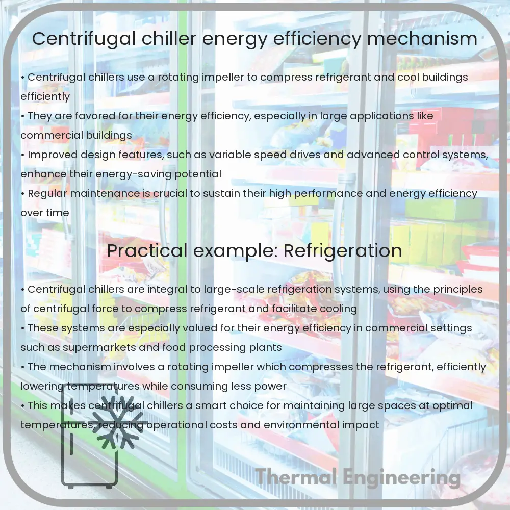
Centrifugal chillers are a fundamental component in large-scale air conditioning systems, utilized in commercial buildings, industrial facilities, and large institutions. These systems are designed to provide efficient and reliable cooling by employing the principles of vapor-compression refrigeration. Understanding the mechanism of operation and the aspects that influence the energy efficiency of centrifugal chillers can help in optimizing their performance and reducing operational costs.

How Does a Centrifugal Chiller Work?

The core operation of a centrifugal chiller revolves around the vapor-compression cycle, which consists of four main components: the evaporator, the compressor, the condenser, and the expansion valve.

  • Evaporator: The refrigerant absorbs heat from the chilled water and begins to boil, turning from a liquid into a vapor.
  • Compressor: This component, specifically a centrifugal impeller in this case, draws the refrigerant vapor from the evaporator. The impeller increases the pressure and temperature of the refrigerant by spinning it at high speed using centrifugal force.
  • Condenser: The high-pressure vapor is then cooled in the condenser where it rejects the absorbed heat to the cooling water or air outside the system.
  • Expansion Valve: The high-pressure liquid refrigerant passes through an expansion valve where it undergoes a pressure drop, cooling it down before it returns to the evaporator, completing the cycle.

Factors Affecting Energy Efficiency

The efficiency of centrifugal chillers is influenced by several factors, both mechanical and environmental. Here are some key aspects:

  • Compressor Design: The efficiency of the compressor, particularly how well it can compress the refrigerant without losing energy to friction and heat, is crucial.
  • Refrigerant Type: Different refrigerants have varying thermodynamic properties that can affect both the efficiency and environmental impact of the chiller.
  • Load Management: Chillers operate most efficiently at full load. Variable frequency drives (VFDs) can adjust the speed of the compressor, improving efficiency in part-load conditions.
  • Temperature of Condensing Water: Lower condensing water temperatures generally improve the efficiency of the chiller by reducing the work the compressor has to do.

Technological Advances in Centrifugal Chillers

Recent advancements in centrifugal chiller technology have focused on improving energy efficiency and reducing environmental impact. Examples include:

  • Magnetic Bearing Compressors: These compressors eliminate the need for oil lubrication, reducing maintenance costs and increasing efficiency by decreasing friction losses.
  • Variable-speed Drives: By adjusting the motor speed based on cooling demand, these drives can significantly reduce energy consumption.
  • Eco-friendly Refrigerants: New refrigerants with lower global warming potentials (GWPs) are being developed to replace older, more harmful chemicals.

Implementing these technologies can significantly improve the performance of centrifugal chillers, offering both economic and environmental benefits.

Conclusion

Centrifugal chillers are critical to the operation of many large-scale cooling systems. By understanding the mechanisms of these chillers, and the factors that affect their efficiency, operators can better manage their performance. Furthermore, embracing technological advancements can help in achieving higher efficiency and sustainability in cooling solutions. Such strategies are not only beneficial in reducing operational costs but also in contributing to global environmental conservation efforts.

Spiral Heat Exchanger | Compact, Efficiency

Learn about spiral heat exchangers, their design, efficiency, and applications in various industries, highlighting advantages and limitations.

Spiral Heat Exchanger | Compact, Efficiency

Understanding the Spiral Heat Exchanger

A spiral heat exchanger is a type of compact heat exchanger known for its high efficiency and ability to handle different process streams effectively. Its unique design features two long metal plates rolled around a central core to form two concentric spiral channels, one for each fluid, allowing true counter-current flow. This design maximizes heat transfer and minimizes space usage, making it ideal for applications with limited space.

Design and Construction

The construction of a spiral heat exchanger begins with the selection of materials, usually stainless steel or titanium, which provide corrosion resistance and durability. The two channels are separated by a welded or gasketed seal depending on the application’s temperature and pressure requirements. One channel is typically kept at a higher pressure than the other to prevent mixing of the fluids in case of a seal failure.

Operation Efficiency

The efficiency of spiral heat exchangers can be attributed to several factors:

  • Counter-current flow: This arrangement allows the hot and cold fluids to enter the heat exchanger from opposite ends, enhancing the temperature gradient and improving heat transfer.
  • High surface area: The spiraling layers increase the surface area available for heat transfer without requiring more ground space, boosting the efficiency per unit volume.
  • Self-cleaning mechanism: The single-channel design allows for higher flow velocities, which reduce the likelihood of fouling by flushing sediment and particles out of the system.

The effectiveness of a spiral heat exchanger can be estimated by its overall heat transfer coefficient (\(U\)), which depends on factors like material thermal conductivity, flow arrangement, and the physical properties of the fluids. The performance is also impacted by the pressure drop across the exchanger, which should be minimized to reduce energy consumption in pumping fluids.

Applications

Spiral heat exchangers are versatile and can be used in various industrial processes:

  • Chemical processing: Suitable for handling corrosive fluids, large particle suspensions, and high-temperature applications.
  • Food and beverage: Used in pasteurization processes and bulk cooling or heating of food products.
  • Wastewater treatment: Efficient in heat recovery operations and sludge cooling applications.
  • Energy sector: Applied in biomass power plants and geothermal installations for efficient heat transfer processes.

Advantages and Limitations

Spiral heat exchangers offer numerous advantages but also possess some limitations:

  • Advantages:
    • High thermal efficiency and compact size
    • Capability to handle fouling and particulate-laden flows
    • Low maintenance due to fewer moving parts
    • Flexibility in handling different types of fluids
  • Limitations:
    • Higher initial capital cost compared to conventional shell and tube exchangers
    • Difficulties in cleaning and inspecting inner channels
    • Potential for clogging if improperly designed or operated

Understanding the function and application of spiral heat exchangers can help in choosing the right heat exchanger type for specific industrial processes, balancing cost, efficiency, and space considerations.

Boiler Feedwater Pump | Power Gen Support, Types

Explore the role, types, and performance of boiler feedwater pumps in power generation, ensuring high efficiency and operational sustainability.

Boiler Feedwater Pump | Power Gen Support, Types

Understanding Boiler Feedwater Pumps in Power Generation

Boiler feedwater pumps are critical components in power plants, functioning mainly to deliver high-pressure water to boilers where it transforms into steam. These pumps play a pivotal role in the steam generation cycle, crucial for the production of electrical power in various types of plants, including nuclear, coal-fired, and natural gas power plants.

Function and Importance

Boiler feedwater pumps are designed to operate at high pressures to ensure that the water fed into the boiler can overcome the steam pressure developed within it. The main function of a feedwater pump is to increase the pressure of water provided from the condensate return system and deliver it to the boiler. Since the efficiency of a pump heavily influences the overall efficiency of the power plant, it becomes a critical piece of equipment for operational prowess.

Types of Boiler Feedwater Pumps

  • Centrifugal Pumps: Most commonly used in power plants, these pumps are favored for their ability to handle high flow rates and efficient operation at variable loads.
  • Positive Displacement Pumps: These are typically employed in smaller settings or where precise flow control is needed, as they deliver a fixed amount of water with each pump cycle regardless of the pressure.

Materials and Construction

Given the high-pressure environments in which these pumps operate, materials are chosen for strength, durability, and resistance to heat and corrosion. Common materials include various grades of steel, stainless steels, and advanced alloys. Additionally, the mechanical design of these pumps must avoid vibrations and support efficient flow dynamics to reduce wear and tear as well as energy consumption.

Performance Factors

Efficiency of boiler feedwater pumps is influenced by various factors:

  • Pump Design: Advanced impeller designs can reduce turbulence and flow resistance, leading to higher efficiencies.
  • Operation Speed: Higher rotational speeds can increase efficiency, but significantly higher speeds can also lead to increased wear and potential damage.
  • Maintenance: Regular maintenance is crucial in preventing efficiency losses. Typical maintenance tasks include checking and adjusting seal clearance, bearing lubrication, and impeller condition.

Driving Mechanisms

Boiler feedwater pumps can be driven by different types of mechanisms, including:

  1. Steam Turbines: Highly efficient and capable of providing the high power needed to drive large pumps in power plants.
  2. Electric Motors: More common in smaller or medium-sized plants; these drivers offer precision control and easier integration with automated systems.
  3. Combination Drives: Some setups use both steam turbines and electric motors to balance energy efficiency with control, especially useful during different operating conditions.

Conclusion

Boiler feedwater pumps are essential for the operation of power plants. Their ability to efficiently supply water at high pressures directly affects the overall output and efficiency of the plant. Understanding the types, functions, constructions, and performance factors of these pumps helps in optimizing their operation and enhancing the effectiveness of power generation processes. Investments in advanced technologies and regular maintenance are essential to extend the operational life and reduce the costs associated with these critical components.

In the end, the selection of a feedwater pump type and the specifics of its operation can significantly impact the efficiency and longevity of power generation facilities, playing a key role in the sustainability and viability of energy production.

Steam Reheater | Efficiency Types, Function

Learn about steam reheaters, crucial for improving thermal power plant efficiency by optimizing steam temperature and pressure for energy extraction.

Steam Reheater | Efficiency Types, Function

Understanding the Function and Efficiency of Steam Reheaters in Engineering

Steam reheaters are critical components in the thermal power generation industry, playing a pivotal role in enhancing the efficiency and effectiveness of power plants. In this article, we will explore what steam reheaters are, their function, and how they are instrumental in enhancing the types of efficiency in power generation systems.

What is a Steam Reheater?

A steam reheater is a component of boiler systems used primarily in power plants to reheat steam that has already been used in the steam turbine process. After steam expands and loses its heat and pressure in the turbine, it is sent back to the reheater. Here, it is reheated by boiler flue gases, enabling it to regain temperature and pressure before being sent back into the turbine again. This process of reheating and reintroducing steam significantly increases the efficiency of the plant.

Function of Steam Reheaters

The main function of steam reheaters is to raise the temperature of exhausted or partially exhausted steam from the turbine. This reheated steam, typically at a lower pressure than the initial superheated steam, can then be reused in the turbine, extracting more energy from it. This multi-stage use of steam optimizes the energy extraction process, thereby enhancing thermal efficiency.

The reheating process prevents the condensation of water in the later stages of the turbine, which can be harmful to the turbine blades. By maintaining the steam in a dry state, steam reheaters decrease the likelihood of turbine blade erosion and corrosion, thus extending the operational life of the turbine.

Efficiency Types Enhanced by Steam Reheaters

  • Thermal Efficiency: By reheating steam, the overall thermal cycle efficiency of the power plant is increased. This is because reheated steam can do additional work, which results in the extraction of more energy from the same amount of fuel.
  • Rational Efficiency: Steam reheaters improve the ratio of heat absorbed by the steam to the total heat produced by the burner, enhancing the rational efficiency of the system.
  • Exergetic Efficiency: The reheating process reduces exergy destruction in the steam cycle, which is a measure of the energy quality or the potential to do work. By improving the quality of steam, less energy is lost through irreversibilities in the system.

Calculating Efficiency Impact

The efficiency improvement by reheating can be quantified using the Rankine Cycle with Reheat, prevalent in power plant engineering. The efficiency \(\eta\) of a Rankine cycle without reheating is expressed as:

\[
\eta = 1 – \frac{T_{\text{out}}}{T_{\text{in}}}
\]

Where \(T_{\text{in}}\) and \(T_{\text{out}}\) are the temperatures at which heat is added and rejected, respectively. Reheating modifies this efficiency by introducing additional heat at an intermediate stage, which can be depicted by modifying the above equation to account for multiple stages of heating and work output.

Conclusion

Steam reheaters are integral to the operation of modern power plants, enhancing thermal, rational, and exergetic efficiencies. By understanding the role and function of steam reheaters, engineering professionals can better design and operate these systems for enhanced efficiency and longevity of power generation facilities.

In the realm of sustainable energy, enhancing the efficiency of existing thermal power technologies like steam reheaters is crucial for meeting the growing energy demands while minimizing environmental impacts.

Molten Salt Exchanger | Solar Power, High-Temp

Learn about molten salt exchangers, key components in CSP plants for efficient high-temperature solar energy storage and transfer.

Molten Salt Exchanger | Solar Power, High-Temp

Understanding the Role of Molten Salt Exchangers in High-Temperature Solar Power Systems

Molten salt exchangers are crucial components in high-temperature solar power systems, particularly in concentrating solar power (CSP) plants. These heat exchangers use molten salt as a heat-transfer fluid (HTF) to store and transfer the solar energy collected by the system. The ability to operate at high temperatures and store heat efficiently makes molten salt exchangers key to extending the operational capabilities of solar power plants.

What is a Molten Salt Exchanger?

A molten salt exchanger is a type of heat exchanger that uses salts which are liquid at high temperatures as the medium for heat transfer and storage. Common salts used include a mixture of sodium nitrate (NaNO3) and potassium nitrate (KNO3), which are known for their excellent thermal storage capacity and high boiling points.

How Does It Work?

In a typical CSP plant, mirrors or lenses focus sunlight onto a receiver where the heat is absorbed by the molten salt flowing through it. This heated molten salt is then circulated through a heat exchanger where its thermal energy is transferred to a working fluid, such as water, to generate steam. The steam drives turbines to produce electricity. Excess thermal energy in the molten salt can be stored in insulated tanks and used to generate power when sunlight is not available, such as during the night or on cloudy days.

Benefits of Using Molten Salt

  • High Operating Temperatures: Molten salts can operate effectively at temperatures up to 565°C, enabling higher thermal efficiencies.
  • Energy Storage: The capacity to store heat allows for electricity generation according to demand, not just when there is sunlight, thus enhancing the reliability of solar power.
  • Cost-Effectiveness: Using molten salt can reduce the overall cost of energy production by maximizing the operational efficiency of the power plant.

Challenges in Deployment

  • Corrosion: High temperatures and the corrosive nature of molten salts can wear out materials used in the construction of heat exchangers and storage tanks, thus requiring special corrosion-resistant materials.
  • Freezing Point: Molten salts have a high freezing point (around 220°C for the NaNO3/KNO3 mixture), necessitating careful temperature management to prevent solidification in the pipes.
  • Complexity in Handling: The management of molten salts, including their transfer and containment, requires sophisticated system designs and safety protocols.

Future Perspectives

Research into advanced materials that can withstand the corrosive nature and high temperatures associated with molten salts is ongoing. Additionally, efforts to lower the freezing points of these salts, or to develop new salt formulations with better thermal characteristics and lower corrosiveness, are advancing. Such innovations could further reduce costs and enhance the efficiency and reliability of CSP plants using molten salt technology.

As renewable energy technologies continue to evolve, the engineering challenges of today pave the way for the innovative solutions of tomorrow. Molten salt exchangers in solar power mark a significant step towards achieving more sustainable and dependable energy sources.

Dry Cooling Tower | Water Use Efficiency, Design

Dry cooling towers are advanced industrial cooling systems that use air instead of water to remove heat, enhancing water conservation and reducing chemical use.

Dry Cooling Tower | Water Use Efficiency, Design

Dry Cooling Towers: Maximizing Water Use Efficiency through Innovative Design

In an era where water scarcity is an increasingly critical global issue, engineering solutions that reduce water usage are in high demand. One such solution in the field of industrial cooling is the dry cooling tower. Unlike traditional wet cooling towers that rely on the evaporation of water to remove process heat, dry cooling towers utilize air as the cooling medium, thereby significantly reducing water consumption.

Understanding Dry Cooling Towers

Dry cooling towers, also known as air-cooled heat exchangers, function by passing the heated process fluid through a finned coil while air is blown over it to dissipate the heat to the atmosphere. The key components of a dry cooling tower include the air inlet, fan, motor, plenum, and finned heat exchange coils. This technology varies primarily in two types: Air-Cooled Condensers (ACC) and Air Fin Coolers (AFC).

Design Principles of Dry Cooling Towers

The design of a dry cooling tower focuses on maximizing heat transfer efficiency while minimizing resource use and operational costs. Here are the primary design considerations:

  • Air Flow Design: Achieving optimal airflow across the heat exchange coils is crucial. This can be significantly influenced by fan size and type, the geometric arrangement of the coils, and the tower’s overall aerodynamics.
  • Fin Efficiency: The fins in the heat exchange coils enhance the surface area, improving the heat transfer from the fluid to the air. Material selection and fin design play a vital role in the efficiency of these components.
  • Material Selection: The materials used must withstand diverse environmental conditions and potential corrosion over extended periods. Common materials include aluminum, stainless steel, and copper.
  • Plant Integration: The dry cooling system must be integrated effectively with the overall process plant to ensure operational efficiency and comply with space and operational constraints.

Benefits of Dry Cooling Towers

Dry cooling towers offer several advantages over their wet counterparts:

  • Water Conservation: They eliminate the need for large volumes of water, which is beneficial in areas with water scarcity.
  • Reduced Chemical Usage: Since there is no water evaporation, the use of chemicals for treating water is substantially reduced, which also lessens environmental impact.
  • Operational Cost: Although the initial investment may be higher, the reduction in water and chemical costs can offset this over time.
  • Environmental Impact: These towers do not produce plumes or drift, typical in wet cooling systems, which are often associated with environmental and health concerns.

Conclusion

Dry cooling towers represent a significant step forward in industrial cooling technology, offering sustainable benefits particularly important in water-scarce regions. By understanding and implementing the principles of effective dry cooling tower design, industries can achieve efficient thermal management that aligns with global sustainability goals. As technology advances, we can expect to see further improvements in these systems that will enhance their efficiency and decrease operational costs, making them a more appealing option for a wide variety of applications.

Solar thermal collectors for domestic hot water

Learn how solar thermal collectors efficiently convert solar energy to heat, providing eco-friendly hot water solutions for homes.

Solar thermal collectors for domestic hot water

Understanding Solar Thermal Collectors for Domestic Hot Water

Solar thermal collectors are devices designed to collect and convert solar energy into thermal energy, providing a cost-effective and eco-friendly way to generate hot water for domestic use. Here’s how these systems work, their types, advantages, and certain considerations you should bear in mind before installation.

How Solar Thermal Collectors Work

Solar thermal collectors capture solar radiation and convert it into heat through a process commonly known as thermal conversion. This heat is then transferred to water or another working fluid. The process typically involves a few key components:

  • Solar Collector: This component is responsible for absorbing solar radiation. It usually includes an absorber plate, made from materials with good thermal properties such as copper or aluminum, that is painted black to maximize heat absorption.
  • Heat Transfer Fluid (HTF): In colder climates, water mixed with antifreeze (commonly propylene glycol) is used to prevent freezing. This fluid circulates through pipes in the collector, where it gets heated by the sun.
  • Circulation System: This can be either active, using pumps to circulate the HTF, or passive, relying on natural convection.
  • Heat Exchanger: The heated fluid then passes through a heat exchanger in the storage tank, transferring its heat to the water stored there.
  • Storage Tank: Hot water is stored in insulated tanks to prevent heat loss and maintain water temperature.
  • Controller System: In more advanced systems, controllers are used to optimize the performance by adjusting the flow rate and activation of the pump based on solar irradiance.

Types of Solar Thermal Collectors

There are primarily three types of solar thermal collectors, each suited for different climates and needs:

  • Flat Plate Collectors: These are the most common type and consist of a flat absorber plate, usually covered with glass to reduce heat loss. Suitable for regions with moderate sunshine.
  • Evacuated Tube Collectors: These consist of multiple cylindrical tubes, which reduce convective and conductive heat loss, making them more efficient than flat plate collectors, especially in colder climates.
  • Integrated Collector Storage (ICS) or Batch Systems: These systems combine the collector and storage in a single unit. Water is heated directly in the collector, making them simple but less efficient during colder months.

Advantages of Solar Thermal Systems

The adoption of solar thermal technology brings several advantages:

  • Energy Savings: These systems can provide a significant portion of domestic hot water needs, reducing energy bills.
  • Environmental Impact: By using renewable solar energy, these systems reduce the dependence on fossil fuels and decrease greenhouse gas emissions.
  • Low Maintenance Costs: Once installed, solar thermal systems require little maintenance and have a long lifespan.
  • Financial Incentives: Many regions offer subsidies, rebates, or tax credits to encourage solar thermal installation.

Installation and Maintenance Considerations

While solar thermal collectors are beneficial, there are factors to consider before installation:

  • Sunlight Exposure: Effective installation requires unobstructed sunlight for most of the day.
  • Roof Integrity: Your roof should be structurally sound to support the weight of the system.
  • Space Requirements: Adequate space is necessary for the collector and the storage tank.
  • Maintenance: Periodic checks should be done to ensure the system’s efficiency, including cleaning the collector surfaces and checking fluid levels and temperatures.

Conclusion

Solar thermal collectors offer a viable solution for reducing energy costs and promoting environmental sustainability. With various types available, each household can find a system that best fits their climate and hot water needs. When considering solar thermal technology, it is crucial to evaluate your specific situation, including local climate, water usage, and the orientation of your home to ensure optimal system performance.

Water Cooling Tower | Industrial Cooling, Design

Learn about water cooling towers, their operational principles, types, design considerations, and their critical role in industrial applications.

Water Cooling Tower | Industrial Cooling, Design

Understanding Water Cooling Towers in Industrial Applications

Water cooling towers are a crucial component in many industrial processes, particularly in areas such as power generation, manufacturing, and HVAC systems for large buildings. These towers are designed to remove excess heat from a cooling system by lowering the temperature of water. In this article, we explore the basic principles behind water cooling towers, their design, and their significance in industrial applications.

How Water Cooling Towers Work

The fundamental operation of a water cooling tower revolves around heat exchange and evaporation. Hot water from industrial processes is pumped into the tower, where it is allowed to flow through fill materials. These materials increase the contact surface area and contact time between air and water. As air is drawn through the tower, usually by natural draft or mechanical means, it absorbs the heat from the water, causing a small amount of water to evaporate. This evaporation process removes heat from the water, thus cooling it.

Types of Cooling Towers

  • Natural Draft Towers: Utilize the buoyancy of the warm air rising to draw cool air in from the bottom, hence operating without mechanical fans. They are typically very large structures, often used in power stations.
  • Mechanical Draft Towers: These towers use large fans to force or draw air through circulated water. They can be further categorized into:
    • Forced Draft: Fans are located at the air inlet and push air through the tower.
    • Induced Draft: Fans are situated at the top, pulling air through the tower.

Mechanical draft towers are more effective than natural draft towers and can be operated in a more controlled manner.

Cooling Tower Design Considerations

Designing a water cooling tower involves several considerations to ensure effectiveness, efficiency, and durability:

  • Heat Load: The total heat to be removed from the cooling water system during operation is a critical factor. It determines the size and type of tower required for effective cooling.
  • Airflow: Adequate airflow is essential for the evaporation process. The design must ensure that there is enough air movement, either by natural or mechanical means, to maintain efficient heat transfer.
  • Water Properties: Water quality can affect tower operation since impurities can lead to scale buildup, corrosion, and biological growth. Water treatment systems are often necessary to maintain water quality.
  • Environmental Factors: Ambient temperature, humidity, and seasonal variations can affect performance. Tower designs often include allowances for these factors.
  • Energy Consumption: Particularly in mechanical draft towers, energy efficiency is an important consideration due to the cost of running fans and pumps.

Materials Used in Construction

Cooling towers are constructed from materials that can withstand prolonged exposure to moisture and varying temperatures. Common materials include:

  • Fiberglass: Known for its longevity and resistance to corrosion, making it ideal for parts like the casing and fans.
  • Galvanized Steel: Often used for the frame structure, galvanized steel provides a good balance of durability and cost-effectiveness, though it is susceptible to corrosion over time.
  • Concrete: Typically used in natural draft cooling towers, concrete can support very large structures and resist chemical and biological corrosion.

The choice of materials impacts the initial cost, lifespan, and maintenance schedule of the cooling tower.

Conclusion

Water cooling towers play a pivotal role in many industrial sectors by effectively managing heat waste. Their design integrates engineering principles with practical and environmental considerations to optimize performance and cost. Understanding how these towers function and are designed can help in selecting the right cooling solution for specific industrial needs.

For engineers and facility managers, continually assessing and maintaining the efficiency of water cooling towers is vital for operational continuity and energy management in industrial environments.

Once Through Generator | Oil Recovery, Efficiency

Learn about the Once Through Generator (OTG), a high-efficiency boiler enhancing oil recovery by generating steam for the SAGD process.

Once Through Generator | Oil Recovery, Efficiency

Understanding the Once Through Generator in Oil Recovery

In the realm of oil recovery, technological advancements are continuously sought to enhance the efficiency and environmental sustainability of extraction processes. One notable innovation is the Once Through Generator (OTG). This device is principally used in Steam Assisted Gravity Drainage (SAGD), a process for extracting heavy crude oil. Here, we will explore the operation, efficiency, and benefits of the Once Through Generator.

Operation of the Once Through Generator

The Once Through Generator is a type of boiler used to generate steam without any recirculation of water. Traditional boilers typically recycle steam condensate into water that is reused to make steam. However, in an OTG, all the water fed into the system is completely converted into steam, which is then injected directly into an oil reservoir.

This process begins with the treatment of feedwater to remove impurities, which ensures the longevity and efficiency of the system. The water is heated at high pressures, typically exceeding 1000 psi, which leads to the generation of steam at temperatures over 300°C. This high-temperature steam is then injected into the oil field, reducing the viscosity of heavy crude oil and enabling its extraction.

Efficiency and Environmental Impact

The efficiency of the Once Through Generator is significantly high because it maximizes the conversion of water to steam, thereby utilizing nearly all the input energy for steam generation. This efficiency is pivotal in reducing the fuel consumption per barrel of oil produced, which in turn reduces the carbon footprint associated with oil recovery operations.

  • Energy Efficiency: By converting up to 90% of water into high-quality steam, OTGs minimize energy waste, making them more efficient compared to traditional steam boilers.
  • Water Usage: OTGs require highly purified water, which, although potentially increasing operational costs, significantly reduces the build-up of minerals and contaminants. This leads to lower maintenance costs and longer equipment life.
  • Reduction in Greenhouse Gas Emissions: The high efficiency of steam generation in OTGs contributes to lower greenhouse gas emissions per unit of oil produced, compared to other heavier methods of steam generation.

Challenges and Considerations

Despite their benefits, Once Through Generators pose certain challenges that must be managed to maximize their effectiveness in oil recovery operations:

  1. Water Quality Requirement: The necessity for highly purified water can increase the cost and complexity of water treatment facilities.
  2. Scale and Corrosion: High operating temperatures and pressures can increase the potential for scaling and corrosion if water treatment is not adequately maintained.
  3. Regulatory and Environmental Compliance: Operators must ensure that the use of OTGs complies with local environmental regulations, particularly concerning emissions and water usage.

Conclusion

The Once Through Generator represents a significant advancement in the technology of steam generation for oil recovery. By offering higher efficiency and a potentially lower environmental impact, OTGs provide a compelling solution for enhancing the economic and ecological sustainability of heavy oil production. However, the successful deployment of this technology requires careful consideration of water treatment, maintenance practices, and regulatory compliance to fully harness its benefits.

As the demand for more sustainable and efficient oil recovery methods continues to grow, technologies like the Once Through Generator play a crucial role in meeting these needs while supporting global energy requirements.

Waste Heat Boiler | Recovery, Benefits

Learn about waste heat boilers, devices that recover energy from industrial exhaust gases to enhance facility efficiency.

Waste Heat Boiler | Recovery, Benefits

What is a Waste Heat Boiler?

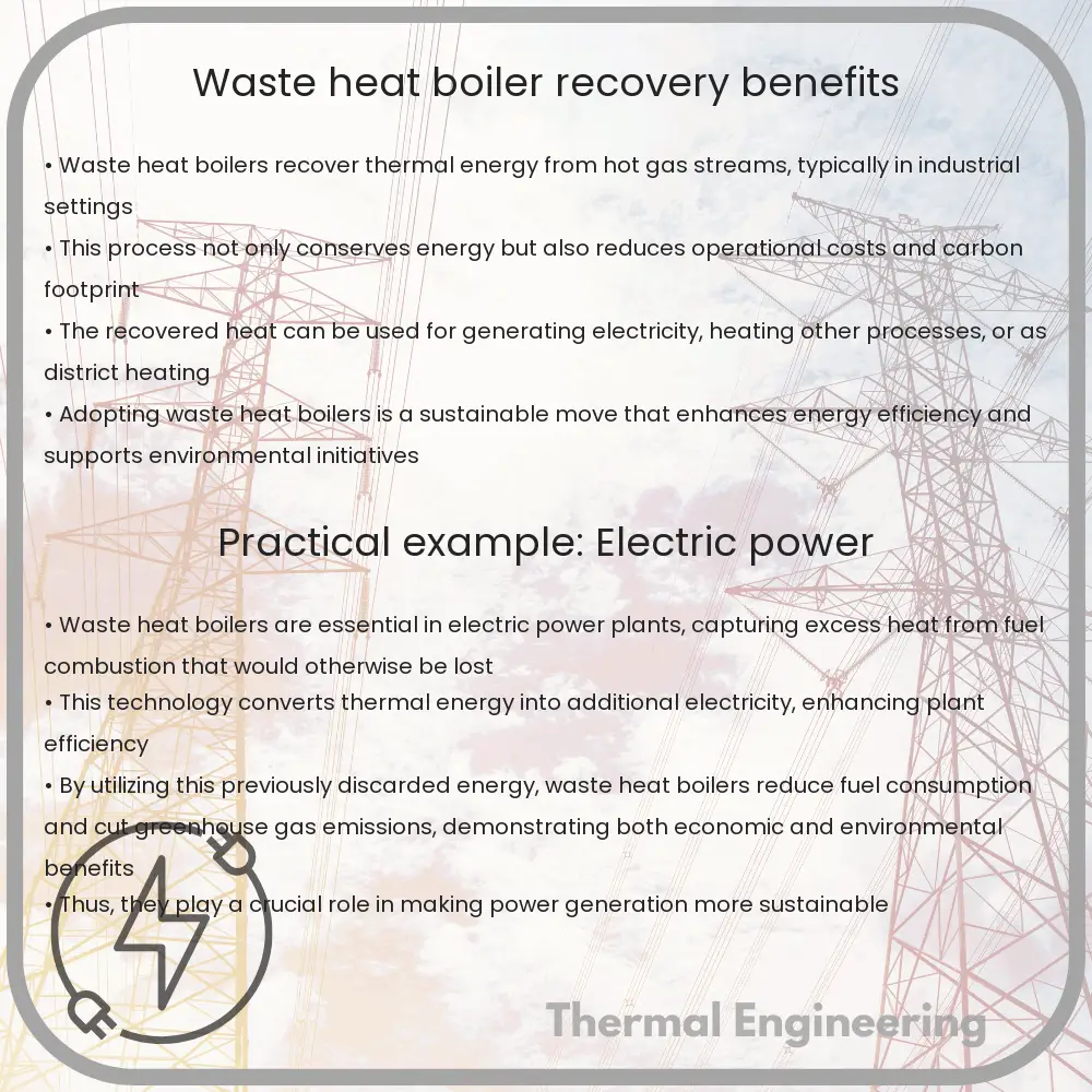
A waste heat boiler, commonly recognized within industries as a heat recovery steam generator (HRSG), is a vital component used to recover energy from the exhaust gases of various operations such as gas turbines, diesel engines, or processes that generate waste heat. This recovered energy is used to produce steam that can be utilized for various industrial applications, effectively enhancing the overall energy efficiency of a facility.

How Does a Waste Heat Boiler Work?

A waste heat boiler operates by capturing the high temperature exhaust gases from industrial operations and passing it over boiler tubes filled with water. These tubes are part of a closed loop, allowing the water to absorb heat and transform into high-pressure steam. The evolved steam can then be utilized for power generation, processing, or heating, depending on the requirements of the facility.

Key Components of a Waste Heat Boiler

  • Economizer: Preheats the feed water using residual heat, improving the efficiency of the system.
  • Evaporator: Turns the preheated water into steam by absorbing the main body of the heat from the exhaust gases.
  • Superheater: Increases the temperature of the steam above its saturation point, optimizing it for the power generating equipment.

Benefits of Using a Waste Heat Boiler

  • Enhanced Energy Efficiency: By recovering waste heat, facilities can substantially reduce fuel consumption, leading to reduced energy costs and dependency on external power sources.
  • Emission Reduction: Utilizing waste heat reduces the need to burn additional fossil fuels, leading to lower emissions of CO2, SOx, and NOx, which are significant contributors to air pollution and climate change.
  • Cost Savings: The reduction in energy consumption directly translates to significant cost savings in terms of reduced energy bills and operational costs.
  • Increased Process Efficiency: Heat recovery systems streamline various industrial processes by providing necessary heating or processing steam without extra energy input.

Applications of Waste Heat Boilers

Waste heat boilers find applications across a range of industries including:

  1. Power generation plants, where they utilize exhaust from gas turbines and diesel engines to generate additional power.
  2. Chemical plants, where they recover heat from chemical reactions to produce steam for heating or other process requirements.
  3. Steel mills, where they capture heat from the hot gases emitted from iron and steel production processes.
  4. Oil refineries, which employ waste heat boilers to recover energy from the refining processes.

Conclusion

Waste heat boilers play a pivotal role in enhancing energy efficiency, reducing operational costs, and contributing to environmental sustainability in industrial settings. By effectively harnessing the otherwise wasted energy, these systems provide a cost-effective solution for energy management in industries, making them an indispensable component in modern industrial operations.