Facebook Instagram Youtube Twitter

Steam Condenser | Design & Efficiency

Learn about steam condensers, their design, types, operational principles, and efficiency factors critical in power generation and industrial uses.
Steam Condenser | Design & Efficiency

Understanding Steam Condensers: Design & Efficiency

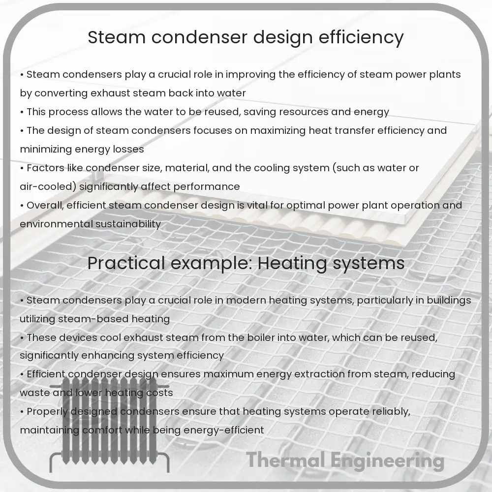
Steam condensers are critical components in both power generation and industrial processes, serving the primary function of condensing exhaust steam from a steam turbine into water. By converting steam to liquid form, condensers help maintain low turbine back pressure and facilitate the reuse of water, thereby enhancing the overall efficiency of the steam cycle. This article covers the basic design types of steam condensers, their operational principles, factors affecting their performance, and the methods to calculate their efficiency.

Types of Steam Condensers

  • Surface Condensers: In surface condensers, there is no direct contact between the cooling water and the exhaust steam. The exhaust steam is condensed on the outside of tubes through which the cooling water flows. It is the most commonly used type in power plants because it allows a high degree of water purity which is often needed for the boilers.
  • Jet Condensers (or Direct Contact Condensers): In jet condensers, the cooling water and the exhaust steam come into direct contact. This type is subdivided into parallel flow, counter flow, and mixed flow designs, depending on the direction of the steam and water flow. Jet condensers are typically more compact but do not offer the same level of water purity as surface condensers.
  • Air-cooled Condensers: These condense steam on finned tubes by air, which is either natural or forced by fans. This type is particularly used in situations where water usage needs to be minimized or where water disposal is challenging.

Design Considerations

When designing steam condensers, several factors need to be considered to ensure effectiveness and efficiency:

  • Materials: The choice of materials, particularly for the tubing, is critical as they need to resist corrosion, withstand high temperatures, and possess adequate thermal conductivity. Commonly used materials include titanium and stainless steel.
  • Cooling Water Quality: The quality of the cooling water can significantly impact the condenser’s performance. Impurities in the water can lead to scaling and fouling, which in turn affects the thermal conductivity.
  • Condenser Pressure: Lowering the condenser pressure can enhance the efficiency of the steam cycle but requires careful control to prevent negative effects like water ingress into the turbine.

Efficiency of Steam Condensers

Efficiency in steam condensers is primarily determined by their ability to maintain a low temperature of the condensed steam water mixture close to the saturation temperature. The efficiency (\(\eta\)) of a condenser can be expressed by the equation:

\[ \eta = \frac{T_{in} – T_{out}}{T_{in} – T_{sat}} \times 100\% \]

Where:

  • \(T_{in}\) is the temperature of the steam entering the condenser.
  • \(T_{out}\) is the temperature of the condensed liquid at the outlet of the condenser.
  • \(T_{sat}\) is the saturation temperature corresponding to the pressure inside the condenser.

This equation highlights the importance of maintaining a low outlet temperature and a minimal temperature difference between the outlet condensed water and the saturation temperature.

Conclusion

Steam condensers are crucial for the efficiency and effectiveness of steam power cycles, significantly influencing operational costs and environmental impact. With a comprehensive understanding of the different designs, material considerations, operational challenges, and calculation of efficiency, engineers can optimize condenser performance to meet energy production needs while adhering to environmental standards and economic constraints.
Energy-efficient thermal insulation techniques

Learn about the most effective thermal insulation techniques and materials to enhance building energy efficiency.

Energy-efficient thermal insulation techniques

Understanding Energy-Efficient Thermal Insulation Techniques

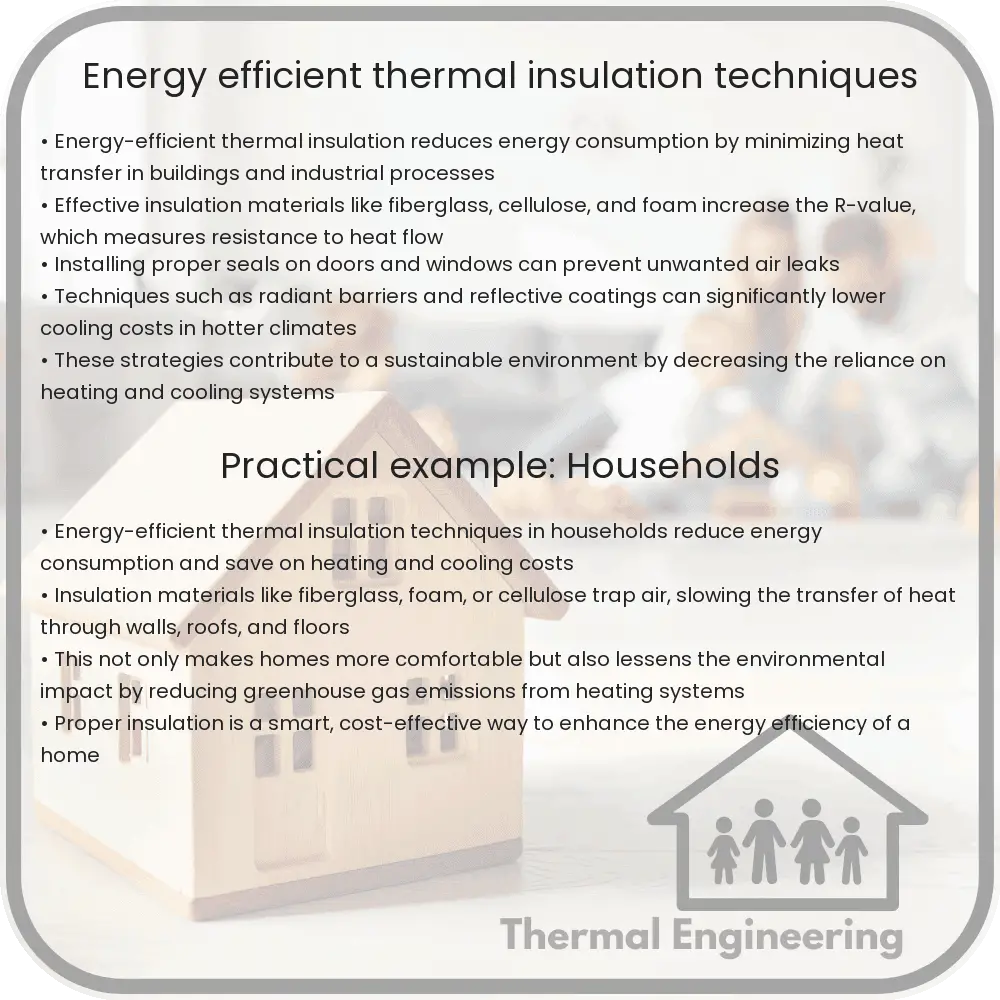
Thermal insulation plays a pivotal role in reducing energy consumption and improving the energy efficiency of buildings. It helps maintain indoor temperatures, thus lessening the load on heating and cooling systems. Effective insulation not only cuts down energy costs but also enhances comfort and reduces greenhouse gas emissions. Let’s explore some of the most efficient thermal insulation techniques and materials used in engineering today.

Types of Insulation Materials

Insulation materials are selected based on properties such as thermal conductivity, density, thickness, and environmental impact. Here are some common types of insulation materials:

  • Fiberglass: Composed of finely woven silicon, glass powder, and recycled glass, fiberglass is among the most prevalent insulation materials due to its low cost and effective thermal resistance.
  • Cellulose: Made from recycled paper products, primarily newsprint, cellulose is treated with chemicals to make it fire and insect resistant. It has a higher R-value per inch than fiberglass and is considered environmentally friendly.
  • Spray Foam: Available in open-cell or closed-cell forms, spray foam expands and hardens upon application, creating a tight thermal barrier. Closed-cell foam has a higher R-value and is more resistant to water vapor than open-cell foam.
  • Mineral Wool: Also known as rock wool or slag wool, mineral wool can be made from natural or synthetic materials. It offers superior fire resistance and acoustic properties.
  • Polystyrene: This includes both expanded polystyrene (EPS) and extruded polystyrene (XPS), which are rigid and provide good thermal resistance. XPS generally offers a greater insulation R-value.

Key Insulation Techniques

Choosing the right technique for applying insulation is crucial for maximizing its effectiveness. Some of the most commonly applied methods include:

  1. Batts and Rolls: These are flexible blankets of insulation that are easy to install between framing, such as in walls, floors, and ceilings. They’re best suited for standard spaces without many obstructions.
  2. Loose-fill and Blown-In: Ideal for irregularly shaped areas and for filling around obstructions. Cellulose or fiberglass are typically used, and the material is blown into place with special pneumatic equipment.
  3. Foam Board or Rigid Panels: These can be used to insulate almost any part of the home, from the roof down to the foundation. They are particularly effective for exterior wall sheathing and as a thermal barrier on roofs.
  4. Spray Foam: Applied using a spray container, this method is effective for adding insulation to existing finished areas, around obstructions, or in irregular spaces.
  5. Reflective or Radiant Barriers: While not traditional insulation, these barriers reflect thermal radiation rather than absorbing it, reducing cooling costs in warm climates.

Improving Energy Efficiency with Proper Installation

Even the best insulation materials can fail to perform optimally if not properly installed. Key points to ensure effective insulation include:

  • Air Sealing: Before adding new insulation, seal any air leaks. It’s essential for maximizing efficiency, as insulation is less effective when air is moving through it.
  • Correct R-Value: Insulation’s effectiveness is measured in R-values, which indicate an insulation material’s ability to resist heat flow. Higher R-values mean greater insulating power.
  • Comprehensive Coverage: Insulation must cover all areas without gaps, compression, or distortions, as these can significantly diminish insulation efficiency.

Energy-efficient thermal insulation is a key factor in building sustainability and reducing environmental impact while promoting significant economic benefits. By understanding and utilizing the right materials and techniques, engineers and builders can greatly enhance building performance and comfort.

Conclusion

Energy-efficient insulation is a crucial aspect of modern engineering, contributing significantly to the overall energy sustainability of buildings. By selecting appropriate materials and employing proper installation techniques, we can achieve optimal insulation performance, reduce energy consumption, and provide long-term environmental and financial benefits.

Cartridge Filter | Liquid Filtration & Purity

Learn about the design, function, and uses of cartridge filters in liquid filtration across various industries.

Cartridge Filter | Liquid Filtration & Purity

Understanding Cartridge Filters in Liquid Filtration

Liquid filtration is a crucial process in numerous industries, ranging from pharmaceuticals and food processing to water treatment and chemical manufacturing. One of the key components in many liquid filtration systems is the cartridge filter. This article explores the design, functioning, and applications of cartridge filters in maintaining liquid purity and quality.

What Is a Cartridge Filter?

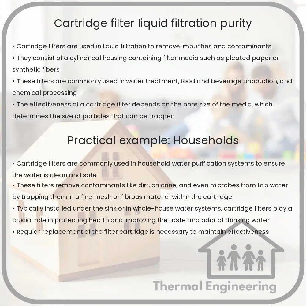
A cartridge filter is a disposable and replaceable element, typically housed within a filter housing, used to remove particles and contaminants from liquids. It consists of a central cylinder surrounded by filtering media which can be made from various materials depending on the specific application requirements. These filters are designed to offer high purity filtration and cover a broad range of micron ratings to target specific particle sizes.

Types of Cartridge Filters

  • Sediment Filters: Designed to remove solid particles like dirt, rust, and sand from liquids. They are commonly used in water treatment processes.
  • Carbon Filters: These filters use activated carbon and are effective in removing chlorine, odors, and taste from liquids. They are often used in food and beverage industries, as well as for potable water treatment.
  • Pleated Filters: Made from polyester or cellulose fibers, these filters have a high surface area, which allows for greater dirt holding capacity and longer service life.
  • Membrane Filters: These are used for fine filtration and bacteria removal. Commonly made from materials like polypropylene or ceramic, they are essential in pharmaceutical and biotechnological filtration applications.

How Cartridge Filters Work

The operational mechanism of a cartridge filter is based on physical barrier filtration. As the liquid passes through the filter media, particles larger than the pore size of the media are captured on the surface or within the depth of the media. The effectiveness of filtration depends on the micron rating of the filter, which indicates the size of particles it can effectively remove. For instance, a 5-micron filter will remove particles as small as 5 microns from the liquid.

Application and Maintenance

Cartridge filters are utilized in a wide array of settings, focusing on different aspects of liquid purification:

  1. Water Treatment: Removing particulates and chemical impurities to provide safe drinking water.
  2. Chemical Industry: Purification of chemicals and protection of processing equipment from particulate contaminants.
  3. Pharmaceuticals: Ensuring the sterility and cleanliness of products, especially in the production of injectables and solutions.
  4. Food and Beverage: Clarifying liquids and removing impurities to ensure quality and safety in consumables.

Maintenance of cartridge filters involves regular monitoring and replacement to prevent clogging and ensure optimal filtration performance. The frequency of replacement depends on the nature of the liquid being filtered, the volume processed, and the quality of the inlet fluid.

Key Considerations in Selecting a Cartridge Filter

Choosing the right cartridge filter involves considering several factors to match the filter characteristics with the specific filtration needs:

  • Particle Size: Selecting an appropriate micron rating based on the size of contaminants.
  • Chemical Compatibility: Ensuring the filter material is compatible with the liquid being filtered to avoid chemical degradation of the filter.
  • Flow Rate: Choosing a filter that can handle the desired flow rate without significant pressure drops.
  • Operational Conditions: Considering factors such as temperature and pressure of the filtration process.

In summary, cartridge filters play a vital role in numerous industries by effectively maintaining the purity and quality of liquids. Understanding the types, mechanisms, and proper maintenance of these filters can significantly enhance their efficiency and operational lifespan.

Water Hammer Arrestor | Shock Absorption & Noise Reduction

Learn about water hammer arrestors, devices that prevent plumbing damage by absorbing shocks caused by sudden water flow stoppage.

Water Hammer Arrestor | Shock Absorption & Noise Reduction

Understanding Water Hammer Arrestors

Imagine abruptly turning off a faucet and hearing a loud bang in the pipes. This noise, known as a water hammer, occurs when the flow of moving water is suddenly stopped by closing a valve, causing a pressure surge or wave to propagate back through the plumbing system. Water hammer can lead to noises, vibrations, and even damage to pipe systems. This is where water hammer arrestors come into play—they help mitigate these issues by absorbing the shock caused by the sudden stopping of water flow.

How Water Hammer Occurs

Water hammer typically happens because water is incompressible and possesses kinetic energy due to its motion. When a valve closes quickly, this kinetic energy must go somewhere. As a result, it creates a wave which moves back through the water in the pipes, causing increases in pressure and potential vibrations. The formula that describes the change in pressure, ΔP, due to a change in velocity, Δv, in a fluid with bulk modulus, B, and density, ρ, in a pipeline of diameter, D, and wave speed, a, is given by:

\[ \Delta P = \rho * a * \Delta v \]

Role of Water Hammer Arrestors

Water hammer arrestors are devices installed in plumbing systems to absorb the shock wave created by a water hammer. Typically, they consist of a chamber of air that is separated from the water line by a piston or diaphragm. The air inside the chamber acts as a cushion that absorbs the kinetic energy of the water wave, moderating the increase in pressure and reducing the resultant banging noise.

Types of Water Hammer Arrestors

  • Threaded Arrestors: These are screwed directly into appliance supply fittings, such as washing machines or dishwashers, and are suitable for residential applications.
  • Inline Arrestors: Installed in-line with the pipe system, these arrestors are used in both residential and commercial buildings.
  • Chamber Arrestors: These have larger air chambers. They are typically used in industrial applications where larger volumes of water and higher pressures are present.

Installation and Maintenance

Installing a water hammer arrestor requires selection of the appropriate size and type based on the specific characteristics of the plumbing system, such as pipe size, length, and the water pressure. Arrestors are usually installed near quick-closing valves, fixtures, and appliances that are likely to cause water hammer.

Regular maintenance of water hammer arrestors involves checking the integrity of the air cushion. Over time, the air can be absorbed into the water, diminishing the effectiveness of the arrestor. For some models, recharging the air chamber or replacing the arrestor may be necessary.

Benefits of Water Hammer Arrestors

Water hammer arrestors play a critical role in protecting plumbing systems from damage related to pressure surges. Their benefits include:

  • Protection of plumbing infrastructure: By mitigating the effects of pressure surges, arrestors prolong the lifespan of pipes and fittings.
  • Noise reduction: Arrestors help to eliminate the sounds associated with water hammer, leading to quieter plumbing systems.
  • Improved appliance lifespan: Appliances that are sensitive to high pressures benefit from the smoother flow of water that arrestors provide.

Understanding and employing water hammer arrestors help maintain the structural integrity and functionality of plumbing systems, thereby ensuring a quieter and more stable water delivery system in residential, commercial, and industrial settings.

Safety Valve | Safety & Overpressure Protection

Learn about safety valves, essential for overpressure protection in engineering systems, ensuring operational safety and equipment integrity.

Safety Valve | Safety & Overpressure Protection

Understanding Safety Valves: Key Components in Overpressure Protection

Safety valves are critical components in various engineering systems, where controlling pressure is essential to prevent potential hazards. These devices automatically release substances from a boiler, pressure vessel, or other systems when the pressure or temperature exceeds preset limits. By doing so, safety valves play a crucial role in ensuring operational safety and protecting equipment.

How Safety Valves Work

Safety valves function by releasing excess pressure from a system when it surpasses a designed threshold. They are typically spring-operated; the valve opens when the force of the steam or gas pressure against the valve overcomes the force of the spring. Once the pressure drops to a safe level, the spring forces the valve to close, thereby preventing the escape of the medium (e.g., steam, gas, or liquid).

Types of Safety Valves

  • Conventional Safety Valves: These valves have a spring loaded mechanism and are directly influenced by the back pressure (pressure in the discharge side).
  • Balanced Safety Valves: Designed to minimize the effect of back pressure on the valve’s performance, these valves employ bellows or a piston to balance the pressure.
  • Pilot-operated Safety Valves: Unlike spring-operated valves, these use system pressure to seal the valve through a pilot mechanism, which offers tighter control over the opening pressure.

Critical Parameters

Several key parameters must be considered when selecting and setting safety valves:

  1. Set Pressure: This is the pressure at which the safety valve is designed to open. It is typically set slightly above the system’s normal operating pressure to avoid frequent activation.
  2. Overpressure: Overpressure is the increase in pressure over the set point, usually expressed as a percentage. The maximum allowable overpressure is typically capped by codes and standards.
  3. Blowdown: Blowdown refers to the difference between the set pressure and the pressure at which the valve reseats (closes after being opened). It is also expressed as a percentage.

Applications of Safety Valves

Safety valves find applications across a wide range of industries:

  • Power Generation: In boilers and reactors, safety valves ensure that the pressure doesn’t build up to dangerous levels.
  • Oil and Gas: Used in pipelines and reactors to protect against overpressure due to heat or blockages.
  • Chemical Processing: To prevent pressure-related failures in chemical reactors and storage vessels.
  • Pharmaceuticals: Ensuring pressure stability in processes requiring high purity and control.

Standards and Regulations

Safety valves must adhere to international and local standards to guarantee reliability and safety. Common standards include the American Society of Mechanical Engineers (ASME) Code Section VIII for pressure vessels and the API 520 and 521 guidelines for sizing, selection, and installation of pressure-relieving devices.

Conclusion

Safety valves are indispensable in safeguarding industrial operations by managing overpressure and preventing equipment failure. In light of their critical role, selecting the right type of safety valve and maintaining it according to established codes and standards is paramount. Understanding how these devices operate and integrate within larger systems allows engineers and safety managers to ensure the stability, safety, and longevity of their operations.

Vacuum Pump | Types & Pressure Reduction

Learn about vacuum pumps, their types, and how they reduce pressure in various industrial applications.

Vacuum Pump | Types & Pressure Reduction

Understanding Vacuum Pumps: Types and Pressure Reduction

Vacuum pumps are essential devices in a variety of industries, from automotive to electronics manufacturing, where they are used to create a vacuum within a sealed environment. A vacuum is simply an area void of air or other gas, and vacuum pumps remove the air from an enclosed space to reduce the pressure. Reducing the pressure below atmospheric pressure creates a vacuum environment that can be utilized for various applications like packaging, scientific experimentation, and semiconductor processing.

Types of Vacuum Pumps

There are several types of vacuum pumps, each working on different principles and suitable for different levels of vacuum (low, medium, high) and applications. We’ll look into the three most common types: positive displacement, momentum transfer, and entrapment pumps.

  • Positive Displacement Vacuum Pumps: This type of pump repeatedly expands a cavity, allowing gases to flow in from the chamber, then seals the cavity and exhausts it to the atmosphere. The repeated action of expansion and sealing can achieve a lower pressure. Examples include rotary vane pumps and diaphragm pumps.
  • Momentum Transfer Vacuum Pumps: Also known as kinetic pumps, these work by accelerating the gas molecules from the vacuum side to the exhaust side, which is usually maintained at a reduced pressure by another vacuum pump. Common types include turbomolecular and diffusion pumps.
  • Entrapment Pumps: These pumps capture gases in a solid or adsorbed state and are used mainly for creating ultra-high vacuum. Common types include cryopumps, where gas is frozen, and getter pumps, where gas is bound chemically.

How Vacuum Pumps Reduce Pressure

The fundamental goal of a vacuum pump is to reduce the pressure within a vessel or system from atmospheric pressure (around 1013 mbar) to a lower pressure. The operating principle behind pressure reduction in vacuum pumps varies across different types, but generally follows these stages:

  • Exhaustion of Air: The pump removes air from the volume it is connected to. During this process, the pressure inside the volume decreases because there are fewer air molecules exerting force on the walls of the volume.
  • Maintenance of Low Pressure: Once the desired vacuum level is reached, the pump needs to work continuously to remove new air molecules entering the system from leaks or outgassing materials within the chamber.

The degree to which a vacuum pump can reduce the pressure is described by its ultimate pressure rating, typically in units of mbar, Pa, or torr.

Applications of Vacuum Pumps

Vacuum pumps are critical in many applications that require the maintenance of a low-pressure environment:

  • Electronics Manufacturing: Used in lithography and etching processes for creating microelectronics and semiconductors.
  • Pharmaceuticals: Employed in freeze-drying processes which remove water from perishable medications to increase their shelf life.
  • Automotive: Utilized in the manufacture of lamps and other sealed components, as well as in vacuum forming processes for plastic components.
  • Scientific Research: Essential in experiments that study physical phenomena under vacuum conditions or that require controlled atmospheric conditions.

The choice of vacuum pump and its correct application is crucial for the success of these tasks, influencing efficiency, productivity, and product quality.

In conclusion, understanding different types of vacuum pumps and how they work helps in selecting the right pump for the right application. This ensures operational efficacy and can lead to significant gains in both experimental research and industrial production, making vacuum technology an indispensable part of modern engineering and manufacturing processes.

Desuperheater | Efficiency in Steam Temperature

Learn about desuperheaters: devices key to controlling and enhancing the efficiency of steam temperatures in industrial applications.

Desuperheater | Efficiency in Steam Temperature

Understanding Desuperheaters: Enhancing Efficiency in Steam Temperature Control

In the realm of steam systems used in industrial applications and power generation, the management of steam temperature is crucial for efficiency and safety. A commonly used device to regulate steam temperature is the desuperheater. This article explores what desuperheaters are, their importance, and how they operate to achieve temperature efficiency in steam processes.

What is a Desuperheater?

A desuperheater is a device that lowers the temperature of superheated steam in a power generation cycle, making the heat transfer process more efficient and enhancing the overall system’s thermal efficiency. It typically works by injecting a controlled amount of water directly into the steam flow, which rapidly cools the steam to a desired temperature closer to its saturation point.

Key Components and Working Principle

The main components of a desuperheater include a water injection nozzle, temperature sensors, and control valves. The operation of a desuperheater is primarily based on the principle of heat exchange where water, injected through the nozzle, evaporates into the steam, consequently reducing its temperature.

  • Water Injection Nozzle: Delivers a finely atomized spray of water into the steam pipe.
  • Temperature Sensors: Monitor the temperature of the steam both before and after the desuperheating process.
  • Control Valves: Regulate the amount of water injected based on feedback from the temperature sensors to achieve the desired steam temperature.

Importance of Steam Temperature Control

Controlling the temperature of steam is vital for several reasons:

  1. Safety: High temperatures can lead to pipe and equipment damage due to thermal stress.
  2. Efficiency: Proper temperature control ensures that steam carries the optimum amount of energy for processes downstream.
  3. Process Necessity: Many industrial processes require steam at specific temperatures for effective operation.

Efficiency Considerations

Desuperheaters play a significant role in improving the efficiency of steam systems by reducing energy loss. Cooler, near-saturated steam has a lower volume, requiring less energy for transport and reducing wear and tear on pipelines and equipment.

Types of Desuperheaters

There are various types of desuperheaters available, each suited for different operating conditions:

  • Venturi Type Desuperheater: Utilizes a venturi tube to create a pressure drop that aids in water atomization.
  • Attemperator: Often used in boilers and large steam systems to provide fine control over steam temperature.
  • Annular Type Desuperheater: Features a ring-shaped nozzle that delivers water around the circumference of the steam pipe, promoting rapid mixing and heat exchange.

Conclusion

Efficient management of steam temperature using desuperheaters is crucial for maximizing the performance and longevity of steam-based systems in various industrial settings. By understanding different types of desuperheaters and their specific uses, engineers can design more effective and safer steam distribution networks. Importantly, by optimizing desuperheater operations, industries can achieve significant energy savings, contributing to more sustainable manufacturing practices.

The application of desuperheaters, therefore, not only supports industrial efficiency but also plays a vital role in enhancing process quality and energy management in high-demand steam applications.

Plate & Frame Filter Press | Wastewater & Sludge Dewatering

Learn how the Plate & Frame Filter Press operates in wastewater and sludge dewatering, its applications, and its benefits for water treatment processes.

Plate & Frame Filter Press | Wastewater & Sludge Dewatering

Understanding the Plate & Frame Filter Press in Wastewater & Sludge Dewatering

The Plate & Frame Filter Press is a significant piece of equipment used in the process of dewatering in wastewater treatment. As industries and municipalities face increasing challenges related to water conservation and waste reduction, understanding the functionality and efficiency of this system is crucial. This article aims to demystify the mechanics and application of the plate and frame filter press in wastewater and sludge dewatering processes.

What is a Plate & Frame Filter Press?

A plate and frame filter press is an industrial machine used to separate solids and liquids in filter media. It operates on a simple mechanism involving pressure and filtration. The basic components include a series of plates and frames assembled alternately in a form that creates a series of chambers for sludge dewatering.

How Does It Work?

The working process of a plate and frame filter press involves several key steps:

  1. Sludge Feeding: Sludge is pumped into the press at high pressure, typically between 3 to 15 bars, filling up the chambers formed by the plates and frames.
  2. Filtration: The sludge pressure forces water to pass through the filter cloths that cover each plate while solids are retained, forming a ‘cake’.
  3. Cake Discharge: After the sludge feeding is stopped, the separated solid cakes are discharged from the filter press.

The efficiency of filtration often depends on the nature of the sludge, the type of filter cloth, the size of the plates, the pressure applied, and the total time allowed for the filtration process.

Applications in Wastewater Treatment

In wastewater treatment, the plate and frame filter press is used for the dewatering of biological or chemical sludges from municipal or industrial wastewater treatment plants. This process helps in reducing the moisture content of sludge, thus minimizing its weight and volume. It is an essential step before sludge can be disposed safely, or used as fertilizer, incinerated, or landfilled.

Advantages of Using Plate & Frame Filter Press

  • High Efficiency: Capable of producing filter cakes of up to 50% total solids by weight.
  • Cost-Effective: Helps in reducing the cost associated with sludge disposal due to decreased volume and weight.
  • Customizable: Available in varying sizes and configurations to meet specific requirements of different treatment plants.
  • Eco-Friendly: Assists in the reduction of environmental impact as it facilitates the reuse and recycling of wastewater.

Limitations and Considerations

While the plate & frame filter press offers numerous benefits, there are limitations and operational considerations to account for:

  • Initial Investment: The cost of installation and setup can be considerable.
  • Maintenance: Regular maintenance is required to ensure operational efficiency and longevity of the equipment.
  • Handling of Chemicals: Handling and disposal of the chemicals used in the process need to be managed safely and responsibly.

Conclusion

The plate & frame filter press remains a pivotal element in the arsenal for managing wastewater and sludge dewatering. By understanding its operating mechanism, scope of application, advantages, and limitations, industries can make informed decisions about integrating this system into their operations. As such, it not only addresses environmental concerns but also enhances operational efficiencies and sustainability in wastewater management.

Blower | Air Movement & Industrial Ventilation

Learn about the essential roles of blowers in air movement and industrial ventilation, their types, components, and principles of operation.

Blower | Air Movement & Industrial Ventilation

Understanding Blowers: Essential Tools for Air Movement and Industrial Ventilation

Blowers are a crucial component in many industrial and commercial settings, playing a vital role in air movement and ventilation systems. These devices are designed to move air at high volumes and are widely used in various applications ranging from household heating, ventilation, and air conditioning (HVAC) systems to heavy-duty industrial processes.

Types of Blowers

There are several types of blowers, each suited to specific applications based on their operational mechanics and efficiency. The most commonly used types include:

  • Centrifugal Blowers: Often referred to as radial fans, centrifugal blowers have a wheel with blades mounted perpendicularly to the axis, effectively directing air outwards in a direction at right angles to the intake direction. They are particularly efficient for high-pressure applications.
  • Axial Blowers: In axial blowers, the air flows parallel to the axle or shaft. These are typically used where a large volume of air needs to be moved across relatively low pressure.
  • Positive Displacement Blowers: These blowers trap air and then push (displace) that volume into the discharge pipe, which is ideal for high-pressure applications at relatively low volumes.

Key Components and Design

The design of a blower system is critical to its efficiency and effectiveness. The key components include:

  • Motor: Supplies power to the blower for operation.
  • Impeller/Blades: Responsible for moving air. The design and number of blades affect performance.
  • Housing: Contains the components and directs the airflow.

Blower efficiency depends heavily on its design. The design considerations include the diameter of the impeller, rotational speed, and the number of blades, all of which directly impact the airflow rate and pressure generated by the blower.

Principles of Operation

Blowers increase air velocity using one of the following principles:

  1. Momentum Addition: By increasing the kinetic energy of the air, leading to an increase in air velocity.
  2. Pressure Increase: Creating a pressure difference which naturally causes air to move from a region of high pressure to low pressure.

These principles are applied based on the specific type of blower. For instance, centrifugal blowers often use dynamic pressure to move air, whereas positive displacement blowers push air through mechanical means.

Applications of Blowers

Blowers are used in a wide range of industries for various applications, including:

  • Industrial ventilation and air pollution control systems.
  • Pneumatic conveying in material handling systems.
  • Combustion air supplies for furnaces and boilers.
  • Cooling and drying systems.
  • Vacuum applications in printing and paper processing.

Conclusion

Blowers are invaluable in providing controlled air movement necessary for industrial, commercial, and domestic environments. Understanding the different types of blowers, designs, and operational principles helps in selecting the right blower for specific applications, ensuring efficiency and effectiveness. As technology advances, innovations in blower design continue to enhance their capability, making them more adaptable and energy-efficient.

Understanding the basic function and applications of blowers provides a foundational knowledge that is crucial for anyone involved in the engineering, operation, or maintenance of HVAC and industrial ventilation systems.

Manifold | Fluid Distribution & Hydraulic Systems

Learn about manifolds in fluid distribution, their functionality, types, design considerations, and applications in hydraulic systems.

Manifold | Fluid Distribution & Hydraulic Systems

Understanding Manifolds in Fluid Distribution and Hydraulic Systems

In the world of engineering, a manifold refers to a component that connects multiple inputs or outputs in hydraulic and pneumatic systems, facilitating the distribution and management of fluids or gases. The manifold serves the crucial function of ensuring that fluids are directed appropriately within the system, which enhances efficiency and performance in various applications such as automotive engines, aerospace, and industrial machinery.

Functionality of Manifolds

A manifold typically consists of a series of channels that can merge or split the flow of fluids. This allows it to effectively manage the distribution of fluids from one point to multiple endpoints or vice versa. The core functionalities of a manifold include:

  • Distribution: Dividing a single flow into multiple outputs, making it essential for systems requiring uniform fluid distribution to various components.
  • Collection: Combining different fluid streams into a single channel. This is commonly used in systems where fluids from several sources need to be processed or disposed of simultaneously.

Types of Manifolds

There are mainly two types of manifolds used in fluid dynamics and hydraulics:

  1. Hydraulic Manifolds: Used in hydraulic systems to regulate fluid flow between pumps, actuators, and other components through solenoid valves and channels. The design often involves a block of metal (such as steel or aluminum) with various ports and pathways machined into it.
  2. Pneumatic Manifolds: Applied in pneumatic systems to direct air flow. These manifolds tend to be lighter and are used for controlling the distribution of pressurized air in various industrial applications.

Design and Material Considerations

When designing a manifold, engineers must consider several factors to ensure efficiency and safety:

  • Material: The choice of material must withstand the specific type and temperature of fluid, as well as the operational pressure of the system. Common materials include aluminum, stainless steel, and brass.
  • Configuration: The design and configuration of the ports and passageways in a manifold must minimize pressure drop and avoid areas where fluid might stagnate, which can lead to inefficiencies or damage.
  • Size: The size of the manifold should align with the system’s volume and flow rate requirements, ensuring that it can manage fluid distribution effectively without being overly large or cumbersome.

Applications of Manifolds in Engineering

Manifolds are essential in a range of engineering applications:

  • In automotive engineering, manifolds distribute coolant to the engine block and manage exhaust gases.
  • In aerospace, hydraulic manifolds operate flight control systems by distributing hydraulic fluid under high pressure.
  • In manufacturing, pneumatic manifolds are used to power automated assembly lines using controlled bursts of air.

Understanding how manifolds operate and their applications in fluid and hydrodynamic systems is crucial for anyone involved in engineering design, maintenance, or troubleshooting of these systems. Whether in a high-tech aerospace setting or a simple manufacturing line, manifolds play a key role in enhancing the performance and reliability of fluid distribution systems.