Facebook Instagram Youtube Twitter

Pressure Vessel | High Pressure Storage & Safety

Learn about pressure vessels, their design, materials, safety features, and regulatory standards for optimal industrial use.
Pressure Vessel | High Pressure Storage & Safety

Understanding Pressure Vessels: High Pressure Storage & Safety

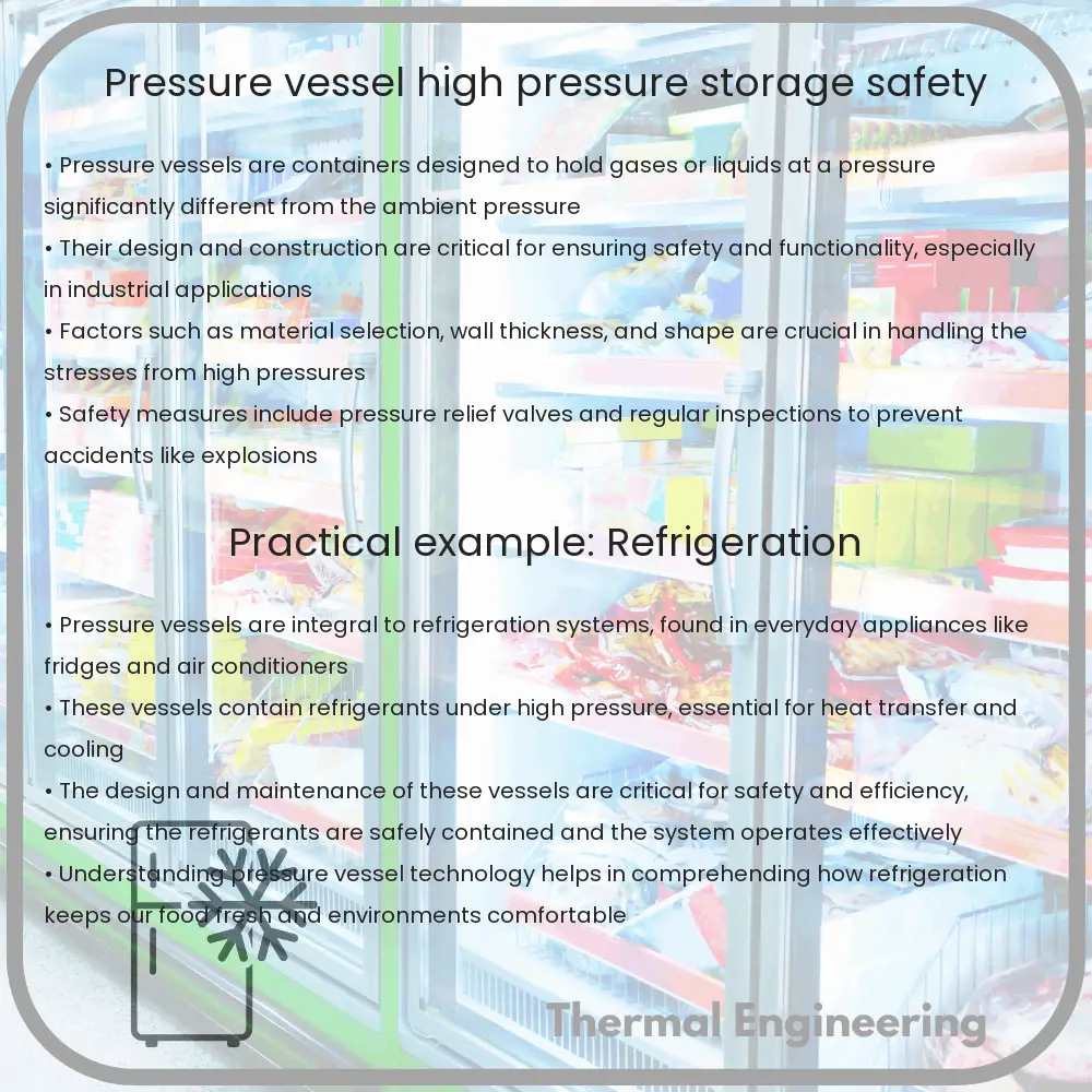
Pressure vessels are containers designed to hold gases or liquids at a pressure substantially different from the ambient pressure. They are a fundamental part of industries ranging from petrochemical to the food and beverage sector. Understanding their design, operation, and safety is crucial for maintaining industrial safety and efficiency.

Basic Design of Pressure Vessels

The design of a pressure vessel takes into account the pressure (both internal and external), temperature, and the properties of the material contained and of the vessel material. Common shapes include spheres, cylinders, and cones. The choice of shape largely depends on the balance of stress, cost, and space considerations.

  • Cylindrical vessels: With a circular cross-section, they are selected for their ability to evenly distribute stress throughout the structure.
  • Spherical vessels: Spheres are preferred when high pressure is involved as they handle stress more uniformly than any other shape.
  • Conical ends or heads: Used in conjunction to cylindrical shapes for better pressure distribution.

Material Considerations in Pressure Vessel Design

The material used to build a pressure vessel can seriously impact its performance and safety. Steel, particularly stainless steel, is a common choice due to its strength and resistance to corrosion. Composite materials, like carbon fiber, are also used where lighter weight or higher strength are required.

Manufacturers frequently conduct tests, including hydrostatic testing and ultrasonic testing, to ensure the integrity of the material and the construction of the vessel.

Common Equations in Pressure Vessel Design

One of the fundamental calculations in the design of pressure vessels is determining the wall thickness required to withstand a specified internal pressure without failing. The formula used is derived from the hoop stress equation:

Thickness (t) = (P * r) / (S * E – P)

  • P = internal pressure
  • r = inner radius of the cylinder
  • S = allowable stress for the material at operating temperature
  • E = efficiency of welded joints (typically 1 for seamless construction)

This equation is crucial for engineers to design a vessel that can safely handle the specific pressures to which it will be subjected in operation.

Pressure Vessel Safety Features

The operation of pressure vessels is regulated through engineering standards and codes to enhance their safety and reliability. Key safety components include:

  • Pressure relief valves: These automatically release pressure when it exceeds a certain limit, preventing potential explosions.
  • Safety shutoffs: They detect unsafe operating conditions and shut down the process to prevent accidents.
  • Burst disks: These are designed to rupture and release pressure as a last line of defense if primary safety systems fail.

Regulations and Codes

In the United States, the design, construction, and operation of pressure vessels are governed by codes such as the ASME Boiler and Pressure Vessel Code. Internationally, standards such as the ISO 9001 for quality management ensure that pressure vessels are designed and manufactured to meet safety requirements.

It is crucial for organizations to comply with these regulations not only to enhance safety but also to minimize legal and financial liabilities.

Conclusion

Pressure vessels are integral components across various industries, tasked with safely containing gases and liquids at high pressures. Understanding the engineering behind their design, material choice, and the associated safety protocols is essential for managing industrial risks and enhancing operational efficiency. By rigorously adhering to safety standards and regular maintenance schedules, pressure vessels can be operated safely and reliably, supporting the demands of modern industrial processes.

Centrifugal Separator | Fluid Separation & Force

Learn how centrifugal separators use centrifugal force to separate fluid components in various industries, enhancing efficiency and purity.

Centrifugal Separator | Fluid Separation & Force

Understanding Centrifugal Separators

Centrifugal separators are vital devices used in various industries to separate different components of fluids using centrifugal force. They operate on the principle of sedimentation, where centripetal acceleration is used to separate substances with different densities.

How They Work

Centrifugal separators rotate a mixture in a vessel at high speed, creating a force that pulls heavier particles outward, towards the edge of the vessel. By contrast, lighter components are pushed towards the center. The process rides on the fundamental physics of motion and the influence of centrifugal force, summed up by the formula:

Fc = m * ω2 * r

  • Fc – Centrifugal force
  • m – Mass of the particle
  • ω – Angular velocity (in radians per second)
  • r – Radius from the center to the particle

Applications of Centrifugal Separators

Centrifugal separators are used across many fields such as:

  • Dairy Industry: To separate cream from milk.
  • Oil Industry: To separate particles and sediment from crude oil.
  • Waste Management: To separate solids from wastewater.

Advantages of Centrifugal Separators

The primary advantages of centrifugal separators include their efficiency and versatility. They can rapidly process large volumes of fluids with minimal maintenance. Moreover, they offer an effective method for clarifying liquids and can even work under extreme temperatures and pressures.

Limitations and Challenges

While effective, centrifugal separators also come with challenges:

  • Power Consumption: They require significant amounts of energy to generate the required centrifugal force.
  • Operational Skills: Proper operation demands precise control and understanding of the rotational mechanics.

Conclusion

Centrifugal separators play a crucial role in processing and refining fluids in numerous industries by harnessing fundamental principles of physics. Depending on their design, these devices are capable of achieving high levels of purity in separation tasks, making them invaluable in industrial applications.

Hydraulic Cylinder | Mechanical Force & Construction

Learn about hydraulic cylinders, their mechanism, components, and applications in various industries to understand their critical role in mechanical engineering.

Hydraulic Cylinder | Mechanical Force & Construction

Understanding Hydraulic Cylinders: Mechanical Force and Construction

Hydraulic cylinders are fundamental components widely used in engineering to convert the stored energy of hydraulic fluid into a force used to perform work. This article explores the basic principles behind hydraulic cylinders, how they generate force, and their construction.

What is a Hydraulic Cylinder?

A hydraulic cylinder is a mechanical actuator that provides unidirectional force through unidirectional stroke. It is commonly used in a variety of machinery, including construction equipment, manufacturing machinery, and civil engineering devices.

Components of a Hydraulic Cylinder

  • Cylinder Barrel: The main body of the cylinder in which the piston moves back and forth.
  • Piston: A disc or short cylinder fitting closely within the barrel that divides the cylinder into two chambers.
  • Piston Rod: Connects the piston to the machine component doing the work.
  • Cylinder Base and Head: The ends of the cylinder that enclose the piston inside the cylinder barrel.
  • Seals: Prevent fluid from leaking from the cylinder.

How Hydraulic Cylinders Work

Hydraulic cylinders operate under the principle of Pascal’s Law, which states that when there is an increase in pressure at any point in a confined fluid, there is an equal increase in pressure at every other point in the container. In simple terms, force applied at one end of the fluid is transmitted to another end using an incompressible fluid, typically oil.

The basic operation involves two ports connected to the cylinder: one for the inflow and one for the outflow of the hydraulic fluid. When the fluid enters through the inflow port, it pushes against the piston, causing it to move, thereby extending the piston rod. The movement of the piston rod generates mechanical force that can be used to perform various tasks, like lifting heavy loads or crushing materials.

Hydraulic Cylinder Force Calculation

The force generated by a hydraulic cylinder can be calculated using the formula:

F = P * A

Where:

  • F is the force in Newtons,
  • P is the pressure in the cylinder in Pascals, and
  • A is the cross-sectional area of the piston in square meters.

For example, if a hydraulic cylinder has a piston with a diameter of 0.1 meters and the system pressure is 2,000,000 Pascals, then the cross-sectional area (A) = π * (0.1/2)2 ≈ 0.0079 m2. Substituting the values in the equation:

F = 2,000,000 * 0.0079 = 15,800 Newtons.

Construction and Materials

Hydraulic cylinders are built to endure high pressures and harsh working environments. They are typically made from high-strength steel and iron components. The surface of the piston rod is often hardened or coated to resist wear and corrosion. Seals made from rubber or polyurethane are used to keep the hydraulic fluid inside the cylinder and prevent contaminants from entering the system.

The choice of material and the construction design depend on the specific requirements of the application, including load, speed, working environment, and expected lifespan of the cylinder.

Applications of Hydraulic Cylinders

Hydraulic cylinders find applications across a broad spectrum of industries. They are essential in:

  • Automotive industry for lifting during repairs,
  • Construction for machinery such as excavators and bulldozers,
  • Manufacturing for pressing operations or handling heavy loads,
  • Aerospace for controlling wing movements and landing gears.

In conclusion, hydraulic cylinders are powerful examples of how fundamental physics principles can be harnessed to create tremendously useful systems, powering everything from small machines to large industrial equipment. Their robust construction and dependable operation make them indispensable in many aspects of modern engineering.

Duct Heater | HVAC Efficiency & Electric Operation

Learn about duct heaters, essential for adding supplemental heat in HVAC systems, improving comfort and energy efficiency.

Duct Heater | HVAC Efficiency & Electric Operation

Understanding Duct Heaters in HVAC Systems

Duct heaters are a vital component in many Heating, Ventilation, and Air Conditioning (HVAC) systems, particularly useful in generating additional heat when required. Their design and operation directly affect the efficiency and functionality of HVAC systems, especially in residential, commercial, and industrial settings.

What are Duct Heaters?

A duct heater is an electric heating unit installed within the ductwork of an HVAC system. Its primary function is to add supplemental heat to the air passing through the ducts, ensuring that the temperature is adequately maintained throughout the entire space of a building or facility.

Types of Duct Heaters

There are several types of duct heaters, each designed to suit particular applications and efficiency needs:

  • Electric resistance heaters: These are the most common type, using electric resistance elements to generate heat when electric current passes through them.
  • Steam or hot water heaters: Utilize steam or hot water generated by a boiler to heat the air, suitable for systems where a boiler is already in place.

Components of Duct Heaters

Key components of duct heaters include:

  • Heating elements: Typically made of nickel chromium (NiCr) wire, these are the core components that heat up as electric current flows through them.
  • Thermostats: Regulate the temperature by switching the heating elements on and off based on the temperature setpoint.
  • Controls and safety devices: Such as contactors, fuses, and overload relays that ensure the heater operates safely and efficiently.

How Do Duct Heaters Enhance HVAC Efficiency?

Duct heaters play a crucial role in enhancing HVAC efficiency in several ways:

  • Zone control: They allow for the heating of specific zones within a building, which can lead to significant energy savings by heating only the areas that require warmth.
  • Quick response: Electric duct heaters provide immediate heat, which can be beneficial in rapidly changing weather conditions or in buildings with varying occupancy levels.
  • Supplemental heating: They help maintain desired temperatures without overburdening the primary HVAC system, especially during extremely cold weather.

Electric Operation and Safety

The operation of electric duct heaters is straightforward but must be handled with care to avoid safety hazards such as overheating or electrical fires. Key operational practices include:

  • Maintaining proper airflow: Adequate airflow across the heating elements is crucial to prevent overheating and extend the lifespan of the heater.
  • Regular maintenance: Periodic checks and maintenance of the heater’s components are necessary to ensure efficient operation and safety.

Installation and Considerations

Proper installation of duct heaters is critical to their performance and safety. Installation considerations include:

  • Ensuring compatibility with existing ductwork and HVAC systems.
  • Correct sizing of the heaters to meet the specific heating loads without excessive energy consumption.
  • Compliance with local codes and standards regarding electrical systems and heating devices.

Conclusion

Duct heaters are an efficient solution for enhancing the performance and comfort of HVAC systems. By understanding the different types of duct heaters, their components, and operational dynamics, building managers can optimize their heating needs while ensuring safety and energy efficiency.

Heat transfer in multiphase flows

Learn about heat transfer in multiphase flows, a complex engineering phenomenon critical for various industrial processes.

Heat transfer in multiphase flows

Understanding Heat Transfer in Multiphase Flows

Heat transfer in multiphase flows is a critical area of research and application within the field of engineering. This complex phenomenon is encountered in various industrial processes, including power generation, chemical processing, and environmental control systems. To fully grasp the essentials of this topic, it’s important to understand what multiphase flows are and how heat transfer occurs within them.

What are Multiphase Flows?

Multiphase flows involve the simultaneous flow of materials in different phases — solid, liquid, or gas. For instance, in boiling water, the water represents the liquid phase and the steam represents the gas phase. Such flows can be highly complex due to the interactions between different phases which significantly affect the flow behavior and heat transfer characteristics.

Types of Multiphase Heat Transfer

The three primary mechanisms of heat transfer — conduction, convection, and radiation — can occur in multiphase flows. In these flows, the complexity increases as the different phases generally have distinct thermal properties and dynamic behaviors. Below we explore how each mechanism plays a role:

  • Conduction: Heat transfer by conduction occurs due to the temperature gradient within a phase or between different phases in direct contact. The thermal conductivity of each phase plays a crucial role in determining the rate of heat transfer.
  • Convection: This mechanism involves the movement of heat due to the fluid motion of one or more phases. In multiphase flows, convection can be influenced by factors such as phase changes, flow turbulence, and relative velocities between phases.
  • Radiation: Although less common in comparison to conduction and convection, radiation can occur particularly in high-temperature environments. It involves the transfer of heat through electromagnetic waves without any physical contact between the phases.

Challenges in Multiphase Flow Heat Transfer

Analyzing heat transfer in multiphase flows poses several challenges:

  1. Interfacial dynamics: The interfaces between different phases can dramatically affect heat transfer rates. The stability, shape, and movement of these interfaces are critical factors.
  2. Phase change: Events like boiling or condensation add complexity due to the latent heat involved. Accurately modeling these phase changes is crucial for predicting heat transfer.
  3. Non-uniform properties: Variable properties like density, specific heat, and thermal conductivity can change with temperature, pressure, and phase composition.

Practical Applications

Multiphase flows and their associated heat transfer characteristics are relevant in many engineering fields:

  • Energy systems: In power plants, multiphase flows are key in processes such as steam generation and condensation in heat exchangers.
  • Chemical engineering: In reactors and separators, understanding multiphase flows helps in optimizing the heat transfer for improved reaction rates and system safety.
  • Cooling technologies: Effective multiphase flow management enhances the performance of cooling systems, crucial in electronics and automotive industries.

Heat transfer in multiphase flows is a dynamic and essential area of study in the field of engineering. By developing a better understanding of this phenomenon, engineers can design more efficient and effective systems in a wide range of industrial applications.

Cooling Tower Fill | Heat Transfer & Evaporative Cooling

Learn about cooling tower fill, its role in heat transfer and evaporative cooling, and the types of fills for efficient cooling tower operation.

Cooling Tower Fill | Heat Transfer & Evaporative Cooling

Cooling Tower Fill: Understanding Heat Transfer & Evaporative Cooling

In the world of industrial engineering, cooling towers play a crucial role in maintaining optimal temperatures in various processes. The cooling tower fill is an essential component of cooling towers as it enhances the heat exchange process. This article will explore what cooling tower fill is, its function in heat transfer and evaporative cooling, and the types of fills used in cooling towers.

What is Cooling Tower Fill?

Cooling tower fill refers to the material placed within the cooling towers to increase the surface area available for the heat exchange between air and water. The main purpose of the fill is to facilitate the spread of water into a thin film, increasing water-air contact time, and thereby maximizing heat rejection. This function is vital for the efficient operation of a cooling tower.

How Does It Work?

When hot water enters the cooling tower, it is distributed uniformly across the fill material. As the water trickles down the fill’s layers, it forms a thin film over the surfaces. During this process, the heat from the water is transferred to the air. This transfer happens mainly by evaporation and convection. A cooling tower’s effectiveness largely depends on the amount of surface area the fill provides and how it facilitates the distribution and evaporation of water.

Types of Cooling Tower Fills

  • Splash Fill: This type of fill breaks the falling water into small droplets, increasing the water-air interface and enhancing heat transfer. Splash fills are usually used in industrial cooling towers where the water contains more impurities.
  • Film Fill: Consists of thin, closely packed sheets of material that form a labyrinth of vertical flutes, which the water streams down. Film fill promotes the spread of water into a thin film, which is optimal for heat transfer via evaporation. It is typically used in cleaner water environments as it can be blocked by debris more easily than splash fill.

Material Choices for Fills

The materials used for cooling tower fills must be durable and resistant to the harsh conditions inside the tower, like high temperatures and exposure to chemicals. Here are common materials:

  • Polyvinyl Chloride (PVC): Widely used due to its resistance to heat and chemicals. It is effective up to temperatures around 55°C.
  • Polypropylene (PP): Withstands higher temperatures than PVC and is also chemical resistant, making it suitable for hotter applications.

Importance of Proper Fill Selection

Choosing the right type of fill and material is crucial for operational efficiency. Wrong selection can lead to fill fouling, where the fill gets clogged with mineral deposits and impurities, reducing the cooling tower’s efficiency. It can also lead to higher energy consumption and operational costs. Therefore, understanding the specific needs and conditions of your cooling process is essential for selecting the appropriate fill.

Conclusion

Cooling tower fill is a pivotal component in the heat transfer process of cooling towers through evaporative cooling. By enhancing water-air contact, fills significantly impact a cooling tower’s performance. Whether it’s splash or film type, the effectiveness of the fill depends on its ability to distribute water evenly and maximize surface area for heat exchange. With the correct fill, cooling towers can operate optimally, providing substantial energy savings and efficacy in industrial and HVAC applications.

Ultrasonic Flow Meter | Accuracy in Liquid/Gas

Learn about the mechanisms, types, and factors affecting the accuracy of ultrasonic flow meters used in measuring liquid and gas flow.

Ultrasonic Flow Meter | Accuracy in Liquid/Gas

Understanding Ultrasonic Flow Meters: Principles and Accuracy in Measuring Liquid and Gas Flow

Ultrasonic flow meters are sophisticated devices used to measure the velocity of a fluid with ultrasound to calculate volume flow. Utilizing the properties of ultrasonic waves, these meters are applicable across various industries, including water management, oil and gas, and chemical processing. Crucially, their capability to measure the flow of both liquids and gases accurately makes them indispensable tools in fluid dynamics.

How Ultrasonic Flow Meters Work

Ultrasonic flow meters operate by transmitting ultrasonic sound waves through the medium being measured. There are two primary types of ultrasonic flow meters: transit-time and Doppler flow meters. Each type leverages the behavior of ultrasonic waves differently when interacting with flowing media.

  • Transit-Time Ultrasonic Flow Meters: These meters use two transducers, which function alternately as emitter and receiver. The flow meter measures the time it takes for an ultrasonic signal to travel downstream and upstream between these transducers. The difference in transit times, downstream versus upstream, is used to calculate the flow velocity based on the formula:

    V = (d * (tup – tdown)) / (2 * tup * tdown)

    where V is the flow velocity, d is the distance between the transducers, and tup and tdown are the upstream and downstream travel times, respectively.

  • Doppler Ultrasonic Flow Meters: These devices measure the change in frequency of the ultrasonic beam reflected off particulates or air bubbles within the fluid. This shift in frequency (or Doppler shift) is used to calculate the velocity of the flow depending on how the frequency of the reflected wave changes relative to the original frequency.

Accuracy Factors in Ultrasonic Flow Meters

The accuracy of ultrasonic flow meters can be affected by numerous factors:

  1. Type of Fluid: The presence of solid particles or air bubbles within the fluid can significantly influence the accuracy of a Doppler flow meter. Conversely, transit-time flow meters require a relatively clean fluid to facilitate precise measurement.
  2. Flow Profile: The velocity profile of the fluid, such as laminar or turbulent flow, affects the accuracy of measurements. Proper installation and calibration are necessary to mitigate this impact.
  3. Acoustic Properties of the Fluid: Ultrasonic waves travel differently through various media, influencing parameters such as sound speed, which directly affects accuracy.
  4. Temperature and Pressure: Changes in operational conditions such as temperature and pressure can alter the density and viscoelastic properties of the fluid, thereby affecting ultrasound propagation.
  5. Alignment and Calibration: Incorrect alignment of the transducers or lack of proper calibration can lead to significant errors in flow measurement.

Applications and Advantages

Due to their non-invasive nature and high accuracy, ultrasonic flow meters are increasingly favored in applications requiring meticulous flow measurements. Common uses include:

  • Water and wastewater management
  • Petroleum and chemical product transport
  • Power generation
  • Processed food and beverage management

Advantages include:

  • Non-intrusive measurement that does not interfere with the flow process
  • No pressure drop across the meter
  • Capability to measure a wide range of flow rates and types of fluids
  • High accuracy and repeatability under consistent conditions

In conclusion, ultrasonic flow meters represent a sophisticated option for precise flow measurement in both liquid and gaseous mediums. Understanding the operating principles, accuracy factors, and applications can help operators in various industries optimize their processes and improve efficiency.

Rotary Lobe Pump | Sanitary Processes & Food Industry

Learn how rotary lobe pumps operate and their advantages in the food industry, focusing on gentle handling, efficiency, and hygiene.

Rotary Lobe Pump | Sanitary Processes & Food Industry

Understanding Rotary Lobe Pumps in Sanitary Processes and the Food Industry

Rotary lobe pumps are a type of positive displacement pump widely used in various industries, including the food sector, due to their proficiency in handling viscous fluids, slurries, and pastes while maintaining sanitary conditions. This article delves into the principles behind rotary lobe pumps, their advantages, and their applications in the food industry.

How Rotary Lobe Pumps Work

Rotary lobe pumps operate on a relatively simple principle. They consist of two rotors which rotate synchronously inside a casing without touching each other or the pump casing. As the rotors revolve, voids are created on the inlet side of the pump, allowing fluid to enter. The fluid is carried around the casing by the rotors and expelled out of the outlet. This process results in a smooth and continuous pumping action, making it ideal for shear-sensitive products.

Key Advantages of Rotary Lobe Pumps

  • Gentle Handling: Rotary lobe pumps are known for their gentle handling of products, which is crucial in the food industry where maintaining the integrity of ingredients like fruits, meats, and juices is essential.
  • High Efficiency: These pumps are highly efficient at pumping viscous fluids compared to other types of pumps, which often struggle or require more power to handle such materials.
  • Sanitary Design: The design of rotary lobe pumps minimizes contamination risks, making them suitable for sanitary processes. The pumps are easy to clean and typically meet strict hygiene standards required in food processing.
  • Reversible Operation: Rotary lobe pumps can operate in both directions, a feature that can facilitate cleaning-in-place (CIP) processes and product recovery.

Applications in the Food Industry

In the food industry, the sanitary handling of products is paramount. Rotary lobe pumps excel in this aspect and are used in a wide range of applications:

  1. Dairy Products: Handling milk, cream, and yogurt without damaging the product quality.
  2. Beverages: Pumping pulpy juices, wine, and beer in a manner that prevents shear damage and oxidation.
  3. Sauces and Dressings: Efficiently pumping products with varying viscosities and containing large particulates.
  4. Confectionery: Transporting chocolate, fillings, and other viscous sweets without compromising texture or consistency.

Maintenance and Hygiene Standards

Maintenance of rotary lobe pumps is straightforward due to their simple and accessible design. Regular maintenance includes rotor and seal replacement, which are crucial to prevent leaks and ensure continuous efficient operation. Furthermore, the pumps are designed to support various hygiene standards, such as those by 3-A Sanitary Standards and the EHEDG (European Hygienic Engineering & Design Group), essential for ensuring product safety in food applications.

Overall, the use of rotary lobe pumps in the food industry represents a perfect blend of efficiency, delicacy in handling, and stringent adherence to hygiene standards. By implementing these pumps, food processing operations can achieve higher quality products, improved productivity, and reduced downtime, ultimately leading to enhanced consumer satisfaction.

Steam Trap | Condensate Efficiency in Systems

Learn about steam traps, essential for energy efficiency in steam systems, ensuring effective condensate removal and system performance.

Steam Trap | Condensate Efficiency in Systems

Understanding Steam Traps and Condensate Efficiency in Systems

Steam traps are a vital component in steam systems used in various industries for processes like heating, drying, sterilization, and power generation. Their primary function is to discharge condensate, air, and other non-condensable gases while retaining live steam, effectively ensuring that the steam used in the system is as efficient as possible. The efficiency of steam traps directly impacts the overall energy efficiency, operational effectiveness, and cost-effectiveness of steam-based systems.

How Steam Traps Work

Steam traps operate based on a difference in temperature, pressure, or phase between steam and condensate. The most common types of steam traps include:

  1. Mechanical traps – which work by the mechanical difference between the steam and the condensate (e.g., float traps).
  2. Thermodynamic traps – which function based on the thermodynamic properties of steam and condensate (e.g., disc traps).
  3. Thermostatic traps – which operate by sensing the temperature differences between steam and condensate (e.g., bellows traps).

These types are chosen based on the specific application needs, including the operating pressure, condensate load, and environmental factors.

Impact on System Efficiency

The core role of steam traps in condensate removal has a significant impact on steam system efficiency:

  • Energy Conservation: Effective steam traps significantly reduce energy consumption by minimizing steam loss. This allows systems to use less fuel to achieve the same heating or process goals.
  • Reduced Wear and Tear: By removing condensate promptly, steam traps prevent water hammer and reduce corrosion in steam pipes, leading to longer system life and lower maintenance costs.
  • Improved Productivity: Efficient condensate removal helps in maintaining the appropriate temperature and pressure required for different processes, thereby ensuring optimal operation conditions and higher productivity.

Challenges in Maintaining Steam Trap Efficiency

Maintaining steam trap efficiency can be challenging due to several factors, including:

  • Steam Trap Failures: Traps can fail open (leading to steam loss) or closed (leading to condensate buildup and potential damage). Regular monitoring and maintenance are crucial.
  • Incorrect Sizing or Selection: Incorrectly sized or type of trap can compromise system efficiency and lead to higher operational costs.
  • External Conditions: Changes in external conditions such as seasonal variations and wear over time can affect the performance of steam traps.

Optimizing Condensate Recovery

To optimize condensate recovery, it is important to implement a comprehensive steam trap management program that includes:

  • Regular Inspections and Testing: Routine checks help detect malfunctions early, preventing energy losses and possible system damage.
  • Correct Installation and Maintenance Practices: Properly installed and regularly maintained steam traps function at peak efficiency, saving energy and costs.
  • Use of Monitoring Equipment: Advanced monitoring technologies like ultrasonic leak detectors and thermal cameras can help in the early detection of leaks and performance inefficiency.

In conclusion, steam traps play a crucial role in ensuring the effective and efficient operation of steam systems. By understanding their function, addressing challenges, and implementing a strong maintenance strategy, industries can significantly increase the energy efficiency of their steam operations, reduce costs, and ensure system longevity.

Peristaltic Pump | Contamination-Free & Precise Dosing

Learn how peristaltic pumps provide precise, contamination-free fluid dosing in various industries with minimal maintenance.

Peristaltic Pump | Contamination-Free & Precise Dosing

Understanding Peristaltic Pumps: Contamination-Free and Precise Dosing Solutions

Peristaltic pumps, often used in various industries such as pharmaceuticals, food and beverage, and chemical processing, are known for their exceptional ability to deliver precise dosing and maintain purity in fluid transfer. This article delves into the workings of peristaltic pumps, their advantages, and their applications, highlighting why they are favored for tasks requiring high hygiene standards and accuracy.

How Peristaltic Pumps Work

A peristaltic pump operates on a simple but effective principle. The design features a flexible tube fitted inside a circular pump casing. As the pump rotates, a roller or shoe compresses the tube in a sequence that creates a vacuum to draw fluid through the tube. The area where the tube has been compressed then reopens to its natural state, which forces the fluid to move through the tube in one direction. This process is similar to how your gastrointestinal muscles move food through your digestive tract, hence the name “peristaltic”.

Key Features of Peristaltic Pumps

  • Contamination-Free Mechanism: Since the fluid only contacts the inside of the tube and not the pump components, the risk of contamination is significantly minimized. This feature is crucial in applications where purity is paramount.
  • Precision Dosing: The pumps can achieve high precision in fluid delivery by controlling the speed of the rotation and the size of the tubing. This makes them ideal for dosing applications where precise volumes of fluid are required.
  • Low Maintenance: The lack of valves, seals, and glands that can wear out or need maintenance significantly reduces the upkeep. Replacing the tubing occasionally is typically the only required maintenance.
  • Gentle on Shear-Sensitive Materials: Peristaltic pumps gently handle fluids without causing significant shear, making them suitable for pumping shear-sensitive materials like live cells in biotech applications.
  • High Versatility: These pumps can handle a variety of fluids, including viscous, abrasive, and aggressive chemicals, adding to their versatility.
  • Dry Running and Self-Priming Capabilities: They can operate dry without fluid for a significant period without damage and can easily draw fluid into the pump, which simplifies the priming process.

Applications of Peristaltic Pumps

Given their unique features, peristaltic pumps are employed in a range of applications:

  1. Medical and Pharmaceutical Industries: Used for pumping IV fluids, vaccine production, and in dialysis machines, where sterile conditions are mandatory.
  2. Food and Beverage: Suitable for handling food products, including dairy, sauces, and even beer without contamination.
  3. Chemical Processing: Effective in transferring aggressive chemicals in processes where chemical resistance of the tubing can be matched to the pumped media.
  4. Water and Wastewater Treatment: Helpful in dosing chemicals needed in water purification processes.
  5. Research and Development Labs: Utilized for precise dosing of reagents and samples where accuracy is crucial.

Conclusion

Peristaltic pumps offer a highly efficient, precise, and hygienic method for transferring and dosing various fluids across many industries. Their ability to minimize contamination risks and provide accurate dosing makes them invaluable in settings that demand strict hygiene and precision. Whether it’s in medical fields, food production, or chemical handling, peristaltic pumps have proven to be versatile and crucial tools for modern engineering and process management.